Raspberry Pi Zero W gateway + NRF24L01+ Radio + MQTT - Radio failing
-
Hi guys
I am setting up a RasPi Zero W gateway running an eclipse-mosquitto docker image and radio via a NRF24L01+ module but MySensors' debug logs keeps showing fails:
DEBUG TSM:FAIL:RE-INIT
DEBUG TSM:INIT
DEBUG !TSM:INIT:TSP FAIL
DEBUG TSM:FAIL:CNT=1
DEBUG TSM:FAIL:DIS
DEBUG TSF:TDI:TSL
The MQTT broker seems to work fine, I am able to send and receive messages from another device.
The NRF24 is connected to the RasPi via pins 17, 19-24 as described in https://www.mysensors.org/build/raspberry#improving-throughput-for-nrf24. A capacitor is connected between VCC and GND.
This is the configuration I am using:
pi@raspberrypi:~/MySensors $ sudo ./configure --my-transport=rf24 --my-gateway=mqtt --my-controller-ip-address=127.0.0.1 --my-mqtt-publish-topic-prefix=mysensors-out --my-mqtt-subscribe-topic-prefix=mysensors-in --my-mqtt-client-id=mygateway1It returns no errors. 'sudo make' also shows no errors. I'm running it with 'sudo ./bin/mysgw'
I have tried with three NRF24 modules but same results.
Any idea of what I am missing?
-
Found a wiring diagram in the sellers website slightly different to the one above, but still failing. (diagram)

-
You may have to logic probe it. Short of that, maybe check the schematic for the pi-zero-W to see whether anything else (perhaps the wi-fi?) might be using the same SPI chip select pin? Also, not all hardware plays nice with SPI (the famous Arduino ethernet example), so sometimes sharing SPI doesn't work because of the way one of the SPI devices was poorly implemented.
-
try another radio? My gateway is a Pi Zero W and works fine so there's no reason it shouldn't work for you.
-
In your configuration try leaving the "--my-controller-ip-address=127.0.0.1" out of configuration. Another thing to try is to power the radio connected to the pi by a separate 3.3v power supply. also when i built my first controller/gateway i spent 2 days trying to figure out why it didn't work when in the end it was a bad jumper wire. Unhook everything and double check your wiring. Hope something helps!

-
Thank you, guys. I have ordered another 3 rf24 from another shop, let's see how they perform. I will also verify all the connections.
The radio modules may be the issue, as I have done a emitter/receiver test with them on a UNO and a RF-NANO (a NANO and a NRF24L01+ in the same module) and never worked out, but when using the same sketches on 2 RF-NANOs they worked fine.
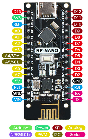
As a plan B I am trying to use one of these RF-NANO as the gateway, connecting a W5500 ethernet module. I still have to try this (I have just received the W5500 today) but I already have a question: The diagram and sketch for the W5100 ethernet gateway shows that the NRF24L01+ uses pins 5, 6, A0, A1 and A2, as the 'usual' pins 10, 11, 12 and 13 are used by the W5100. In the RF-NANO, the radio is already connected to pins 9 to 13.
Do you know how I can reallocate all pins in the sketch to match my setting?
-
@mioim Only the chip select pin needs to be different.
-
For plan A (Raspi gateway) I am still waiting for the new radio modules. I'm not scrapping this plan yet...
Regarding plan B (ethernet gateway), I am still confused regarding which pins to use and how to make it in the sketch:

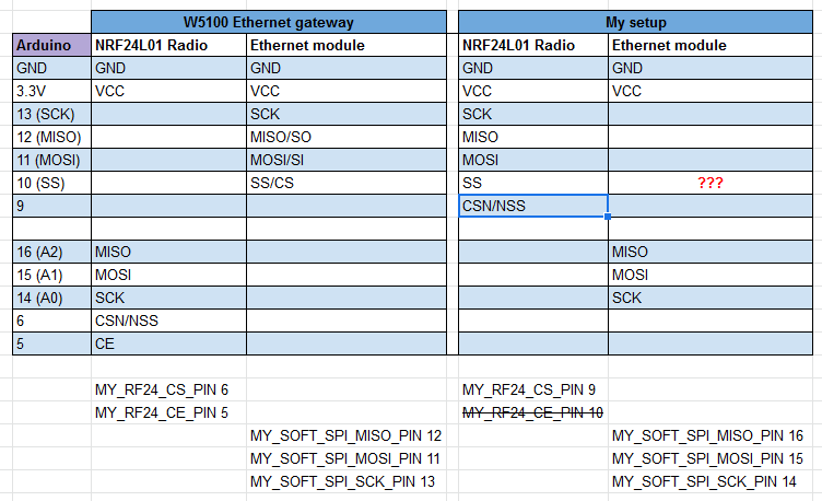
On the left are the pins used in the Ethernet Gateway page, with a nano, a W5100 and the NRF24L01+ radio. Also, the MY_RF24 and MY_SOFT_SPI commands in the original sketch.
On the right, the RF-NANO, W5500 and the NRF24L01+ radio I am trying to use. The pins of the radio are fixed, as both are in the same module:

Is the following correct?
-
(#1) the MY_RF24_CS_PIN is now pin 9 while MY_RF24_CE_PIN is the default one of the nano (pin 10, SS?) so it can be ommited (?).
-
(#2) the W5500 pins are the ones that have to be moved now. MISO, MOSI and SCK are going to pins 16, 15 and 14 with MY_SOFT_SPI (I am assuming the W5500 supports software SPI, I read yesterday that not all modules do)
-
(#3) where and how goes the SS pin of the W5500??? MY_SOFT_SPI_CE_PIN exists? Is this what you mean with your comment, @neverdie?
All this is really exciting, but I still have a lot to learn. Apologies again for the 'dumb' questions...
-