Ceech Board MOSFET Pin DIGITALWRITE Problem
-
Hi, I'm working with Ceech-Board for a pool sensor. I'm rewriting the code from V1.5 to 2.x. I encountered a problem with DIGITALWRITE which I can't explain.
Only if I set PINMODE unequal to the PIN for DIGITALWRITE, this output works.
void setup() {
  pinMode(5, OUTPUT); // Setzt den Digitalpin 13 als Outputpin
}

void loop() {
  digitalWrite(4, HIGH); // Setzt den Digitalpin 13 auf HIGH = "Ein"
  delay(1000);            // Wartet eine Sekunde
  digitalWrite(4, LOW);  // Setzt den Digitalpin 13 auf LOW = "Aus"
  delay(1000);            // Wartet eine Sekunde
}
It worked with pin 3, 5 and 13 e.g.
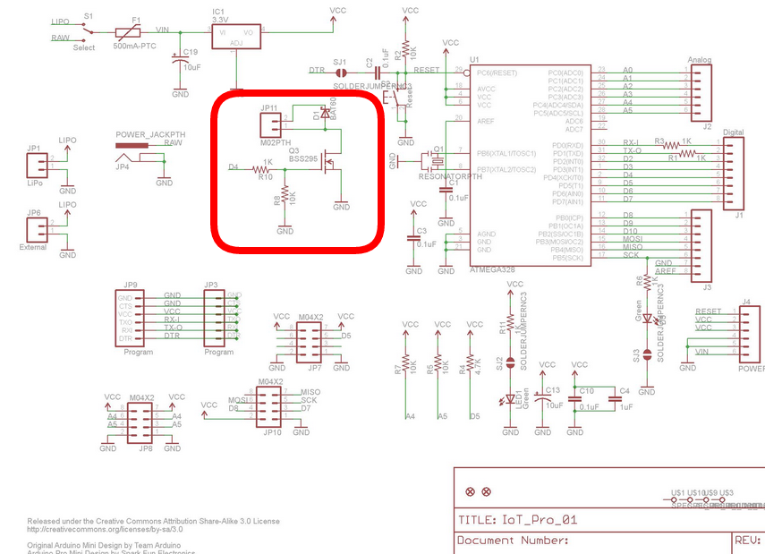
On the board the PIN D4 is followed by a MOSFET for switching. This worked once, once again not. No I seem to have found the problem, but what is the cause?
-
@paqor I recently converted the sketch to 2.x . Here it goes:
/**
 * The MySensors Arduino library handles the wireless radio link and protocol
 * between your home built sensors/actuators and HA controller of choice.
 * The sensors forms a self healing radio network with optional repeaters. Each
 * repeater and gateway builds a routing tables in EEPROM which keeps track of the
 * network topology allowing messages to be routed to nodes.
 *
 * Created by Henrik Ekblad <henrik.ekblad@mysensors.org>
 * Copyright (C) 2013-2015 Sensnology AB
 * Full contributor list: https://github.com/mysensors/Arduino/graphs/contributors
 *
 * Documentation: http://www.mysensors.org
 * Support Forum: http://forum.mysensors.org
 *
 * This program is free software; you can redistribute it and/or
 * modify it under the terms of the GNU General Public License
 * version 2 as published by the Free Software Foundation.
 *
 *******************************
 *
 * REVISION HISTORY
 * Version 1.0 - Initial Version by rvendrame
 *
 ******************************
 * DESCRIPTION
 * Floating Swiming pool sensor based on ceech's arista board
 *   (see https://www.tindie.com/products/ceech/astri-arista/ )
 *   Solar-powered (+Li-ion 18650 battery backup)
 * PH Measurement via A3 pin,  using DFrobot SEN0161 PH sensor
 *    (see https://www.dfrobot.com/wiki/index.php/PH_meter(SKU:_SEN0161)
 * ORP Measurement via A1 pin,  using Phidgets 1130_0 board + 3556_0 Electrode
 *    (see http://www.phidgets.com/products.php?product_id=1130)
 *    (see http://www.phidgets.com/products.php?product_id=3556)
 * Temp sensor via D4 pin,  using DS18B20 sensor
 *    (see https://create.arduino.cc/projecthub/TheGadgetBoy/ds18b20-digital-temperature-sensor-and-arduino-9cc806 )
 *
 *    Revisions:
 *    1.0  ( ??? 2017 ) - Initial version
 *    1.1  ( Jan 2020 ) - MySensors 2.x port
 */

// Enable debug prints to serial monitor
//#define MY_DEBUG

// CEECH BOARD
#define CEECH

// Define a static node address, AUTO or 1-255 fixed
#define MY_NODE_ID AUTO
#define MY_PARENT_NODE_ID AUTO

// Enable and select radio type attached
#define MY_RADIO_RF24  // MY_RADIO_RFM69

// MySensors
#define SN "myPoolWater"
#define SV "1.2"
#ifdef CEECH
#define MY_RF24_CE_PIN 7 // Ceech Arista board
#define MY_RF24_CS_PIN 8 // Ceech Arista board
#endif

// Includes -------------------------------------------
#include <MySensors.h>
#include <SPI.h>
#include <OneWire.h>
#include <DallasTemperature.h>

// External IO Pins
#define PH_PIN           A3  // pH Sensor dfrobot SKU SEN0161
#define ORP_PIN          A1  // ORP Sensor phidgets ASR2801 (3556_0) + 1103_0
#define ONE_WIRE_BUS     5   // One wire bus

// Runtime constants
#define day 86400000L // 86400000 milliseconds in a day
#define hour 3600000L // 3600000 milliseconds in an hour
#define minute 60000L // 60000 milliseconds in a minute
#define second  1000L // 1000 milliseconds in a second

// Ceech-Arista Internal connections
#define  current A6  // Charging current from Solar Panel
#define  cell    A2  // Voltage at Solar Panel
#define  lipo    A0  // Voltage at Battery
#define  CHRG    A7  // Charge indicator ( 0 means 'charging' )
#define  POWER   4   // MOSFET driver on 5V Step up (to power the sensors)
#define  R1      47000.0  // resistance of R1
#define  R2      10000.0  // resistance of R2

// mySensors objects
MyMessage ph_msg( 2, V_PH ),
          orp_msg( 3, V_ORP ),
          temp_msg( 1, V_TEMP ),
          bat_msg( 199 , V_VOLTAGE ),
          var1_msg( 0 , V_VAR1 ),
          var2_msg( 0 , V_VAR2 ),
          var3_msg( 0 , V_VAR3 );

// Setup a oneWire instance to communicate with any OneWire devices
// (not just Maxim/Dallas temperature ICs)
OneWire oneWire(ONE_WIRE_BUS);

// Pass our oneWire reference to Dallas Temperature.
DallasTemperature dallas(&oneWire);

// Misc
#define pHOffset         0.00  // pH deviation compensate
#define samplingInterval 20    // in miliseconds
#define arrayLenth       40    // times of collection

// PH / ORP / Temp  Reading
static unsigned long samplingTime = millis();
static float temp, ph, orp, voltage;
static float aux, dif, old_ph=999, old_orp=999, old_temp=999;
int   battery, counter = -1,
      old_bat=999, old_volt=9999;


int readings[arrayLenth];   //Store the average value of the sensor feedback
int arrayIndex = 0;

// Misc
float vout = 0.0;
float vin = 0.0;
int value = 0;

//// SETUP
void setup() {

  Serial.begin( MY_BAUD_RATE );
  Serial.println(F("Init..."));

  // IO PINS
  pinMode( POWER   , OUTPUT );
  pinMode( PH_PIN  , INPUT );
  pinMode( ORP_PIN , INPUT );

}

//// PRESENTATION
void presentation() {

  sendSketchInfo(SN, SV);

  present( 1, S_TEMP );          // Temperature
  present( 2, S_WATER_QUALITY ); // PH
  present( 3, S_WATER_QUALITY ); // ORP

}
//// LOOP
void loop() {

  // Force a refresh on each hour...
  if ( ++counter == 5 ) {
    old_ph = old_orp = old_temp = -999;
    old_bat = old_volt = -999;
    counter = 0;
  }

  // Internal board/battery status
  digitalWrite( POWER , true );
  Serial.println("5V Power ON - Wait 5s");
  wait(5000);

  float napetost = readVcc();

  Serial.println("*Internal:");

  value = analogRead(cell);
  vout = (value * napetost) / 1024.0;
  vin = vout / (R2 / (R1 + R2));
  if (vin < 0.09) vin = 0.0;

  float tok = ((analogRead(current) * napetost / 1024 ) * 250) / 3.3; // convert the ADC value to miliamps
  float baterija = ( analogRead(lipo) * napetost / 1024 ) * 2; // measuring battery voltage
  int polnjenje = analogRead(CHRG);

  Serial.print("Vcc = ");
  Serial.print(napetost);
  Serial.println("V");
  //delay(400);
  Serial.print("Charge current = ");
  Serial.print(tok);
  Serial.println("mA");
  //delay(400);
  Serial.print("Solar cell voltage = ");
  Serial.print(vin);
  Serial.println("V");
  //delay(400);
  Serial.print("Battery voltage = ");
  Serial.print(baterija);
  Serial.print("V  ");
  aux = constrain( map( baterija*1000 , 2200 , 4000 , 0 , 100 ) , 0 , 100 );
  Serial.print( aux , 0  );
  Serial.println("%");
  dif = aux - old_bat;
  if ( abs( dif ) > 0 ) {
    old_bat = aux;
    send( bat_msg.set(baterija,2) );
    sendBatteryLevel( aux) ;
    send ( var3_msg.set(vin,2) );
  }
  //delay(400);
  Serial.print("CHRG = ");
  Serial.println(polnjenje);

  Serial.println("*External:");

  //////// Temp Reading
  dallas.begin();  // Start up the library
  dallas.requestTemperatures();
  temp = dallas.getTempCByIndex(0);
  Serial.print( "Temperature: ");
  Serial.println( temp , 2 );
  dif = old_temp - temp;
  if ( abs( dif ) > 0.01 ) {
     old_temp = temp;
     send( temp_msg.set( temp , 2 ) ) ;
  }

  //////// PH Reading
  arrayIndex = 0;
  while ( arrayIndex < arrayLenth )
    if (millis() - samplingTime > samplingInterval)
    {
      readings[arrayIndex++] = analogRead(PH_PIN);
      samplingTime = millis();
    }

  voltage = avergearray( readings, arrayLenth ) * 3.30 / 1024.0;
  ph = 3.5 * ( voltage + pHOffset );

  Serial.print("PH Probe voltage:");
  Serial.print(voltage, 4);
  Serial.print("    pH value: ");
  Serial.println( ph , 2);
  dif = old_ph - ph;
  if ( abs( dif ) > 0.005 ) {
     old_ph = ph;
     send( ph_msg.set( ph , 2 ) ) ;
     send( var1_msg.set( voltage, 4) );
  }


  /////////// ORP
  arrayIndex = 0;
  while ( arrayIndex < arrayLenth )
    if (millis() - samplingTime > samplingInterval)
    {
      readings[arrayIndex++] = analogRead(ORP_PIN);
      samplingTime = millis();
    }

  voltage = avergearray( readings, arrayLenth ) * 3.31 / 1024.0;
  orp = ( 2.5 - voltage ) / 1.037 ;

  Serial.print("ORP Probe voltage:");
  Serial.print( voltage, 4);
  Serial.print("    ORP value: ");
  Serial.println( orp, 2 );
  dif = old_orp - orp;
  if ( abs( dif ) > 0.005 ) {
     old_orp = orp;
     send( orp_msg.set( orp , 2 ) ) ;
     send( var2_msg.set( voltage, 4) );
  }

  /////////// Sleep
  digitalWrite( POWER , false );
  Serial.println("5V Power OFF");

  Serial.print("Runtime: ");
  time();
  Serial.println("Pausing...");
  Serial.println("----------------------------");

  //delay(715000);
  wait(500);
  sleep( 715000U );   // Sleeps for 12m

}

double avergearray(int* arr, int number) {
  int i;
  int max, min;
  double avg;
  long amount = 0;
  if (number <= 0) {
    Serial.println("Error number for the array to avraging!/n");
    return 0;
  }
  if (number < 5) { //less than 5, calculated directly statistics
    for (i = 0; i < number; i++) {
      amount += arr[i];
    }
    avg = amount / number;
    return avg;
  } else {
    if (arr[0] < arr[1]) {
      min = arr[0]; max = arr[1];
    }
    else {
      min = arr[1]; max = arr[0];
    }
    for (i = 2; i < number; i++) {
      if (arr[i] < min) {
        amount += min;      //arr<min
        min = arr[i];
      } else {
        if (arr[i] > max) {
          amount += max;  //arr>max
          max = arr[i];
        } else {
          amount += arr[i]; //min<=arr<=max
        }
      }//if
    }//for
    avg = (double)amount / (number - 2);
  }//if
  return avg;
}


void time() {

  long timeNow = millis();

  int days = timeNow / day ;                                //number of days
  int hours = (timeNow % day) / hour;                       //the remainder from days division (in milliseconds) divided by hours, this gives the full hours
  int minutes = ((timeNow % day) % hour) / minute ;         //and so on...
  int seconds = (((timeNow % day) % hour) % minute) / second;

  // digital clock display of current time
  Serial.print(days, DEC);
  printDigits(hours);
  printDigits(minutes);
  printDigits(seconds);
  Serial.println();

}

void printDigits(byte digits) {
  // utility function for digital clock display: prints colon and leading 0
  Serial.print(":");
  if (digits < 10)
    Serial.print('0');
  Serial.print(digits, DEC);
}


/* Read internal Vcc reference
 *
 */
float readVcc()
{
  signed long resultVcc;
  float resultVccFloat;
  // Read 1.1V reference against AVcc
  ADMUX = _BV(REFS0) | _BV(MUX3) | _BV(MUX2) | _BV(MUX1);
  delay(10);                           // Wait for Vref to settle
  ADCSRA |= _BV(ADSC);                 // Convert
  while (bit_is_set(ADCSRA, ADSC));
  resultVcc = ADCL;
  resultVcc |= ADCH << 8;
  resultVcc = 1126400L / resultVcc;    // Back-calculate AVcc in mV
  resultVccFloat = (float) resultVcc / 1000.0; // Convert to Float

  return resultVccFloat;
}
-
Oh, thank you so much. I had to make some small changes though. Maybe it's the newer Ceech Board version.
 // IO PINS
  pinMode( 13  , OUTPUT ); //unclear why this is so

...


  present(0, S_MULTIMETER);
  present(0, S_CUSTOM);
...

digitalWrite( POWER , HIGH );

...

digitalWrite( POWER , LOW );
-
The MOSFET_outputs are two blank pins. I haven't found anything official about this, except in a post here and a circuit. I supply the voltage converter with VCC and at the bottom of these pins towards the RESET button.

-
@paqor said in Ceech Board MOSFET Pin DIGITALWRITE Problem:
You have to set pinMode for the same pin as you want to use as a output.. That is, if you use
pinMode(5, OUTPUT);you also need to usedigitalWrite(5, HIGH);See documentation hereIf you do not set pinMode for a particular pin, then that pin will be set as input by default. And then digitalWrite() will enable / disable the internal pullup on that particular pin.
I also suggest that you use a #define to make sensible names for your pins, that will make your code more readable:
#define RELAY_PIN 5

void setup() {
  pinMode(RELAY_PIN, OUTPUT); // Setzt den Digitalpin 13 als Outputpin
}

void loop() {
  digitalWrite(RELAY_PIN, HIGH); // Setzt den Digitalpin 13 auf HIGH = "Ein"
  delay(1000);            // Wartet eine Sekunde
  digitalWrite(RELAY_PIN, LOW);  // Setzt den Digitalpin 13 auf LOW = "Aus"
  delay(1000);            // Wartet eine Sekunde
}
-
Unfortunately, it's not that simple. Then it would have worked. What else could have caused this strange behavior?
-
This post is deleted!
-
This post is deleted!
-
hello, he runs, after much effort and nerves

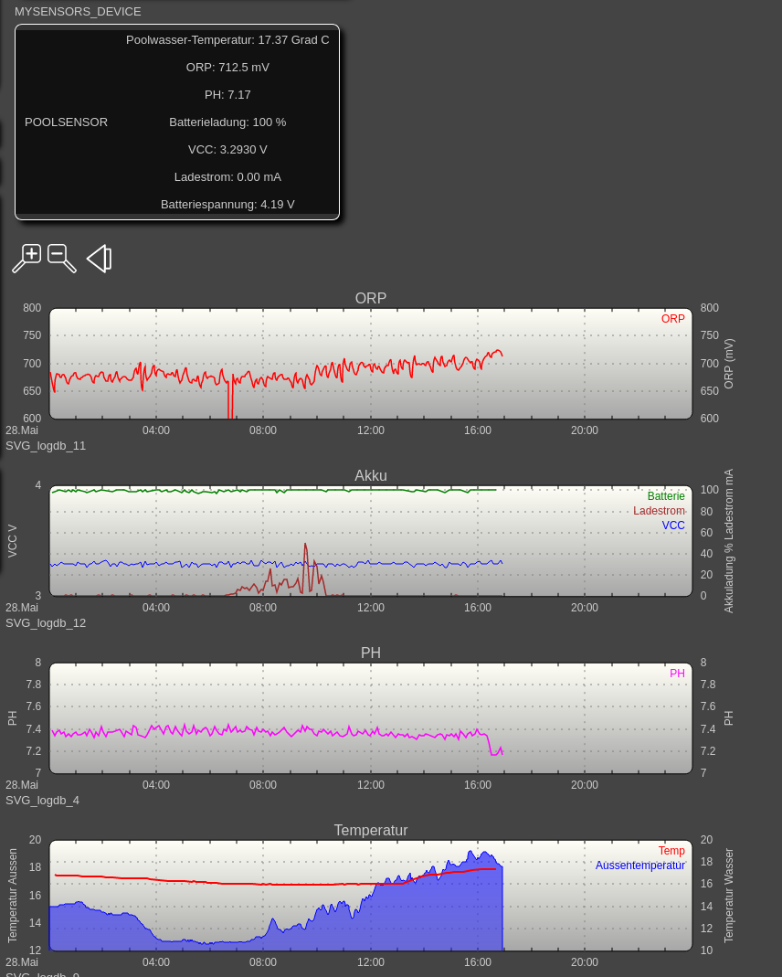
The values are a little bit very fluctuating? Probably you can only get away with a very accurate stable voltage of 5.0V.