433MHz amplified (>5V)
-
Hi!
For the remote wall plugs I currently have a 433 Mhz transceiver which sends proper code and turns them on and off.
When I've moved to new location I have problems with signal reaching the outlets as the distance went a little further (but nothing above 'normal flat' values).In specification of TX 433MHz (basic, cheap China one0 it's stated that it can be powered with voltage 5-12V. Now it's powered from Arduino but I'd like to connect 9V-12V power supply and feed the power staight to module.
Unfortunately specs also say that 'HIGH" voltage value of DATA pin should be at least 1/2 of Vcc, so for 12V it's 6V, which Arduino won't supply. I've tried to connect PN2222A to drive the power exactly to pin, but I couldn't get it to work (it worked for 1 of 5 tries to send code which reached outlet).
Any ideas/schematics how to connect and rive the module to get maximum output power while being properly sent by Arduino?
Unfortunately, itnernet seems to be quiet about the topic and I can see a lot of experienced PCB-designers, so maybe with a little help I can finally make something more reliable...Regards,
Andrew -
@andriej said:
Any ideas/schematics how to connect and rive the module to get maximum output power while being properly sent by Arduino?
have you thought about transistor switching?
-
I've thought and I've once even tried.
I don't know if I wired it properly, but it wasn't much more reliable than it was without transistor.I can't find schematics including transistor and resistors how to connect it properly and how to prevent arduino resetting while TX module was transmitting (I've encountered this problem).
-
@andriej said:
how to prevent arduino resetting while TX module was transmitting
separate the power supplies and test it, powering each one separately. Use the transistor to switch the radio's Vcc (with the base of the transistor connected to your arduino's output pin).
The signal from the arduino with this switching method can be shifted up to the voltage for the radio.
look for a small signal NPN transistor, and google "Transistor Switching"
-
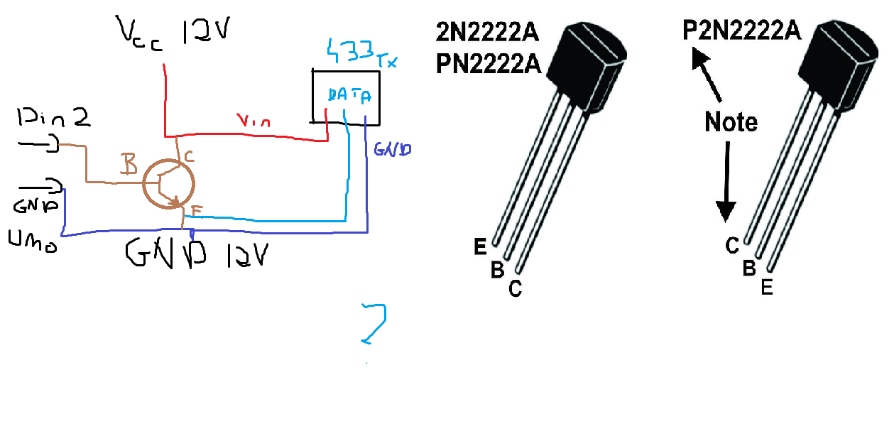
I got the PN2222A but I struggle what should be connected to emitter, base and collector. What my thougt was: emitter to Data pin, collector to Vcc of 12v supply and base to arduino data pin, no resistors used.
But should the gnd be both connected? And Vcc of 433 TX is connected to +12v power supply.
It is Uno so I can power it with usb separately. -
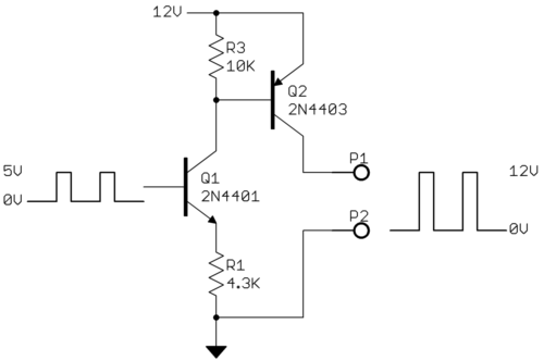
@andriej That's not the right way as there's nothing (other than the transistor) limiting the current between Vcc and GND. What you need to do is level shift the output of Pin 2 (0 to 5V) to the data input of the 433 module. The best way to level shift would be to do something like this:

See http://electronics.stackexchange.com/questions/17581/best-way-to-get-5v-or-12v-or-0v-from-arduino-pin for details on this circuit.
Cheers
Al -
@andriej That's not the right way as there's nothing (other than the transistor) limiting the current between Vcc and GND. What you need to do is level shift the output of Pin 2 (0 to 5V) to the data input of the 433 module. The best way to level shift would be to do something like this:

See http://electronics.stackexchange.com/questions/17581/best-way-to-get-5v-or-12v-or-0v-from-arduino-pin for details on this circuit.
Cheers
Al -
@Sparkman thank you for your reply!
So I'd need two transistors - that's ok... But how (and which one) do I connect to DATA pin (as I assume)?
Or i could bridge P1 and P2 mentioned on schematics above? -
@andriej It'll do the job of Q1, but Q2 is a PNP transistor. For it you would need something like the 2N2907, 2N3906 or 2N4403.
-
@Sparkman time for getting parts as I don't have PNP in house.
Thank you. :-) Tommorow I'll test it out.Just to be 100% sure - both GND's should be connected together (Uno's and 12V supply?)
-
@andriej said:
Just to be 100% sure - both GND's should be connected together (Uno's and 12V supply?)
Yes, that's correct.
Cheers
Al@Sparkman thank you very much, it worked absolutely flawless. I can now again control the switches, will test it with different voltages and antennas.
One more thing - I've read some time ago that it might be worth considering a capacitor (polarized one) at least 10uF conected to transmitter's Vcc and GND.
Do you think it could stabilize power and smooth it even more, so the quality of signal and strenght could be even better?As a antenna currently I use the core from coax tv cable, 174mm long - straight without any shielding.
Regards
-
@Sparkman thank you very much, it worked absolutely flawless. I can now again control the switches, will test it with different voltages and antennas.
One more thing - I've read some time ago that it might be worth considering a capacitor (polarized one) at least 10uF conected to transmitter's Vcc and GND.
Do you think it could stabilize power and smooth it even more, so the quality of signal and strenght could be even better?As a antenna currently I use the core from coax tv cable, 174mm long - straight without any shielding.
Regards
-
@andriej Glad to hear it's working. A capacitor between Vcc an GND can help smooth any ripple. It won't hurt to add it if you have one kicking around.
Cheers
Al@Sparkman strange thing happened and suddenly everything stopped working.
After rewiring (still leaving everything the same, just restarting of power supply) it worked for few minutes and stopped.
Currently I've moved from ethernet shield to plain Uno (so only 2 pins are used: GND and D2 - TX Data) and still can't get signal out of the module...
I even rewrote the code leaving everything not needed outside. Now I will be removing the cap between Vcc and GND.
Hope it helps.. -
The only idea I have is that it stopped working because voltage went 12,4V…
But all components (except TX module?) should accept it.
I've switched from LAN to serial now and back to normal 5V with special antenna. -
@Sparkman it will be hard for me to test now, as I've soldered everything on breadboard.
What other PNP transistor would you fit instead of 2N4403?
I will be buying few of them and can't exactly find the 440x's@andriej Digikey has a good transistor selector. You can see the specs for the 4403 and then find something with similar specs that may be more readily available where you live.
Cheers
Al

