
Mailbox/Postbox Alert
-
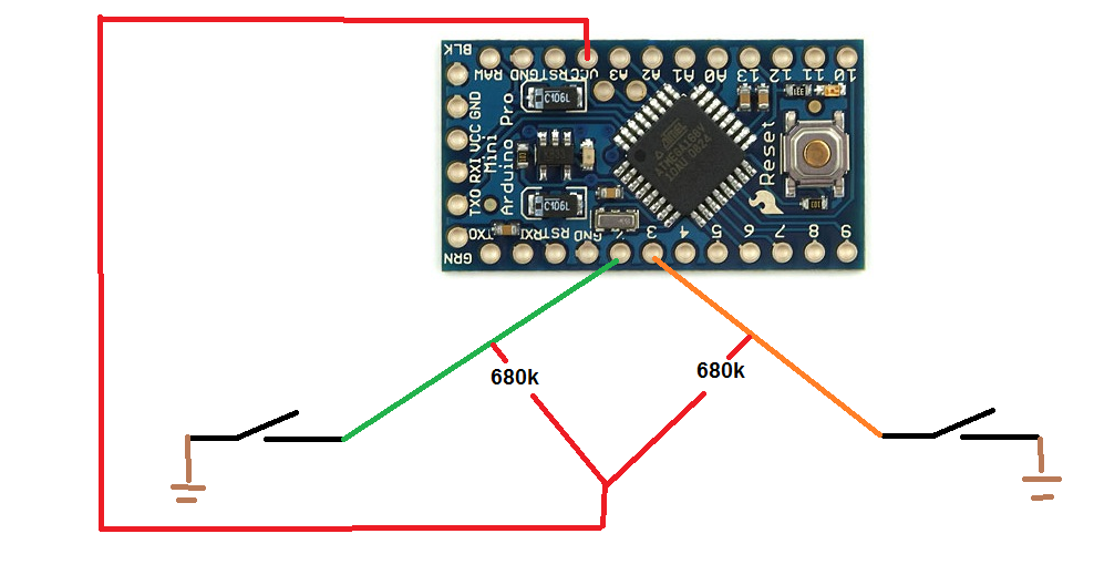
@Moshe-Livne just deactivate the this lines:
//digitalWrite(MAILBOX_FRONT_PIN, HIGH);
//digitalWrite(MAILBOX_BACK_PIN, HIGH);and solder two resistor from 3.3v to pin 2 and 3.
-
Ok, so I found that it is the radio that draws about 7mA when I ground input pin 2, it is connected to IRQ-pin on the radio.
@n3ro Have you connected the radio as described on the build-page? [http://www.mysensors.org/build/connect_radio](link url) -
I'm guessing that your repeat() function is wearing out the battery.
By the way you can take advantage of the return of sleep( ) here:
gw.sleep(MAILBOX_FRONT_PIN - 2, CHANGE, MAILBOX_BACK_PIN - 2, CHANGE, 0);like this (untested):
#include <MySensor.h> #include <SPI.h> #include <readVcc.h> #define NODE_ID 21 // ID of node #define CHILD_ID 1 // Id of the sensor child #define MAILBOX_FRONT_PIN 2 // Arduino Digital I/O pin for button/reed switch #define MAILBOX_BACK_PIN 3 // Arduino Digital I/O pin for button/reed switch #define MIN_V 1900 // empty voltage (0%) #define MAX_V 3200 // full voltage (100%) MySensor gw; MyMessage msg(CHILD_ID, V_TRIPPED); boolean post = false; boolean lastpost = false; int oldBatteryPcnt; int repeat = 20; int trigger = -1; unsigned long goToSleepTime; void setup() { gw.begin(NULL, NODE_ID, false); pinMode(MAILBOX_FRONT_PIN, INPUT); pinMode(MAILBOX_BACK_PIN, INPUT); digitalWrite(MAILBOX_FRONT_PIN, HIGH); digitalWrite(MAILBOX_BACK_PIN, HIGH); gw.sendSketchInfo("Mailbox Alert", "1.0"); gw.present(CHILD_ID, S_MOTION); Serial.println("---------- set Mailbox empty"); msg.set(0); } void loop() { if (millis() - goToSleepTime > 10UL) //debounce { switch (trigger) { case 0: post = true; Serial.println("---------- New Mail"); break; case 1: post = false; Serial.println("---------- Mailbox emptied"); break; default: Serial.println("---------- I just woke up"); } } trigger = -1; if (post != lastpost) { Serial.print("---------- Send Mailboxstate "); Serial.println(post ? "full" : "empty"); msg.set(post); lastpost = post; sendBattery(); } // Sleep until something happens with the sensor goToSleepTime = millis(); trigger = gw.sleep(MAILBOX_FRONT_PIN - 2, CHANGE, MAILBOX_BACK_PIN - 2, CHANGE, 0); } void sendBattery() // Measure battery { int batteryPcnt = min(map(readVcc(), MIN_V, MAX_V, 0, 100), 100); if (batteryPcnt != oldBatteryPcnt) { gw.sendBatteryLevel(batteryPcnt); // Send battery percentage oldBatteryPcnt = batteryPcnt; } Serial.print("---------- Battery: "); Serial.println(batteryPcnt); }@BulldogLowell could you please explain your changes? I don't understand everything of this :sweat:
-
@n3ro Ok, thanks! Then I learned something new today.. IRQ is only needed for receiving nodes then, like repeaters and gateways, right?
Strange though that my circuit draws so much more current than yours. I have tested different setups, different arduinos and different radios from different suppliers with same result.
Well, at least my mailbox are mysensored now! :smiley: -
-
-
Nope, havent done that yet. It´s a "stock" 3v3 pro mini. Still reading up on how to do that and how to change to MYS-bootloader, curious on how OTA-update works.
Big thanks for your respons! :smile:@f1dev sweebe wrote a very good howto:
http://forum.pimatic.org/topic/383/tips-battery-powered-sensors
pimatic + MySensors + Homeduino + z-way
https://github.com/n3roGit/MySensors_n3ro -
-
@f1dev sweebe wrote a very good howto:
http://forum.pimatic.org/topic/383/tips-battery-powered-sensors
@n3ro Brilliant! He recommends to take out the voltage regulator. it is easier (and works better) just to snip off one leg as described here http://www.mysensors.org/build/battery. I'll try his other mods.... hopefully now my nodes will last forever!!!!
-
quality project, been having a tinker with mixed results. used sketch from original post, but would it be possible to get a circuit diagram showing pull up locations??? bit of a beginner, but have had a few success with rolling out some power operated sensors , this is my first battery operated sensor...
-
-
quality project, been having a tinker with mixed results. used sketch from original post, but would it be possible to get a circuit diagram showing pull up locations??? bit of a beginner, but have had a few success with rolling out some power operated sensors , this is my first battery operated sensor...
-
thanks for the diagram, much appreciated...
-
Hello,
Does this code still work?
Thank you




Hello! It looks like you're interested in this conversation, but you don't have an account yet.
Getting fed up of having to scroll through the same posts each visit? When you register for an account, you'll always come back to exactly where you were before, and choose to be notified of new replies (either via email, or push notification). You'll also be able to save bookmarks and upvote posts to show your appreciation to other community members.
With your input, this post could be even better 💗
Register Login