Solar powered LED motion activated light with MySensors upgrade
-
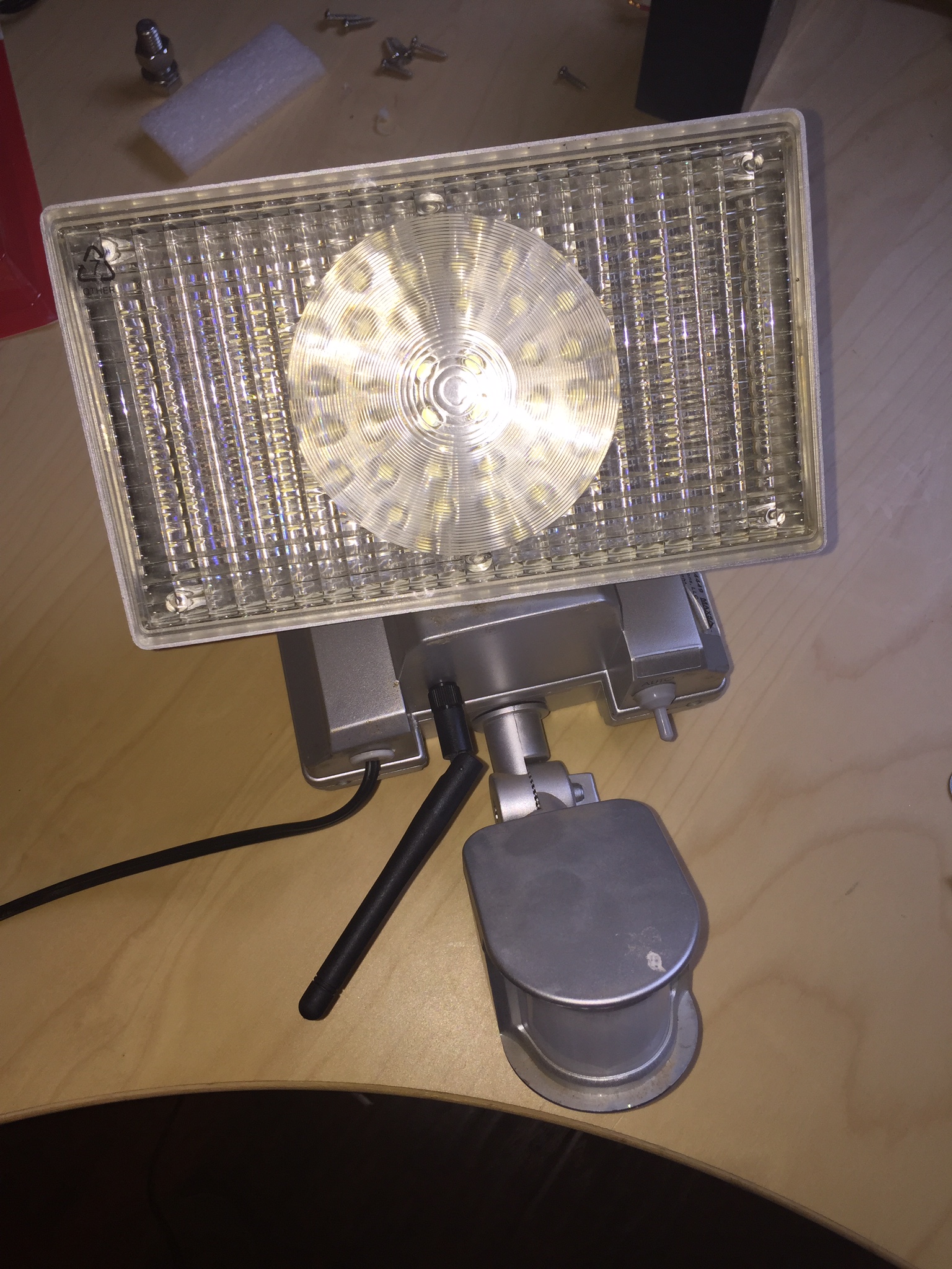
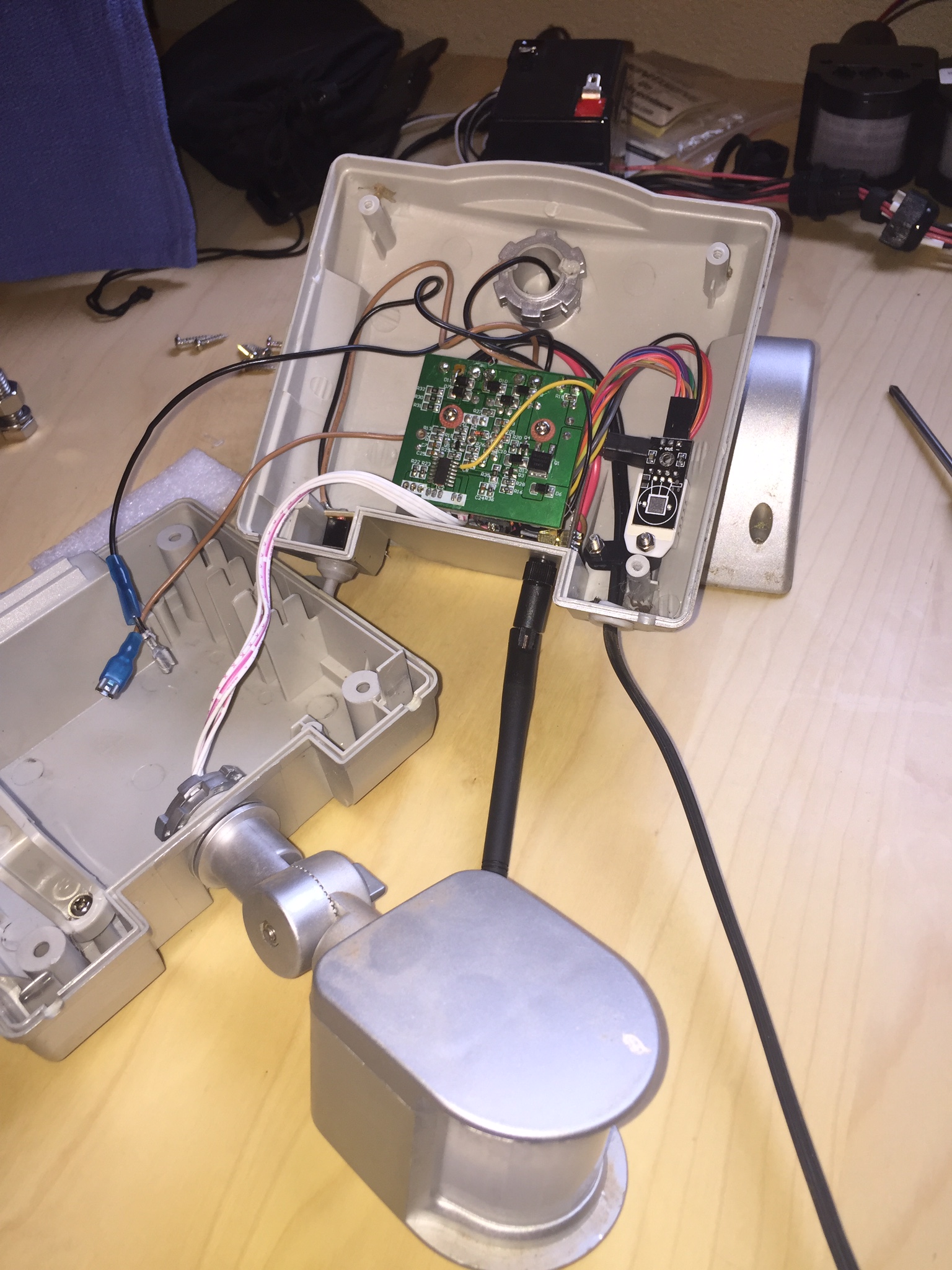
I would like to share a recent project I did where I modified my Motion activated MAXSA 44449-L Silver 100-LED Solar-Powered Security Floodlight to include a nice MySensor upgrade! I used the 3.3v pro-mini and the NRF24L01+PA+LNA antenna version because of the 300m distance from the gateway. To my surprise it all fit perfectly well inside the existing chassis without modification besides the hole I had to drill for the antenna! It's been working great and running for about 3 weeks now without a glitch and graphing all sensors on Domoticz.
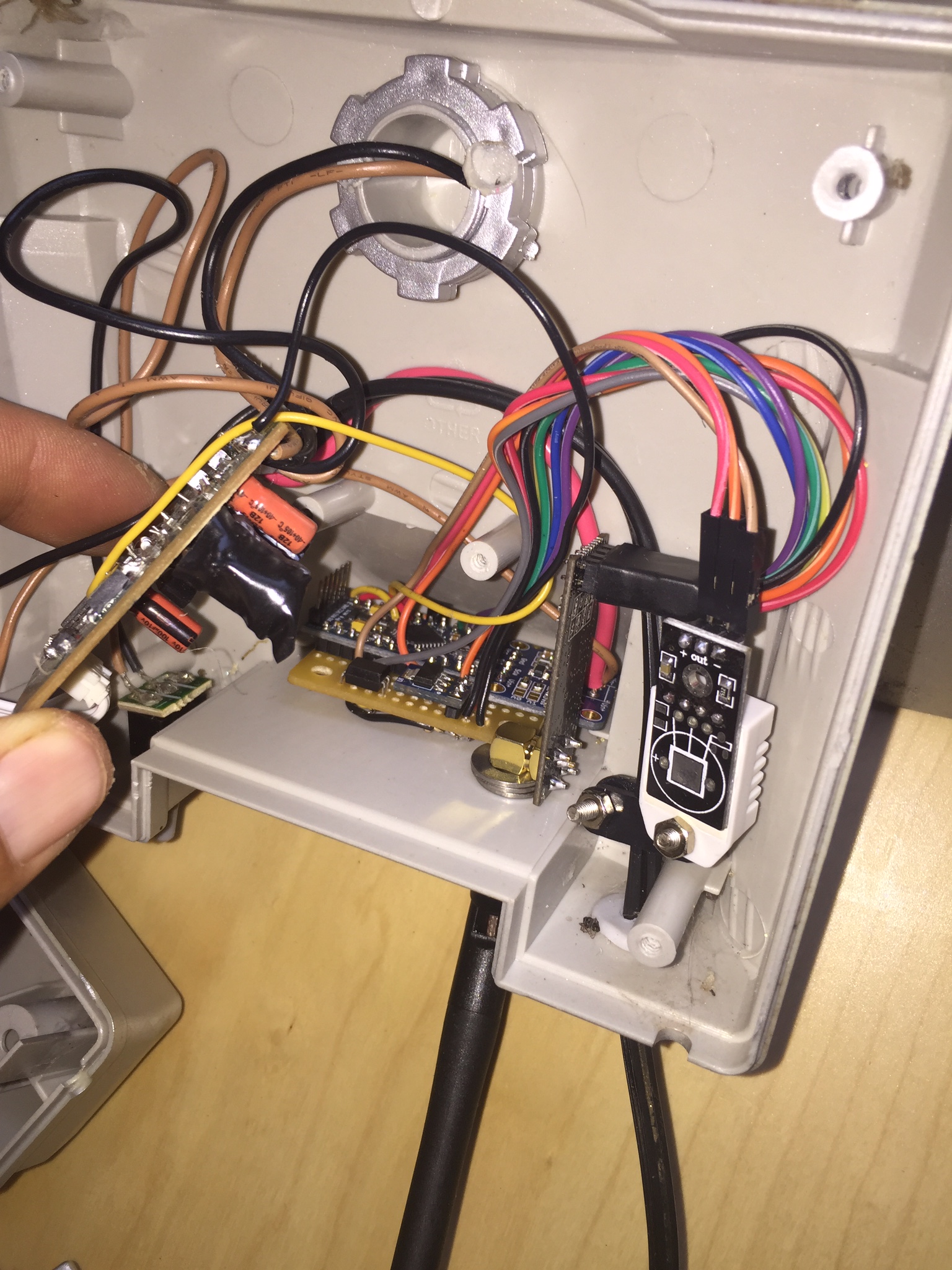
During the build and testing phase I ran into problem when sensing the motion output as the motion trigger output voltage only runs at 2.6 volts causing a very erratic detection with the pro mini digital input. So I had to build a simple transistor and optoisolator circuit to step up the output trigger voltage to 3.3 volts.
Features I included:
-sends back motion trigger status (most important!)
-sends temp and humidity using DHT22 probe(why not?)
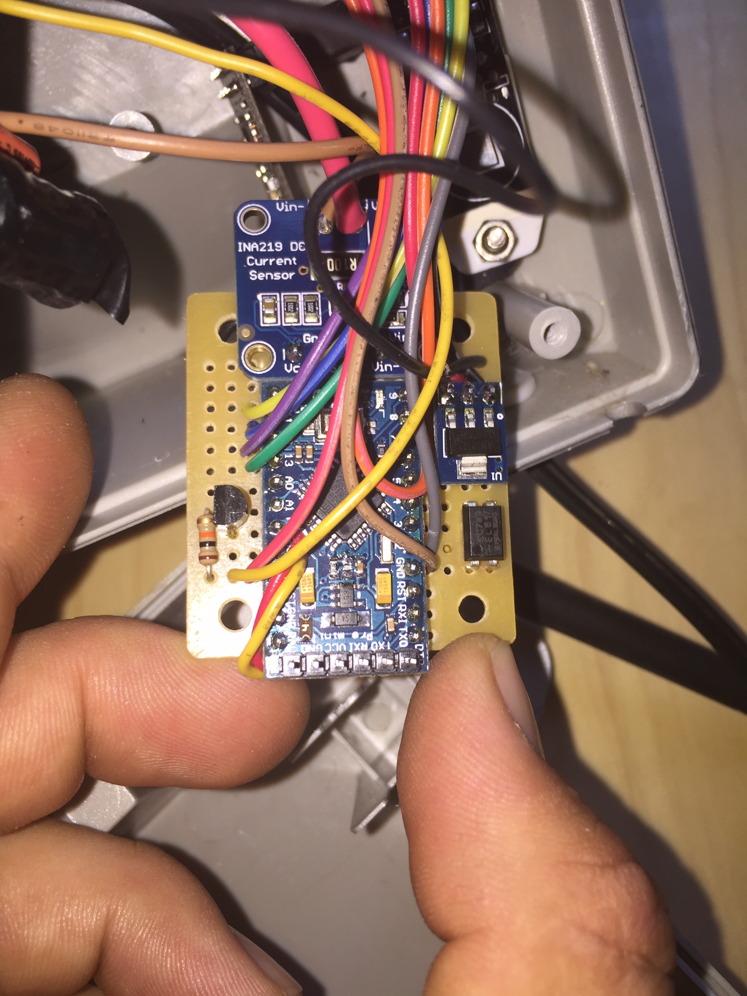
-sends battery and watt usage including what comes in from the included solar panel during the day using the adafruit ina219 breakout board!
-
I would like to share a recent project I did where I modified my Motion activated MAXSA 44449-L Silver 100-LED Solar-Powered Security Floodlight to include a nice MySensor upgrade! I used the 3.3v pro-mini and the NRF24L01+PA+LNA antenna version because of the 300m distance from the gateway. To my surprise it all fit perfectly well inside the existing chassis without modification besides the hole I had to drill for the antenna! It's been working great and running for about 3 weeks now without a glitch and graphing all sensors on Domoticz.
During the build and testing phase I ran into problem when sensing the motion output as the motion trigger output voltage only runs at 2.6 volts causing a very erratic detection with the pro mini digital input. So I had to build a simple transistor and optoisolator circuit to step up the output trigger voltage to 3.3 volts.
Features I included:
-sends back motion trigger status (most important!)
-sends temp and humidity using DHT22 probe(why not?)
-sends battery and watt usage including what comes in from the included solar panel during the day using the adafruit ina219 breakout board!
@HighSierraJoe What chip and pin did you tap into on the original PIR board? I tried this with a BISS0001 chip on a motion night light and tapped into the OUT2 pin (2nd opamp output) but could not get a steady signal. I would be curious to know how you tapped into and used that signal.
-
@Dwalt I could not find the model of the chip as there is nothing printed on top of it, so I had to use my fluke and check each pin until I found the output signal. You can see in the bottom picture I soldered the yellow wire onto pin 13. Then as I mentioned earlier the signal voltage output was only 2.6 volts, right around the threshold for digital input detection, so when motion was triggered my readings were erratic. To fix this I had to build a simple transistor and optoisolator circuit to up convert the signal to 3.3 volts and satisfy the pro mini when detecting the motion trigger signal.
@HighSierraJoe What transistor did you use? I couldn't see from the photos how you wired this up. I have a 4N25 optocoupler laying around so I want to try this with my nightlight. I was trying to pull from pin12 which is the output from the second opamp of the IC (I am sure they are the same ICs or equivalents) but my voltage fluttered around 1.5 and dropped to 0 on motion but wouldn't trigger interrupts due to being on the edge of the 'logic zone', essentially the same problem you had.
One interesting thing I noticed from watching the voltage directly from the IC was on movement in front of the PIR from the left to right would trigger a small spike before dropping to 0 and movement from right to left would cause a quick dip, recover and then drop to 0. If that short dip or spike could be captured and interpreted, a PIR could be used to tell what direction motion was coming from.
-
@HighSierraJoe Two thumbs up!! I am going to find my flood light and see how much room there is.
-
@Dwalt I used a general purpose BC547B transistor. The voltage drop was too low to use this alone so thats why I added a pc817 optoisolator as well! Im not very savvy with these kinds of circuits, but what I did is wire the signal source to a 10k resistor then to base. Vcc to 270ohm resistor into optoisolator then out to collector. Emitter to common ground. Don't forget the 10k pull down on the optoisolator output! In your case the wiring will be slightly different since your triggered signal is the inverse of mine!