My Slim 2AA Battery Node
-
A couple of more questions. In one of the pictures at the top the electrulyte 4,.7 uf capacitator is placed closer to the atmel chip and the 0.1 uf (c5) is placed closest to the edge does it matter witch capacitator goes where?
The 10k resistor should be 1/4 or 1/8 W according to the bom. I had some small 1/6 W 10k resistors can I use them? I also have some bigger blue 10k resistor that I do not know the W rating on.
Where did you purchase the female pin-header that are used for the chips? I have some atmega chip-sockets that are quite narrow and it is hard to fit the components underneath. I also have some other female pin-headers but they are atleast twice as high than the ones in the pictures.
@Cliff-Karlsson You can swap the capacitors and use all resistor dissipation values. The pin headers you can find here for example
-
@Yveaux I tried to find an email address on the website, but apart from a LinkIn link I could not find anything. Also, in LinkedIn you need a paying version to be able to send InMail, and I do not have a paid account. Would you care to tell me how you were able to send Stijn a message ?
@GertSanders It's been a while, but my first contact was through his Twitter account. Try that first, otherwise ping me.
-
@GertSanders It's been a while, but my first contact was through his Twitter account. Try that first, otherwise ping me.
@Yveaux I do not have a twitter account, so no joy. And I feel stupid to say so, but how do you ping someone on this forum ?
-
@AWI said:
panelized design
If you're struggling with panelizing boards I can recommend the excellent gerber tools from Stijn Kuipers.
It allows you to create designs like this (10x10cm, DirtyPCBs):
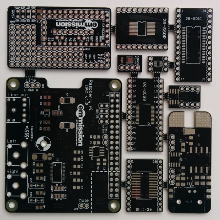
Drop him a message and he'll send you a download link.
@Yveaux i remember once that i read that dirtypcbs does not allow for different designs in their panelized boards. Am i correct ?
-
@Yveaux i remember once that i read that dirtypcbs does not allow for different designs in their panelized boards. Am i correct ?
-
@ahmedadelhosni apparently not :blush:
The board above was produced by ditypcb's. In fact they're one of the few (only?) cheap PCB manufacturers that allow panelization.@Yveaux aha. I thought that this means multiple (same) design not different. Thanks :)
-
Updated first post with share stats and info.
Feature requests and example links will come asap.
-
This post is deleted!
-
Hi
I've just ordered a set of the PCB boards and looking forward to putting these together mainly into reed switches and motion sensors
I have scanned the whole thread and there doesn't seem to be a comprehensive list of exactly which components are required anywhere here, well not all in one place at least.
Can I just confirm exactly what is required to build a senor node.
1 x PDB board
1 x ATMega328p 28pin PDIP
1 x NRF24L01+ radio module
1 x 4.7uF Decoupling-Capacitor for radio (I assume these are still required??)
1 x right angle pin header for connecting to program and connect batteries
1 x Length of cable ducting for housing
2 x AA batteries
Cables for connecting batteries
Battery connector
1 x senor of choice
I notice there seem to be an assortment of capacitors/regulators in most of the photos on this thread, but no definitive list of which are needed. (I am very new to all this so please excuse my ignorance)Extras needed
1 x FTDI USB to TTL Serial AdapterHave I missed anything of my list? Also I would be really grateful for links to some of the above components.
Sorry these are very basic noob questions, but I feel it would really helpful for people such as myself to have everything clearly listed in one place, as the main mysensors build pages do. So people know exactly what is needed.
-
@Matt-Pitts You can find a BOM for the board here:
https://www.openhardware.io/view/10/My-Slim-2AA-Battery-Node
-
A nice additions would be a place to solder a ATSHA204A on board like the Sensebender! I'll try to make the change in KiCad!
-
A nice additions would be a place to solder a ATSHA204A on board like the Sensebender! I'll try to make the change in KiCad!
-
Thanks @GertSanders for showing me the BOM I hadn't realised it was there, but do I need everything listed there to get it working properly?
-
Thanks @GertSanders for showing me the BOM I hadn't realised it was there, but do I need everything listed there to get it working properly?
@Matt-Pitts
I'm assuming that if a designer goes through the trouble of listing items on a bom, they are needed.But you are right, that is not always the case. I'm not at my Mac (using a miniscreen now), so i can not multitask.
-
Hello,
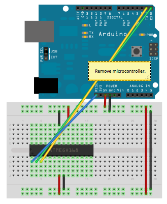
I have problems to upload the scatch to the bare Amtel. I use an USB-TTL FTL Adaper and connect, RX/TX and Reset Pin with 100n->DTR. But I got always errors on uploading.The bootloader I have successfull burned with an raspberry pi and gpio (http://www.lxccu.com/hb-raspberry-bootloader-update):
sudo bin/avrdude -Cbin/avrdude.conf -p m328p -P gpio -c gpio -U lfuse:w:0x62:m -U hfuse:w:0xde:m -U efuse:w:0x07:m -U lock:w:0x2F:m -e -Uflash:w:1443392692398-atmega328_1a.hex:i
avrdude: safemode: Fuses OKHow can I got it working?
Thank youThomas
-
@bjacobse No, used the bootloader from here (http://forum.mysensors.org/uploads/files/1443392692398-atmega328_1a.hex). This is an bootloader for the internal clock.
Baud settings to upload the sketch or the bootloader? -
@m26872 Sure, but not with an bootloader (optiboot with intenal clock) on an bare Atmega. Later I will try this: http://forum.mysensors.org/uploads/files/1454449901412-7.png
I build some MySensors with an Arduino Micro, but not with only an Atmega.Update: I don't know what's different, but this works. Perhaps I forget to connect Reset from FDL -> Pin 1.
Now I can upload simple sketches.
Hello! It looks like you're interested in this conversation, but you don't have an account yet.
Getting fed up of having to scroll through the same posts each visit? When you register for an account, you'll always come back to exactly where you were before, and choose to be notified of new replies (either via email, or push notification). You'll also be able to save bookmarks and upvote posts to show your appreciation to other community members.
With your input, this post could be even better 💗
Register Login