My Slim 2AA Battery Node
-
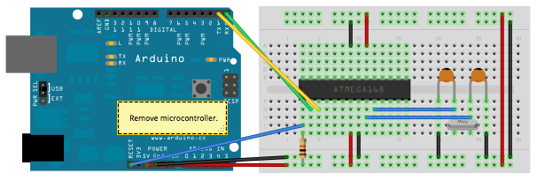
I just installed the NRF module at it´s desired place as well as the two capacitors and the resistors as described above. The crystal is only used for uploading the sketch to the Atmega328 chip, described here: https://www.arduino.cc/en/Tutorial/ArduinoToBreadboard
So a wiring issue should not be the problem. Also, the code should have been uploaded well, because when I put the chip back to the breadboard and fire up my Arduino I at least receive the "radio init fail" message.
I just wonder if you guys upload your sketches the same way or if you use a different setup. I know there is a way to upload the sketch without the 16MHz crystal and I would like to know if this could be the problem.
edit: I´ve re-read your first post and also this thread http://forum.mysensors.org/topic/3018/tutorial-how-to-burn-1mhz-8mhz-bootloader-using-arduino-ide-1-6-5-r5/2 ...
Do I have to burn the bootloader using 1MHz or 8 MHz? I don´t get why this makes a difference, only that the batteries would drain faster the higher the MHz rate is.
I already uploaded a bootloader on my chips with a 16MHz crystal. Could I just re-upload a new bottloader using 1 or 8 MHz and overwrite the 16MHz bootloader?
-
I just installed the NRF module at it´s desired place as well as the two capacitors and the resistors as described above. The crystal is only used for uploading the sketch to the Atmega328 chip, described here: https://www.arduino.cc/en/Tutorial/ArduinoToBreadboard
So a wiring issue should not be the problem. Also, the code should have been uploaded well, because when I put the chip back to the breadboard and fire up my Arduino I at least receive the "radio init fail" message.
I just wonder if you guys upload your sketches the same way or if you use a different setup. I know there is a way to upload the sketch without the 16MHz crystal and I would like to know if this could be the problem.
edit: I´ve re-read your first post and also this thread http://forum.mysensors.org/topic/3018/tutorial-how-to-burn-1mhz-8mhz-bootloader-using-arduino-ide-1-6-5-r5/2 ...
Do I have to burn the bootloader using 1MHz or 8 MHz? I don´t get why this makes a difference, only that the batteries would drain faster the higher the MHz rate is.
I already uploaded a bootloader on my chips with a 16MHz crystal. Could I just re-upload a new bottloader using 1 or 8 MHz and overwrite the 16MHz bootloader?
@siod The lowered MHz is not to drain battery slower. To save power we want to run wihtout buck- or boost (step-up or step-down) voltage regulators. When we do that, we need to ensure all circuit components work in whole battery voltage range. A good trade-off/design is then to make the Atmega work down to the same lower limit as the nRF24L01+, which is ~1.9V. Unfortunately the Atmega is unstable at high frequencies with low voltages. That why we need a low frequency. An external 4MHz should be low enough, but an easier, cheaper and usually good enough solution is to by the ATmega "fuse settings" activate an 8MHz internal crystal together with a "divide by 8" prescaler.
To fascilitate the use of noob-friendly Arduino IDE and concept of loading sketches and debug through a serial interface, we need to have a "bootloader" on the Atmega. The procedure you're referring to is how you put this bootloader to the ATmega. I would strongly recommend a beginner to start with ready made Arduinos in projects before starting to play with blank/bare ATmegas.
Whether you need the 16MHz crystal, 8MHz or none depends it's current fuse settings. Bootloader and fuse settings determine how you load, debug and run your sketch.
I think the guides, project threads, links and references provided here in the forum should be enough when you've come to the point where you can make it all the way. -
Did anybody tested this board with an ATSHA204A on A2? The ATSHA204A works with 2.0 to 5.5 V.
-
ok guys, I finally set up my first sensor and it´s communicating well. I´ve attached two reed switch which work fine, only my temp snesor DHT11 doesn´t work. Are there any known issues with this sensor?
pls have a look at my setup and my code, thank you:
// Simple binary switch example // Connect button or door/window reed switch between // digitial I/O pin 3 (BUTTON1_PIN below) and GND. #include <MySensor.h> #include <SPI.h> // Define Node ID #define MY_NODE_ID 1 //Kontaktschalter #include <Bounce2.h> #define CHILD1_ID 1 // Kontaktschalter 1 #define CHILD2_ID 2 // Kontaktschalter 1 #define BUTTON1_PIN 5 // Kontaktschalter 1 #define BUTTON2_PIN 6 // Kontaktschalter 2 //Tempsensor #include <DHT.h> #define CHILD_ID_HUM 3 #define CHILD_ID_TEMP 4 #define HUMIDITY_SENSOR_DIGITAL_PIN 4 unsigned long SLEEP_TIME = 30000; // Sleep time between reads (in milliseconds) MySensor gw; //Kontaktschalter Bounce debouncer1 = Bounce(); Bounce debouncer2 = Bounce(); int oldValueReed1=-1; int oldValueReed2=-1; //tempsensor DHT dht; float lastTemp; float lastHum; boolean metric = true; //Messages // Kontaktschalter MyMessage msgReed1(CHILD1_ID,V_TRIPPED); // Kontaktschalter 1 MyMessage msgReed2(CHILD2_ID,V_TRIPPED); // Kontaktschalter 2 //TempMessage MyMessage msgHum(CHILD_ID_HUM, V_HUM); MyMessage msgTemp(CHILD_ID_TEMP, V_TEMP); void setup() { gw.begin(NULL, MY_NODE_ID, true); //Tempsensor dht.setup(HUMIDITY_SENSOR_DIGITAL_PIN); // Setup Kontaktschalter 1 pinMode(BUTTON1_PIN,INPUT); // Activate internal pull-up digitalWrite(BUTTON1_PIN,HIGH); // Setup Kontaktschalter 2 pinMode(BUTTON2_PIN,INPUT); // Activate internal pull-up digitalWrite(BUTTON2_PIN,HIGH); // After setting up the button, setup debouncer debouncer1.attach(BUTTON1_PIN); debouncer2.attach(BUTTON2_PIN); debouncer1.interval(5); debouncer2.interval(5); // Register binary input sensor to gw (they will be created as child devices) // You can use S_DOOR, S_MOTION or S_LIGHT here depending on your usage. // If S_LIGHT is used, remember to update variable type you send in. See "msg" above. gw.present(CHILD1_ID, S_DOOR); gw.present(CHILD2_ID, S_DOOR); //Tempsensor gw.present(CHILD_ID_HUM, S_HUM); gw.present(CHILD_ID_TEMP, S_TEMP); metric = gw.getConfig().isMetric; } // Check if digital input has changed and send in new value void loop() { //Kontakstschalter 1 debouncer1.update(); // Get the update value int valueReed1 = debouncer1.read(); if (valueReed1 != oldValueReed1) { // Send in the new value gw.send(msgReed1.set(valueReed1==HIGH ? 1 : 0)); Serial.println("Button 1 geschaltet"); oldValueReed1 = valueReed1; } //Kontakstschalter 2 debouncer2.update(); // Get the update value int valueReed2 = debouncer2.read(); if (valueReed2 != oldValueReed2) { // Send in the new value gw.send(msgReed2.set(valueReed2==HIGH ? 1 : 0)); Serial.println("Button 2 geschaltet"); oldValueReed2 = valueReed2; } //Tempsensor delay(dht.getMinimumSamplingPeriod()); float temperature = dht.getTemperature(); if (isnan(temperature)) { Serial.println("Failed reading temperature from DHT"); } else if (temperature != lastTemp) { lastTemp = temperature; if (!metric) { temperature = dht.toFahrenheit(temperature); } gw.send(msgTemp.set(temperature, 1)); Serial.print("T: "); Serial.println(temperature); } float humidity = dht.getHumidity(); if (isnan(humidity)) { Serial.println("Failed reading humidity from DHT"); } else if (humidity != lastHum) { lastHum = humidity; gw.send(msgHum.set(humidity, 1)); Serial.print("H: "); Serial.println(humidity); } //gw.sleep(SLEEP_TIME); //sleep a bit }still learning...
-
ok guys, I finally set up my first sensor and it´s communicating well. I´ve attached two reed switch which work fine, only my temp snesor DHT11 doesn´t work. Are there any known issues with this sensor?
pls have a look at my setup and my code, thank you:
// Simple binary switch example // Connect button or door/window reed switch between // digitial I/O pin 3 (BUTTON1_PIN below) and GND. #include <MySensor.h> #include <SPI.h> // Define Node ID #define MY_NODE_ID 1 //Kontaktschalter #include <Bounce2.h> #define CHILD1_ID 1 // Kontaktschalter 1 #define CHILD2_ID 2 // Kontaktschalter 1 #define BUTTON1_PIN 5 // Kontaktschalter 1 #define BUTTON2_PIN 6 // Kontaktschalter 2 //Tempsensor #include <DHT.h> #define CHILD_ID_HUM 3 #define CHILD_ID_TEMP 4 #define HUMIDITY_SENSOR_DIGITAL_PIN 4 unsigned long SLEEP_TIME = 30000; // Sleep time between reads (in milliseconds) MySensor gw; //Kontaktschalter Bounce debouncer1 = Bounce(); Bounce debouncer2 = Bounce(); int oldValueReed1=-1; int oldValueReed2=-1; //tempsensor DHT dht; float lastTemp; float lastHum; boolean metric = true; //Messages // Kontaktschalter MyMessage msgReed1(CHILD1_ID,V_TRIPPED); // Kontaktschalter 1 MyMessage msgReed2(CHILD2_ID,V_TRIPPED); // Kontaktschalter 2 //TempMessage MyMessage msgHum(CHILD_ID_HUM, V_HUM); MyMessage msgTemp(CHILD_ID_TEMP, V_TEMP); void setup() { gw.begin(NULL, MY_NODE_ID, true); //Tempsensor dht.setup(HUMIDITY_SENSOR_DIGITAL_PIN); // Setup Kontaktschalter 1 pinMode(BUTTON1_PIN,INPUT); // Activate internal pull-up digitalWrite(BUTTON1_PIN,HIGH); // Setup Kontaktschalter 2 pinMode(BUTTON2_PIN,INPUT); // Activate internal pull-up digitalWrite(BUTTON2_PIN,HIGH); // After setting up the button, setup debouncer debouncer1.attach(BUTTON1_PIN); debouncer2.attach(BUTTON2_PIN); debouncer1.interval(5); debouncer2.interval(5); // Register binary input sensor to gw (they will be created as child devices) // You can use S_DOOR, S_MOTION or S_LIGHT here depending on your usage. // If S_LIGHT is used, remember to update variable type you send in. See "msg" above. gw.present(CHILD1_ID, S_DOOR); gw.present(CHILD2_ID, S_DOOR); //Tempsensor gw.present(CHILD_ID_HUM, S_HUM); gw.present(CHILD_ID_TEMP, S_TEMP); metric = gw.getConfig().isMetric; } // Check if digital input has changed and send in new value void loop() { //Kontakstschalter 1 debouncer1.update(); // Get the update value int valueReed1 = debouncer1.read(); if (valueReed1 != oldValueReed1) { // Send in the new value gw.send(msgReed1.set(valueReed1==HIGH ? 1 : 0)); Serial.println("Button 1 geschaltet"); oldValueReed1 = valueReed1; } //Kontakstschalter 2 debouncer2.update(); // Get the update value int valueReed2 = debouncer2.read(); if (valueReed2 != oldValueReed2) { // Send in the new value gw.send(msgReed2.set(valueReed2==HIGH ? 1 : 0)); Serial.println("Button 2 geschaltet"); oldValueReed2 = valueReed2; } //Tempsensor delay(dht.getMinimumSamplingPeriod()); float temperature = dht.getTemperature(); if (isnan(temperature)) { Serial.println("Failed reading temperature from DHT"); } else if (temperature != lastTemp) { lastTemp = temperature; if (!metric) { temperature = dht.toFahrenheit(temperature); } gw.send(msgTemp.set(temperature, 1)); Serial.print("T: "); Serial.println(temperature); } float humidity = dht.getHumidity(); if (isnan(humidity)) { Serial.println("Failed reading humidity from DHT"); } else if (humidity != lastHum) { lastHum = humidity; gw.send(msgHum.set(humidity, 1)); Serial.print("H: "); Serial.println(humidity); } //gw.sleep(SLEEP_TIME); //sleep a bit } -
Oh man, one problem solved, next just comes up...
So what can I Do now? Just upload the 8MHz bootloader and just use 8MHz instead of 1MHz?
edit: Ok, tested it, it works with the 8MHz Bootloader!
please explain one more time if I could just use the 8MHz Bootloader, I still could not fully understand why I should use the 1 MHz Bootloader (maybe because of my bad english and also my lack of electronics knowledge). Thank you very much!!
edit2: I measured 0,02 Ampere consumption, isn´t that too much?
-
OK thx for the hint, I guess I will just add a third AA battery, that should solve my problem...
-
I really don't want to spam this thread...
But from my arduino Uno the nrf24l01 module is also powered by 5V!?!
Edit : ah ok, the arduino is going to regulate down to 3.3v... Then I cant use 3AAs :(
-
I wasn't aware that the nrf24l01 is so sensitive to voltage higher than 1.9v. I would like to have a sensor design to which I can add different sensors, just for the purpose I need it right now. So most sensors need 3.3v or 5v and I have to decide if I use 3v cells, which are more expensive or use step up / step down regulators which will drain my batteries. I just want to keep the flexibility to add any sort of sensor to my board... What would you suppose to do, also I think I am not the only one who faces those problems. Of course I am a beginner and still have a lot to learn but I also just want to finish this project as I am working on it for a very long time now...
@siod said:
I wasn't aware that the nrf24l01 is so sensitive to voltage higher than 1.9v.
Typo? I suppose you mean 3.3V.
I would like to have a sensor design to which I can add different sensors...
Please reply why you don't like those two designs I linked to in my last post above.
-
5V as a supply voltage had been the standard for many decades.
As integrated circuits have become more compact and more efficient, 3.3V and 1.8V as supply voltages have become standards as well. 3.3V for most components, 1.8V is more recent and only used in some very highly integrated circuits.
For sensornodes based on batteries, the 3.3V standard is very usefull and most sensors are available for this working voltage.
If you really need 5V for a particular sensor, then think about AC or USB powered nodes. 5V sensors are a bad choice for battery based nodes. The 5V sensors are mostly old designs, and very inefficient when looking at them from a powerconsumption point of view.
So you can want to combine 3.3V and 5V sensors, but our experience is NOT to combine and make a choice for low power (modern) 3.3V sensors when trying to build battery based sensor nodes.
-
OK guys, thanks for the explanation. In this case I need to buy new temp sensors...
The 3.7v batteries are no option for me because they are too expensive in my eyes. I didn't want to buy new temp sensors as I already bought a couple of the DHT 11 sensors but it seems like there is no other chance now.
I just think the next time I encounter problems is, when I try to setup a new sensor node with attached pir motion sensor... I will read the data sheet of it first and look out for power consumption :)
-
Is there any motion sensor that work on 3.3 V ? I tried powering the below one with 3.3 but it was acting crazy and keeps reporting motions.
http://store.fut-electronics.com/products/pir-motion-sensor-module-adjustable-range
It is written that V range is 3-5 but it worked well with 5v only.
-
Is there any motion sensor that work on 3.3 V ? I tried powering the below one with 3.3 but it was acting crazy and keeps reporting motions.
http://store.fut-electronics.com/products/pir-motion-sensor-module-adjustable-range
It is written that V range is 3-5 but it worked well with 5v only.
@ahmedadelhosni Haven't you seen the motion example sensors in the first post of this thread?
Hello! It looks like you're interested in this conversation, but you don't have an account yet.
Getting fed up of having to scroll through the same posts each visit? When you register for an account, you'll always come back to exactly where you were before, and choose to be notified of new replies (either via email, or push notification). You'll also be able to save bookmarks and upvote posts to show your appreciation to other community members.
With your input, this post could be even better 💗
Register Login