Skip to content
  • MySensors
  • OpenHardware.io
  • Categories
  • Recent
  • Tags
  • Popular
Skins
  • Light
  • Brite
  • Cerulean
  • Cosmo
  • Flatly
  • Journal
  • Litera
  • Lumen
  • Lux
  • Materia
  • Minty
  • Morph
  • Pulse
  • Sandstone
  • Simplex
  • Sketchy
  • Spacelab
  • United
  • Yeti
  • Zephyr
  • Dark
  • Cyborg
  • Darkly
  • Quartz
  • Slate
  • Solar
  • Superhero
  • Vapor

  • Default (No Skin)
  • No Skin
Collapse
Brand Logo
  1. Home
  2. OpenHardware.io
  3. 💬 Easy/Newbie PCB for MySensors

💬 Easy/Newbie PCB for MySensors

Scheduled Pinned Locked Moved OpenHardware.io
mysensorsbatteryeasynewbiepcbmysx
716 Posts 111 Posters 305.9k Views 93 Watching
  • Oldest to Newest
  • Newest to Oldest
  • Most Votes
Reply
  • Reply as topic
Log in to reply
This topic has been deleted. Only users with topic management privileges can see it.
  • sundberg84S Offline
    sundberg84S Offline
    sundberg84
    Hardware Contributor
    wrote on last edited by sundberg84
    #115

    @lxz This is my code (Note dev branch!) for DHT22 incl battery measuring (2xAA).
    The reason for readVCC:h does not work is that you measure after the booster = always 3.3V!

    // Enable debug prints
    #define MY_DEBUG
    
    // Enable and select radio type attached
    #define MY_RADIO_NRF24
    //#define MY_RADIO_RFM69
    #define MY_NODE_ID 15
    
    #include <SPI.h>
    #include <MySensor.h>  
    #include <DHT.h>  
    
    #define CHILD_ID_HUM 0
    #define CHILD_ID_TEMP 1
    #define HUMIDITY_SENSOR_DIGITAL_PIN 3
    unsigned long SLEEP_TIME = 600000; // Sleep time between reads (in milliseconds)
    
    #define SKETCH_NAME "UtomhusHumSyd #15"                // Change to a fancy name you like
    #define SKETCH_VERSION "1.0"                    // Your version
    
    DHT dht;
    float lastTemp;
    float lastHum;
    boolean metric = true; 
    MyMessage msgHum(CHILD_ID_HUM, V_HUM);
    MyMessage msgTemp(CHILD_ID_TEMP, V_TEMP);
    
    //=========================
    // BATTERY VOLTAGE DIVIDER SETUP
    // 1M, 470K divider across battery and using internal ADC ref of 1.1V
    // Sense point is bypassed with 0.1 uF cap to reduce noise at that point
    // ((1e6+470e3)/470e3)*1.1 = Vmax = 3.44 Volts
    // 3.44/1023 = Volts per bit = 0.003363075
    #define VBAT_PER_BITS 0.003363075  
    #define VMIN 1.9                                  //  Vmin (radio Min Volt)=1.9V (564v)
    #define VMAX 3.0                                  //  Vmax = (2xAA bat)=3.0V (892v)
    int batteryPcnt = 0;                              // Calc value for battery %
    int batLoop = 0;                                  // Loop to help calc average
    int batArray[3];                                  // Array to store value for average calc.
    int BATTERY_SENSE_PIN = A0;                       // select the input pin for the battery sense point
    //=========================
    
    void setup()  
    { 
     analogReference(INTERNAL);             // For battery sensing
    
      delay(500); // Allow time for radio if power used as reset
      
      dht.setup(HUMIDITY_SENSOR_DIGITAL_PIN); 
    
      metric = getConfig().isMetric;
    }
    
    void presentation()  
    { 
      // Send the Sketch Version Information to the Gateway
     // Send the Sketch Version Information to the Gateway
      sendSketchInfo(SKETCH_NAME, SKETCH_VERSION);
    
      // Register all sensors to gw (they will be created as child devices)
      present(CHILD_ID_HUM, S_HUM);
      present(CHILD_ID_TEMP, S_TEMP);
    }
    
    void loop()      
    {  
      delay(500); // Allow time for radio if power used as reset
      delay(dht.getMinimumSamplingPeriod());
     
      // Fetch temperatures from DHT sensor
      float temperature = dht.getTemperature();
      if (isnan(temperature)) {
          Serial.println("Failed reading temperature from DHT");
      } else if (temperature != lastTemp) {
        lastTemp = temperature;
        if (!metric) {
          temperature = dht.toFahrenheit(temperature);
        }
        send(msgTemp.set(temperature, 1));
        Serial.print("T: ");
        Serial.println(temperature);
      }
      
      // Fetch humidity from DHT sensor
      float humidity = dht.getHumidity();
      if (isnan(humidity)) {
          Serial.println("Failed reading humidity from DHT");
      } else if (humidity != lastHum) {
          lastHum = humidity;
          send(msgHum.set(humidity, 1));
          Serial.print("H: ");
          Serial.println(humidity);
      }
      batM();
      sleep(SLEEP_TIME); //sleep a bit
    }
    
    void batM() //The battery calculations
    {
       delay(500);
       // Battery monitoring reading
       int sensorValue = analogRead(BATTERY_SENSE_PIN);    
       delay(500);
       
       // Calculate the battery in %
       float Vbat  = sensorValue * VBAT_PER_BITS;
       int batteryPcnt = static_cast<int>(((Vbat-VMIN)/(VMAX-VMIN))*100.);
       Serial.print("Battery percent: "); Serial.print(batteryPcnt); Serial.println(" %");  
       
       // Add it to array so we get an average of 3 (3x20min)
       batArray[batLoop] = batteryPcnt;
      
       if (batLoop > 2) {  
         batteryPcnt = (batArray[0] + batArray[1] + batArray[2] + batArray[3]);
         batteryPcnt = batteryPcnt / 3;
     
       if (batteryPcnt > 100) {
         batteryPcnt=100;
     }
     
         Serial.print("Battery Average (Send): "); Serial.print(batteryPcnt); Serial.println(" %");
           sendBatteryLevel(batteryPcnt);
           batLoop = 0;
          }
         else 
         {
         batLoop++;
         }
    }```

    Controller: Proxmox VM - Home Assistant
    MySensors GW: Arduino Uno - W5100 Ethernet, Gw Shield Nrf24l01+ 2,4Ghz
    MySensors GW: Arduino Uno - Gw Shield RFM69, 433mhz
    RFLink GW - Arduino Mega + RFLink Shield, 433mhz

    1 Reply Last reply
    0
    • pkriekP Offline
      pkriekP Offline
      pkriek
      wrote on last edited by
      #116

      Hi

      I also bought v8 of these boards. 2 sensors up an running perfect.

      2 others modules on the other hand, I think I fried the arduino. I am using 5v mini's. They worked when programming thru the USB port. Also communication with domoticz. They stopped working when I attached the 6v external adapter. I connected these to the ground and power connector. Now lights go on, but nothing anymore also not on the serial monitor.

      Should I have used the raw connector????

      thanks for helping

      1 Reply Last reply
      0
      • sundberg84S Offline
        sundberg84S Offline
        sundberg84
        Hardware Contributor
        wrote on last edited by sundberg84
        #117

        Short answer - yes you should have used RAW. But at least you learned a lesson if you want to think positive. ☺

        Try and see what happens if you change. Maybe they are still OK.

        Controller: Proxmox VM - Home Assistant
        MySensors GW: Arduino Uno - W5100 Ethernet, Gw Shield Nrf24l01+ 2,4Ghz
        MySensors GW: Arduino Uno - Gw Shield RFM69, 433mhz
        RFLink GW - Arduino Mega + RFLink Shield, 433mhz

        1 Reply Last reply
        1
        • pkriekP Offline
          pkriekP Offline
          pkriek
          wrote on last edited by
          #118

          thanks!, lessons learned indeed. . Great stuff though.

          1 Reply Last reply
          1
          • scooter217S Offline
            scooter217S Offline
            scooter217
            wrote on last edited by
            #119

            what size terminal blocks do you buy? I bought some and they are the wrong size.

            S 1 Reply Last reply
            0
            • scooter217S scooter217

              what size terminal blocks do you buy? I bought some and they are the wrong size.

              S Offline
              S Offline
              Samuel235
              Hardware Contributor
              wrote on last edited by Samuel235
              #120

              @scooter217, from a quick inspection of the .brd file and a look around the internet for the datasheets it would seem that sundberg has allowed for any screw terminal block that uses a 5mm pin pitch. So you would need a 3 terminal 5mm pin pitch screw terminal. Please allow @sundberg84 some time to reply to ensure I am correct.

              MySensors 2.1.1
              Controller - OpenHAB (Virtual Machine)
              Gateway - Arduino Mega MQTT Gateway W5100

              1 Reply Last reply
              1
              • sundberg84S Offline
                sundberg84S Offline
                sundberg84
                Hardware Contributor
                wrote on last edited by
                #121

                @scooter217 : http://www.ebay.com/sch/sis.html?_nkw=20pcs+KF301-2P+2+Pin+Plug-in+Screw+Terminal+Block+Connector+5.08mm+Pitch&_id=181759858196&&_trksid=p2057872.m2749.l2658

                Controller: Proxmox VM - Home Assistant
                MySensors GW: Arduino Uno - W5100 Ethernet, Gw Shield Nrf24l01+ 2,4Ghz
                MySensors GW: Arduino Uno - Gw Shield RFM69, 433mhz
                RFLink GW - Arduino Mega + RFLink Shield, 433mhz

                scooter217S 1 Reply Last reply
                0
                • sundberg84S sundberg84

                  @scooter217 : http://www.ebay.com/sch/sis.html?_nkw=20pcs+KF301-2P+2+Pin+Plug-in+Screw+Terminal+Block+Connector+5.08mm+Pitch&_id=181759858196&&_trksid=p2057872.m2749.l2658

                  scooter217S Offline
                  scooter217S Offline
                  scooter217
                  wrote on last edited by
                  #122

                  @sundberg84 Thank you, just ordered some from ebay!

                  1 Reply Last reply
                  1
                  • M Offline
                    M Offline
                    Matt
                    wrote on last edited by Matt
                    #123

                    Hi Sundberg.
                    First of all thanks for what you have done here, and hi from New Zealand.
                    I have a problem though, sorry to be a hassle.
                    I assembled my first board tonight and I dont get 3.3v across the NRF. It starts at 0.07V then falls down to 0 on my cheap meter. Same on the MYSX1.4 connector at 3.3 and gnd. Am getting 3.3 on the mini as well as VCC and GND on the MYSX area so the regulator is working. May be a short? Or a bad solder? Although they look good to me.... If so what solder joints should I redo? Any other ideas?
                    Also, Ive traced back the VCC from the NRF and I cant see where it connects to a power source, either the battery in or the boost converter?
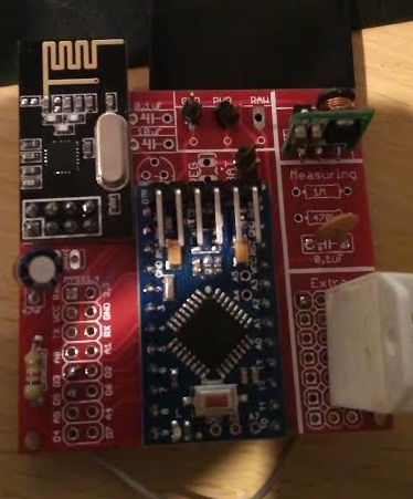
                    0_1461234488858_MS.jpg

                    Thanks,
                    Matt

                    sundberg84S 1 Reply Last reply
                    0
                    • M Matt

                      Hi Sundberg.
                      First of all thanks for what you have done here, and hi from New Zealand.
                      I have a problem though, sorry to be a hassle.
                      I assembled my first board tonight and I dont get 3.3v across the NRF. It starts at 0.07V then falls down to 0 on my cheap meter. Same on the MYSX1.4 connector at 3.3 and gnd. Am getting 3.3 on the mini as well as VCC and GND on the MYSX area so the regulator is working. May be a short? Or a bad solder? Although they look good to me.... If so what solder joints should I redo? Any other ideas?
                      Also, Ive traced back the VCC from the NRF and I cant see where it connects to a power source, either the battery in or the boost converter?
                      0_1461234488858_MS.jpg

                      Thanks,
                      Matt

                      sundberg84S Offline
                      sundberg84S Offline
                      sundberg84
                      Hardware Contributor
                      wrote on last edited by
                      #124

                      @Matt Hi Matt - tnx.

                      Try to measure here: whats your reading?
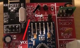
                      0_1461234892945_1.jpg
                      if its 3.3v its your radio thats has some error... this is prettu much the last point before radio. Also measure VCC/GND under the pcb and not on top, what does it say?

                      Sounds like a short or bad solder...

                      Controller: Proxmox VM - Home Assistant
                      MySensors GW: Arduino Uno - W5100 Ethernet, Gw Shield Nrf24l01+ 2,4Ghz
                      MySensors GW: Arduino Uno - Gw Shield RFM69, 433mhz
                      RFLink GW - Arduino Mega + RFLink Shield, 433mhz

                      M 1 Reply Last reply
                      0
                      • sundberg84S sundberg84

                        @Matt Hi Matt - tnx.

                        Try to measure here: whats your reading?
                        0_1461234892945_1.jpg
                        if its 3.3v its your radio thats has some error... this is prettu much the last point before radio. Also measure VCC/GND under the pcb and not on top, what does it say?

                        Sounds like a short or bad solder...

                        M Offline
                        M Offline
                        Matt
                        wrote on last edited by
                        #125

                        @sundberg84
                        Ah crikey I think Im being thick, I just put a jumper across BAT connectors after tracing the lines and reading the manual, am now getting 2.8 at the NRF. Sorry for being a numpty. Still not picking up on my gateway, time to go to bed but will get the serial monitor running tomorrow....
                        Thanks for the quick reply.

                        1 Reply Last reply
                        0
                        • ValleV Offline
                          ValleV Offline
                          Valle
                          wrote on last edited by
                          #126

                          Finally got my boards. In color: Yellow.
                          If I would skip the Booster is the esiest thing to just wire Vi - Vo?

                          0_1462250321694_IMG_4703.JPG

                          1 Reply Last reply
                          0
                          • N Offline
                            N Offline
                            nunver
                            wrote on last edited by
                            #127

                            I have a question about using this board as a gateway. Pinout of Mini Pro and Nano are almost identical. I built an adapter board to plug in a Nano into this board. Pin by pin control shows it is OK. I checked connectivity with MYSController. The gateway boots up. When I turn on my battery powered sensor, it asks for ID, the gateway "supposedly" sends it. I watch this from the messages. The sensor does not register. It asks four more times, the gateway responds four times. But sensor could not be ID'd and of course registered.

                            I am thinking either reception problem on sensor side, or transmission problem on gateway side? Could it be a power problem related with design of the board? Is there any way to identify?

                            Thanks

                            1 Reply Last reply
                            0
                            • sundberg84S Offline
                              sundberg84S Offline
                              sundberg84
                              Hardware Contributor
                              wrote on last edited by
                              #128

                              @Valle - yes you can just put a wire between left and right pin - but it wont work for a long time (the pro mini will die when battery goes below 3v i think).

                              @nunver - I have never used this board as gateway. What does your controller say, does it apply an ID for the request?

                              Controller: Proxmox VM - Home Assistant
                              MySensors GW: Arduino Uno - W5100 Ethernet, Gw Shield Nrf24l01+ 2,4Ghz
                              MySensors GW: Arduino Uno - Gw Shield RFM69, 433mhz
                              RFLink GW - Arduino Mega + RFLink Shield, 433mhz

                              ValleV N 2 Replies Last reply
                              0
                              • sundberg84S sundberg84

                                @Valle - yes you can just put a wire between left and right pin - but it wont work for a long time (the pro mini will die when battery goes below 3v i think).

                                @nunver - I have never used this board as gateway. What does your controller say, does it apply an ID for the request?

                                ValleV Offline
                                ValleV Offline
                                Valle
                                wrote on last edited by
                                #129

                                @sundberg84

                                I'm using mfalkvidds Plant monitoring
                                mfalkvidd said:

                                An update on battery life: The sensor in my bonsai tree has been reporting every 11,5 minutes since 2015-11-07, so over the last ~four months it has done 24,504 measurements. The battery level has gone from 3.187V to 3.142V, which means a drop of 0.01125V per month. Assuming I let it go down to 2.34V (limit for 8MHz according to the datasheet) and that the voltage drop is linear, I should get (3.187-2.34)/0.01125 = 75 months = ~6 years. There are several error sources in this calculation, but it looks like battery life will be quite good, even though the sensor reports much more often than necessary.

                                So I will try without Booster. But for other sensors I will use booster.

                                sundberg84S 1 Reply Last reply
                                1
                                • ValleV Valle

                                  @sundberg84

                                  I'm using mfalkvidds Plant monitoring
                                  mfalkvidd said:

                                  An update on battery life: The sensor in my bonsai tree has been reporting every 11,5 minutes since 2015-11-07, so over the last ~four months it has done 24,504 measurements. The battery level has gone from 3.187V to 3.142V, which means a drop of 0.01125V per month. Assuming I let it go down to 2.34V (limit for 8MHz according to the datasheet) and that the voltage drop is linear, I should get (3.187-2.34)/0.01125 = 75 months = ~6 years. There are several error sources in this calculation, but it looks like battery life will be quite good, even though the sensor reports much more often than necessary.

                                  So I will try without Booster. But for other sensors I will use booster.

                                  sundberg84S Offline
                                  sundberg84S Offline
                                  sundberg84
                                  Hardware Contributor
                                  wrote on last edited by
                                  #130

                                  @Valle said:

                                  So I will try without Booster. But for other sensors I will use booster.

                                  Sounds good - let us know how it works out for you. 2,34V is for a genuine Arduino so you know - I dont think a clone manages that... also the last energy (from 1,9 to 2,34v) is not used even though the radio could handle it if you used a booster.

                                  Controller: Proxmox VM - Home Assistant
                                  MySensors GW: Arduino Uno - W5100 Ethernet, Gw Shield Nrf24l01+ 2,4Ghz
                                  MySensors GW: Arduino Uno - Gw Shield RFM69, 433mhz
                                  RFLink GW - Arduino Mega + RFLink Shield, 433mhz

                                  1 Reply Last reply
                                  0
                                  • Boots33B Offline
                                    Boots33B Offline
                                    Boots33
                                    Hero Member
                                    wrote on last edited by
                                    #131

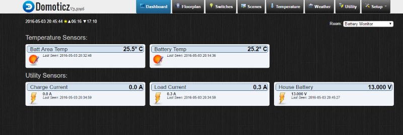
                                    Thanks @sundberg84 for this little board. I have just completed a sensor to monitor the state of our 12v house solar power supply.

                                    It uses an ACS712 Hall Effect Current Sensor Module to keep track of amps in and out of the battery. A voltage sensor to check battery levels and two DS18b20 temp sensors to monitor battery temp and ambient area temp. It reports back to our Domoticz server.
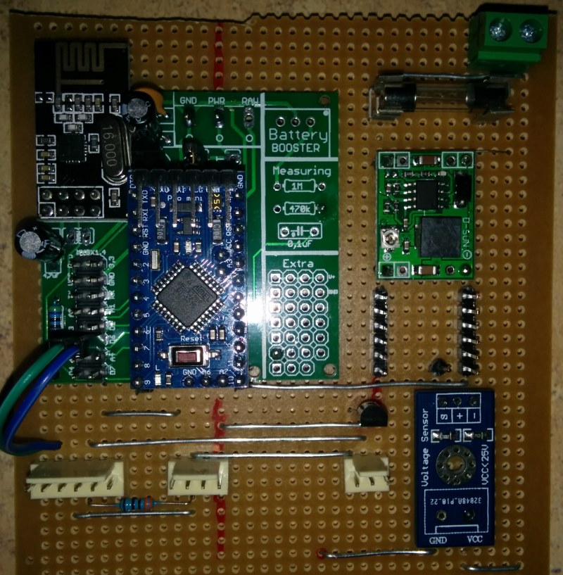
                                    0_1462273371700_board.jpg

                                    0_1462273409712_dom.jpg

                                    1 Reply Last reply
                                    3
                                    • sundberg84S sundberg84

                                      @Valle - yes you can just put a wire between left and right pin - but it wont work for a long time (the pro mini will die when battery goes below 3v i think).

                                      @nunver - I have never used this board as gateway. What does your controller say, does it apply an ID for the request?

                                      N Offline
                                      N Offline
                                      nunver
                                      wrote on last edited by
                                      #132

                                      @sundberg84 yes it gives an ID of 1, but somehow sensor keeps asking four more times. At the end of the cycle, no ID is set. So no sensor shown.

                                      sundberg84S 1 Reply Last reply
                                      0
                                      • N nunver

                                        @sundberg84 yes it gives an ID of 1, but somehow sensor keeps asking four more times. At the end of the cycle, no ID is set. So no sensor shown.

                                        sundberg84S Offline
                                        sundberg84S Offline
                                        sundberg84
                                        Hardware Contributor
                                        wrote on last edited by
                                        #133

                                        @nunver said:

                                        @sundberg84 yes it gives an ID of 1, but somehow sensor keeps asking four more times. At the end of the cycle, no ID is set. So no sensor shown.

                                        What does the log node say - find parent?
                                        This sounds like either software issue or most probably radio range/power issue,

                                        Controller: Proxmox VM - Home Assistant
                                        MySensors GW: Arduino Uno - W5100 Ethernet, Gw Shield Nrf24l01+ 2,4Ghz
                                        MySensors GW: Arduino Uno - Gw Shield RFM69, 433mhz
                                        RFLink GW - Arduino Mega + RFLink Shield, 433mhz

                                        1 Reply Last reply
                                        0
                                        • A Offline
                                          A Offline
                                          Affe
                                          wrote on last edited by
                                          #134

                                          Hello, I'm just finished with 3 cards and test . I read on mysensor.org I'll connect NRF24L01+ Radio whit decoupling capacitor of 47µF and on your card whit 4,7µF

                                          What is the difference?

                                          mfalkviddM 1 Reply Last reply
                                          0
                                          Reply
                                          • Reply as topic
                                          Log in to reply
                                          • Oldest to Newest
                                          • Newest to Oldest
                                          • Most Votes


                                          7

                                          Online

                                          11.7k

                                          Users

                                          11.2k

                                          Topics

                                          113.0k

                                          Posts


                                          Copyright 2019 TBD   |   Forum Guidelines   |   Privacy Policy   |   Terms of Service
                                          • Login

                                          • Don't have an account? Register

                                          • Login or register to search.
                                          • First post
                                            Last post
                                          0
                                          • MySensors
                                          • OpenHardware.io
                                          • Categories
                                          • Recent
                                          • Tags
                                          • Popular