💬 Easy/Newbie PCB for MySensors
-
@sundberg84 Thank you, just ordered some from ebay!
-
Hi Sundberg.
First of all thanks for what you have done here, and hi from New Zealand.
I have a problem though, sorry to be a hassle.
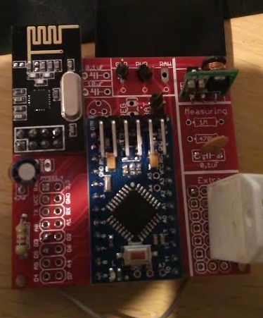
I assembled my first board tonight and I dont get 3.3v across the NRF. It starts at 0.07V then falls down to 0 on my cheap meter. Same on the MYSX1.4 connector at 3.3 and gnd. Am getting 3.3 on the mini as well as VCC and GND on the MYSX area so the regulator is working. May be a short? Or a bad solder? Although they look good to me.... If so what solder joints should I redo? Any other ideas?
Also, Ive traced back the VCC from the NRF and I cant see where it connects to a power source, either the battery in or the boost converter?
Thanks,
Matt -
Hi Sundberg.
First of all thanks for what you have done here, and hi from New Zealand.
I have a problem though, sorry to be a hassle.
I assembled my first board tonight and I dont get 3.3v across the NRF. It starts at 0.07V then falls down to 0 on my cheap meter. Same on the MYSX1.4 connector at 3.3 and gnd. Am getting 3.3 on the mini as well as VCC and GND on the MYSX area so the regulator is working. May be a short? Or a bad solder? Although they look good to me.... If so what solder joints should I redo? Any other ideas?
Also, Ive traced back the VCC from the NRF and I cant see where it connects to a power source, either the battery in or the boost converter?
Thanks,
Matt@Matt Hi Matt - tnx.
Try to measure here: whats your reading?
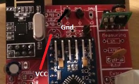
if its 3.3v its your radio thats has some error... this is prettu much the last point before radio. Also measure VCC/GND under the pcb and not on top, what does it say?Sounds like a short or bad solder...
-
@Matt Hi Matt - tnx.
Try to measure here: whats your reading?
if its 3.3v its your radio thats has some error... this is prettu much the last point before radio. Also measure VCC/GND under the pcb and not on top, what does it say?Sounds like a short or bad solder...
@sundberg84
Ah crikey I think Im being thick, I just put a jumper across BAT connectors after tracing the lines and reading the manual, am now getting 2.8 at the NRF. Sorry for being a numpty. Still not picking up on my gateway, time to go to bed but will get the serial monitor running tomorrow....
Thanks for the quick reply. -
I have a question about using this board as a gateway. Pinout of Mini Pro and Nano are almost identical. I built an adapter board to plug in a Nano into this board. Pin by pin control shows it is OK. I checked connectivity with MYSController. The gateway boots up. When I turn on my battery powered sensor, it asks for ID, the gateway "supposedly" sends it. I watch this from the messages. The sensor does not register. It asks four more times, the gateway responds four times. But sensor could not be ID'd and of course registered.
I am thinking either reception problem on sensor side, or transmission problem on gateway side? Could it be a power problem related with design of the board? Is there any way to identify?
Thanks
-
@Valle - yes you can just put a wire between left and right pin - but it wont work for a long time (the pro mini will die when battery goes below 3v i think).
@nunver - I have never used this board as gateway. What does your controller say, does it apply an ID for the request?
Controller: Proxmox VM - Home Assistant
MySensors GW: Arduino Uno - W5100 Ethernet, Gw Shield Nrf24l01+ 2,4Ghz
MySensors GW: Arduino Uno - Gw Shield RFM69, 433mhz
RFLink GW - Arduino Mega + RFLink Shield, 433mhz -
I'm using mfalkvidds Plant monitoring
mfalkvidd said:An update on battery life: The sensor in my bonsai tree has been reporting every 11,5 minutes since 2015-11-07, so over the last ~four months it has done 24,504 measurements. The battery level has gone from 3.187V to 3.142V, which means a drop of 0.01125V per month. Assuming I let it go down to 2.34V (limit for 8MHz according to the datasheet) and that the voltage drop is linear, I should get (3.187-2.34)/0.01125 = 75 months = ~6 years. There are several error sources in this calculation, but it looks like battery life will be quite good, even though the sensor reports much more often than necessary.
So I will try without Booster. But for other sensors I will use booster.
-
I'm using mfalkvidds Plant monitoring
mfalkvidd said:An update on battery life: The sensor in my bonsai tree has been reporting every 11,5 minutes since 2015-11-07, so over the last ~four months it has done 24,504 measurements. The battery level has gone from 3.187V to 3.142V, which means a drop of 0.01125V per month. Assuming I let it go down to 2.34V (limit for 8MHz according to the datasheet) and that the voltage drop is linear, I should get (3.187-2.34)/0.01125 = 75 months = ~6 years. There are several error sources in this calculation, but it looks like battery life will be quite good, even though the sensor reports much more often than necessary.
So I will try without Booster. But for other sensors I will use booster.
@Valle said:
So I will try without Booster. But for other sensors I will use booster.
Sounds good - let us know how it works out for you. 2,34V is for a genuine Arduino so you know - I dont think a clone manages that... also the last energy (from 1,9 to 2,34v) is not used even though the radio could handle it if you used a booster.
-
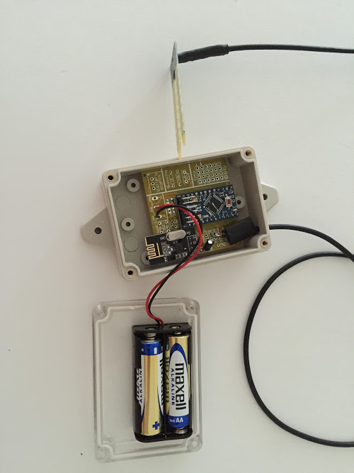
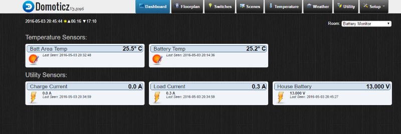
Thanks @sundberg84 for this little board. I have just completed a sensor to monitor the state of our 12v house solar power supply.
It uses an ACS712 Hall Effect Current Sensor Module to keep track of amps in and out of the battery. A voltage sensor to check battery levels and two DS18b20 temp sensors to monitor battery temp and ambient area temp. It reports back to our Domoticz server.
-
-
@sundberg84 yes it gives an ID of 1, but somehow sensor keeps asking four more times. At the end of the cycle, no ID is set. So no sensor shown.
@nunver said:
@sundberg84 yes it gives an ID of 1, but somehow sensor keeps asking four more times. At the end of the cycle, no ID is set. So no sensor shown.
What does the log node say - find parent?
This sounds like either software issue or most probably radio range/power issue, -
Hello, I'm just finished with 3 cards and test . I read on mysensor.org I'll connect NRF24L01+ Radio whit decoupling capacitor of 47µF and on your card whit 4,7µF
What is the difference?
-
Hello,
I just ordered from DirtyPCB.
Thank you very much for this board which will obviously save me a lot of time with the radio connection.
I'm planning to use the boards for :- as door+temp/humidity sensors for my children's bedrooms, not for the "security"/"safety" aspect but to manage AC more efficiently
- as window sensors for all windows in my appartment coupled with a rain sensor on the balcony, so I can ring an alarm/flash something/sens sms if it starts to rain and one of the windows is left opened. I'm in a tropical country and windows are opened most of the time, with the sudden and strong rains and winds we have sometime it can really be ugly :)
Power will most probably come from button cells and I will cut the right part of the PCB to fit in small and very cheap plastic boxes I find in shops here. I'm just waiting to see if the test sensor I have put on my entry door survives long enough with a CR2032.
-
Could you give me the size when the pcb is fully soldered as battery sensor?
-
@Nca78 - sounds great, let me know how it works out for you! Good luck!
@Rasenheizung - 50x50cm fully soldered. The dept is about 35mm (Batteryholder + PCB + Components)
-
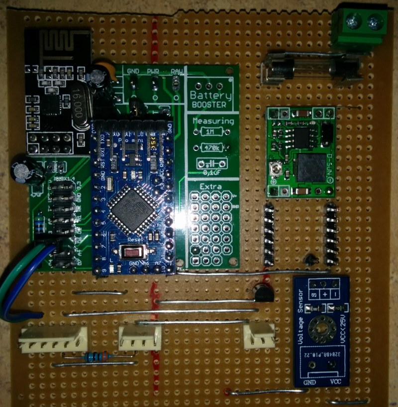
So - I have a question for the community about boosters. I had a 3.3v Arduino running with my PCB. The radio is connected directly to the battery and the rest through a booster. I experienced alot of st:fails.
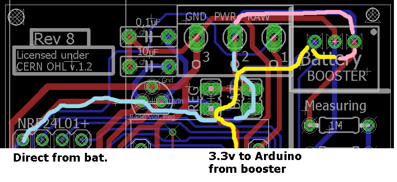
I tested adding a 0.1uF cap on the booster from OUT to GND and the st:fails became st:ok, even though the radio does not get its power from this booster.
Im sure the boosters are in different qualities and renders alot of noice - but could it effect the radio - through the arduino?
If this continues Im going to add the possibility to add this cap on my PCB. (Or maybe its possible to use 0.1uF cap by the voltage divider...)Any feedback ?
Controller: Proxmox VM - Home Assistant
MySensors GW: Arduino Uno - W5100 Ethernet, Gw Shield Nrf24l01+ 2,4Ghz
MySensors GW: Arduino Uno - Gw Shield RFM69, 433mhz
RFLink GW - Arduino Mega + RFLink Shield, 433mhz -
So - I have a question for the community about boosters. I had a 3.3v Arduino running with my PCB. The radio is connected directly to the battery and the rest through a booster. I experienced alot of st:fails.
I tested adding a 0.1uF cap on the booster from OUT to GND and the st:fails became st:ok, even though the radio does not get its power from this booster.
Im sure the boosters are in different qualities and renders alot of noice - but could it effect the radio - through the arduino?
If this continues Im going to add the possibility to add this cap on my PCB. (Or maybe its possible to use 0.1uF cap by the voltage divider...)Any feedback ?
@sundberg84 typically, I try to add the lc-filter to the booster as some of them are very noisy. This is very simple - 3.3µH Axial lead inducter and a large 220µF capacitor (I use the SMD version). This helps to smooth any ripple effect.
-
Any sort of manipulation, including regulators and boosters, added to any module i would always attempt to filter and smooth the input AND the output of the devices. The noise from the boosters would technically be reaching your radio from those traces. I'm not sure if a diode would stop it from feeding back to the radio, but either way if it did i would still prefer to smooth and filter the power instead of stopping it coming backwards.