Skip to content
  • MySensors
  • OpenHardware.io
  • Categories
  • Recent
  • Tags
  • Popular
Skins
  • Light
  • Brite
  • Cerulean
  • Cosmo
  • Flatly
  • Journal
  • Litera
  • Lumen
  • Lux
  • Materia
  • Minty
  • Morph
  • Pulse
  • Sandstone
  • Simplex
  • Sketchy
  • Spacelab
  • United
  • Yeti
  • Zephyr
  • Dark
  • Cyborg
  • Darkly
  • Quartz
  • Slate
  • Solar
  • Superhero
  • Vapor

  • Default (No Skin)
  • No Skin
Collapse
Brand Logo
  1. Home
  2. OpenHardware.io
  3. 💬 Easy/Newbie PCB for MySensors

💬 Easy/Newbie PCB for MySensors

Scheduled Pinned Locked Moved OpenHardware.io
mysensorsbatteryeasynewbiepcbmysx
716 Posts 111 Posters 306.1k Views 93 Watching
  • Oldest to Newest
  • Newest to Oldest
  • Most Votes
Reply
  • Reply as topic
Log in to reply
This topic has been deleted. Only users with topic management privileges can see it.
  • cmrockwellC cmrockwell

    @sundberg84
    OK, I figured out how to do what I wanted. I am planning to connect a regulated power supply that provides ~3.3VDC. The main thing I had to figure out was how to configure the PCB when neither a battery booster nor a regulator are needed. I think either shorting the REG pin and shorting the regulator or shorting the BAT pin and shorting the battery booster would each achieve the desired result.

    sundberg84S Offline
    sundberg84S Offline
    sundberg84
    Hardware Contributor
    wrote on last edited by
    #288

    @cmrockwell - well done!
    Yes, digging deeper into it you can probably hack it many ways with jumpers and wires.

    Controller: Proxmox VM - Home Assistant
    MySensors GW: Arduino Uno - W5100 Ethernet, Gw Shield Nrf24l01+ 2,4Ghz
    MySensors GW: Arduino Uno - Gw Shield RFM69, 433mhz
    RFLink GW - Arduino Mega + RFLink Shield, 433mhz

    1 Reply Last reply
    0
    • gohanG Offline
      gohanG Offline
      gohan
      Mod
      wrote on last edited by
      #289

      If I want to use a mini pro 3.3v and a 18650 battery that I have lying around, should I use something like THIS or do you think there is a better/more efficient way?

      sundberg84S 1 Reply Last reply
      0
      • gohanG gohan

        If I want to use a mini pro 3.3v and a 18650 battery that I have lying around, should I use something like THIS or do you think there is a better/more efficient way?

        sundberg84S Offline
        sundberg84S Offline
        sundberg84
        Hardware Contributor
        wrote on last edited by
        #290

        @gohan - im not that good in efficiency in boosters and converting voltage. Im sure that would work! The main thing is 1) deliver correct voltage and 2) if they are to noicy they will interfere with the radio and make the communication fail.

        Controller: Proxmox VM - Home Assistant
        MySensors GW: Arduino Uno - W5100 Ethernet, Gw Shield Nrf24l01+ 2,4Ghz
        MySensors GW: Arduino Uno - Gw Shield RFM69, 433mhz
        RFLink GW - Arduino Mega + RFLink Shield, 433mhz

        1 Reply Last reply
        0
        • P Offline
          P Offline
          popunonkok
          wrote on last edited by
          #291

          I having trouble to order this board from DirtyPCB.
          Both the link in the beginning of this thread (Rev8) and the link in the OpenHarware page just directs me to an empty DirtyPCB order page, with no board preloaded. It wants me to upload files.
          Does anyone know how to order from DirtyPcb without uploading the boardfiles?

          sundberg84S 1 Reply Last reply
          0
          • P popunonkok

            I having trouble to order this board from DirtyPCB.
            Both the link in the beginning of this thread (Rev8) and the link in the OpenHarware page just directs me to an empty DirtyPCB order page, with no board preloaded. It wants me to upload files.
            Does anyone know how to order from DirtyPcb without uploading the boardfiles?

            sundberg84S Offline
            sundberg84S Offline
            sundberg84
            Hardware Contributor
            wrote on last edited by sundberg84
            #292

            @popunonkok - the link to DirtyPCB is not posted or maintained by me. If you want the latest revisions please go to order under openhardware.io = https://www.openhardware.io/order/4/PCB10X. DirtyPCB is not an option there so if you want to use them you need to download the gerberfiles for the project = https://www.openhardware.io/view/4/EasyNewbie-PCB-for-MySensors#tabs-design and upload them according to their instructions = http://dirtypcbs.com/store/pcbs/about (see order)

            Controller: Proxmox VM - Home Assistant
            MySensors GW: Arduino Uno - W5100 Ethernet, Gw Shield Nrf24l01+ 2,4Ghz
            MySensors GW: Arduino Uno - Gw Shield RFM69, 433mhz
            RFLink GW - Arduino Mega + RFLink Shield, 433mhz

            1 Reply Last reply
            0
            • P Offline
              P Offline
              popunonkok
              wrote on last edited by
              #293

              Iv just orderd Rev8.

              I have a primary question, might have a couple more later on.
              In the info about the board it says:

              "BAT: Short this if you are using batteries as power supply. It will activate booster circuit and feed the radio directly from the batteries and not voltage regulator"

              It says about the same on the image of the board.

              My question is. Why would I want to powewr the radio directly from battery and not from the Booster? Wouldent that make the radio not to function like it sould when the voltage dropps?

              sundberg84S 1 Reply Last reply
              0
              • P popunonkok

                Iv just orderd Rev8.

                I have a primary question, might have a couple more later on.
                In the info about the board it says:

                "BAT: Short this if you are using batteries as power supply. It will activate booster circuit and feed the radio directly from the batteries and not voltage regulator"

                It says about the same on the image of the board.

                My question is. Why would I want to powewr the radio directly from battery and not from the Booster? Wouldent that make the radio not to function like it sould when the voltage dropps?

                sundberg84S Offline
                sundberg84S Offline
                sundberg84
                Hardware Contributor
                wrote on last edited by
                #294

                @popunonkok - if you search the forum and this thread about noice in the boosters you will find a big search result. The boosters is, to be honest, pretty bad. They generate alot of noice which interfere with the radio which is pretty sensitive. By "learning by doing" we have figured out that if you are using a booster the best way is to provice power to the radio directly from the batteries to avoid the noice... the radio will pretty much fail if you dont.

                The radio can handle down to 1.9 v so this will be your minimum voltage for the circiut.

                Controller: Proxmox VM - Home Assistant
                MySensors GW: Arduino Uno - W5100 Ethernet, Gw Shield Nrf24l01+ 2,4Ghz
                MySensors GW: Arduino Uno - Gw Shield RFM69, 433mhz
                RFLink GW - Arduino Mega + RFLink Shield, 433mhz

                1 Reply Last reply
                1
                • P Offline
                  P Offline
                  popunonkok
                  wrote on last edited by
                  #295

                  Hmmm... Ok...

                  I had only read that the boosters helpt to drain the battery completely, had missed that they "messed" with the radio.

                  It will be really interesting to see what kind of battery life I can get out of 2 or 4 AA batteries on different types of nodes.

                  When I look at the Specs for the Pro Mini board the supply voltage is 3.35 - 12v.
                  I guess that means that without a Booster 2 AA batteries wont be able to run the Pro mini for a long time at all.

                  sundberg84S 1 Reply Last reply
                  0
                  • P popunonkok

                    Hmmm... Ok...

                    I had only read that the boosters helpt to drain the battery completely, had missed that they "messed" with the radio.

                    It will be really interesting to see what kind of battery life I can get out of 2 or 4 AA batteries on different types of nodes.

                    When I look at the Specs for the Pro Mini board the supply voltage is 3.35 - 12v.
                    I guess that means that without a Booster 2 AA batteries wont be able to run the Pro mini for a long time at all.

                    sundberg84S Offline
                    sundberg84S Offline
                    sundberg84
                    Hardware Contributor
                    wrote on last edited by sundberg84
                    #296

                    @popunonkok - you are correct, they are good for they "suck all the juice" out of the batteries. Without modifications the Pro Mini 3.3v have a lowerst voltage of 2.8V (called Brown out detection) Because of that when you use 2xAA you need the booster to keep a stable 3.3v and most of the booster can convert everyhing down to 0.9v back to 3.3v. The radio can handle down to 1.9v and that will be your lowerst point.

                    I have nodes reading temp and humidity with a dht22 every 15min, running this setup and they last around 1 year each.
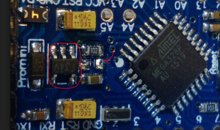
                    You need to search the forum and https://www.mysensors.org/build/battery for power saving with battery. The most common first step is to remove the voltage regulator and the led. Then you sleep the node when it isnt active.

                    On this image you see the led removed (red arrow). I think its easier to remove the resistor (black circle, marked 102) but its the same result. Voltage regulater (red circle) is removed as well. Note that many sites say cut the trace but its much easier to desolder them.

                    0_1488381852786_1.JPG

                    Using the internal voltage regulator (3.35 - 12v) will kill the node in weeks/days if you run them on 2-4xAA because of the high current drain. My aim building a newbie/easy PCB is a sleepcurrent of 0,1mA or 100uA.

                    Controller: Proxmox VM - Home Assistant
                    MySensors GW: Arduino Uno - W5100 Ethernet, Gw Shield Nrf24l01+ 2,4Ghz
                    MySensors GW: Arduino Uno - Gw Shield RFM69, 433mhz
                    RFLink GW - Arduino Mega + RFLink Shield, 433mhz

                    1 Reply Last reply
                    0
                    • chrlyraC Offline
                      chrlyraC Offline
                      chrlyra
                      wrote on last edited by
                      #297

                      hi there,

                      Thanks for the easypcb! I'm trying to build a small solar powered weather station (like these: https://forum.mysensors.org/topic/841/solar-powered-mini-weather-station), but just found that the battery that came with the solar panel only provides 1.2v. The booster works ok and I can power the arduino, but it's no enough for the radio :-(. Since powering the radio from the booster is not a option, I'm at a dead end. Or there's a way to still using this battery/solar panel?

                      sundberg84S gohanG 2 Replies Last reply
                      0
                      • chrlyraC chrlyra

                        hi there,

                        Thanks for the easypcb! I'm trying to build a small solar powered weather station (like these: https://forum.mysensors.org/topic/841/solar-powered-mini-weather-station), but just found that the battery that came with the solar panel only provides 1.2v. The booster works ok and I can power the arduino, but it's no enough for the radio :-(. Since powering the radio from the booster is not a option, I'm at a dead end. Or there's a way to still using this battery/solar panel?

                        sundberg84S Offline
                        sundberg84S Offline
                        sundberg84
                        Hardware Contributor
                        wrote on last edited by
                        #298

                        @chrlyra - you need 1.9V minimum for the radio. There are more advanced boosters you could try which probably is better and less noice... but this PCB was not designed for that purpose so sorry, I cant help you.

                        Controller: Proxmox VM - Home Assistant
                        MySensors GW: Arduino Uno - W5100 Ethernet, Gw Shield Nrf24l01+ 2,4Ghz
                        MySensors GW: Arduino Uno - Gw Shield RFM69, 433mhz
                        RFLink GW - Arduino Mega + RFLink Shield, 433mhz

                        1 Reply Last reply
                        0
                        • chrlyraC chrlyra

                          hi there,

                          Thanks for the easypcb! I'm trying to build a small solar powered weather station (like these: https://forum.mysensors.org/topic/841/solar-powered-mini-weather-station), but just found that the battery that came with the solar panel only provides 1.2v. The booster works ok and I can power the arduino, but it's no enough for the radio :-(. Since powering the radio from the booster is not a option, I'm at a dead end. Or there's a way to still using this battery/solar panel?

                          gohanG Offline
                          gohanG Offline
                          gohan
                          Mod
                          wrote on last edited by
                          #299

                          @chrlyra
                          There is another project called solar harvester that uses a supercap to store energy

                          1 Reply Last reply
                          1
                          • dbemowskD Offline
                            dbemowskD Offline
                            dbemowsk
                            wrote on last edited by
                            #300

                            So a question I have always wondered about the voltage regulator is do you really need to desolder it if you connect your incoming power to the 3.3v pin and not the RAW pin? I would have thought the regulator would only drain power if it was converting the RAW power down to 3.3v.

                            Vera Plus running UI7 with MySensors, Sonoffs and 1-Wire devices
                            Visit my website for more Bits, Bytes and Ramblings from me: http://dan.bemowski.info/

                            sundberg84S Nca78N 2 Replies Last reply
                            0
                            • dbemowskD dbemowsk

                              So a question I have always wondered about the voltage regulator is do you really need to desolder it if you connect your incoming power to the 3.3v pin and not the RAW pin? I would have thought the regulator would only drain power if it was converting the RAW power down to 3.3v.

                              sundberg84S Offline
                              sundberg84S Offline
                              sundberg84
                              Hardware Contributor
                              wrote on last edited by
                              #301

                              @dbemowsk - your logic sounds right, but i think it will draw power anyway... only way to figure out is to measure or google :)

                              Controller: Proxmox VM - Home Assistant
                              MySensors GW: Arduino Uno - W5100 Ethernet, Gw Shield Nrf24l01+ 2,4Ghz
                              MySensors GW: Arduino Uno - Gw Shield RFM69, 433mhz
                              RFLink GW - Arduino Mega + RFLink Shield, 433mhz

                              1 Reply Last reply
                              0
                              • P Offline
                                P Offline
                                popunonkok
                                wrote on last edited by popunonkok
                                #302

                                I managed to change my PCB order, I saw that one of the updates to rev9 was the ability to use Pin 2 as GPIO instead of going to the Radio where it is unused. So now I have a order for Rev9 instead.

                                I will try to desolder the led or resistor and the voltageregulator.

                                Thanks for sharing your design.

                                sundberg84S 1 Reply Last reply
                                0
                                • P popunonkok

                                  I managed to change my PCB order, I saw that one of the updates to rev9 was the ability to use Pin 2 as GPIO instead of going to the Radio where it is unused. So now I have a order for Rev9 instead.

                                  I will try to desolder the led or resistor and the voltageregulator.

                                  Thanks for sharing your design.

                                  sundberg84S Offline
                                  sundberg84S Offline
                                  sundberg84
                                  Hardware Contributor
                                  wrote on last edited by
                                  #303

                                  @popunonkok Good luck - let me know if there is any other questions.

                                  Controller: Proxmox VM - Home Assistant
                                  MySensors GW: Arduino Uno - W5100 Ethernet, Gw Shield Nrf24l01+ 2,4Ghz
                                  MySensors GW: Arduino Uno - Gw Shield RFM69, 433mhz
                                  RFLink GW - Arduino Mega + RFLink Shield, 433mhz

                                  1 Reply Last reply
                                  1
                                  • dbemowskD dbemowsk

                                    So a question I have always wondered about the voltage regulator is do you really need to desolder it if you connect your incoming power to the 3.3v pin and not the RAW pin? I would have thought the regulator would only drain power if it was converting the RAW power down to 3.3v.

                                    Nca78N Offline
                                    Nca78N Offline
                                    Nca78
                                    Hardware Contributor
                                    wrote on last edited by
                                    #304

                                    @dbemowsk in fact current is leaking through the regulator when its input is floating, you can check the "reverse leakage current" value on the data sheet of the linear regulator used on your promini boards then decide if you can accept it or not, depending on your circuit.

                                    1 Reply Last reply
                                    2
                                    • ileneken3I Offline
                                      ileneken3I Offline
                                      ileneken3
                                      wrote on last edited by
                                      #305

                                      Hi -

                                      I wanted to know if this config is OK:

                                      Attach a LIPO battery to PWR and GND.
                                      Cut off the right side of the board.
                                      Use a 3.3V pro mini.
                                      Add a regulator (like a MCP1700) and necessary caps. (Spec says 1uF).

                                      The idea is that the board and sensors get 3.2V - 4.1 V (which should be OK).
                                      The radio gets 3.3V.

                                      Thanks!

                                      sundberg84S 1 Reply Last reply
                                      0
                                      • ileneken3I ileneken3

                                        Hi -

                                        I wanted to know if this config is OK:

                                        Attach a LIPO battery to PWR and GND.
                                        Cut off the right side of the board.
                                        Use a 3.3V pro mini.
                                        Add a regulator (like a MCP1700) and necessary caps. (Spec says 1uF).

                                        The idea is that the board and sensors get 3.2V - 4.1 V (which should be OK).
                                        The radio gets 3.3V.

                                        Thanks!

                                        sundberg84S Offline
                                        sundberg84S Offline
                                        sundberg84
                                        Hardware Contributor
                                        wrote on last edited by sundberg84
                                        #306

                                        @ileneken3 - sounds right, you should short the jumper REG which will feed everything the LIPO voltage. If this is higher than 3.3v I dont know what will happen but adding the voltage regulator for the radio will make sure that one is ok. I dont know about the pro mini, it it can handle up to 4.1v but I guess you will find out.

                                        Controller: Proxmox VM - Home Assistant
                                        MySensors GW: Arduino Uno - W5100 Ethernet, Gw Shield Nrf24l01+ 2,4Ghz
                                        MySensors GW: Arduino Uno - Gw Shield RFM69, 433mhz
                                        RFLink GW - Arduino Mega + RFLink Shield, 433mhz

                                        1 Reply Last reply
                                        0
                                        • gohanG Offline
                                          gohanG Offline
                                          gohan
                                          Mod
                                          wrote on last edited by
                                          #307

                                          I'm curious too if will handle the 4 volts or not😀

                                          1 Reply Last reply
                                          0
                                          Reply
                                          • Reply as topic
                                          Log in to reply
                                          • Oldest to Newest
                                          • Newest to Oldest
                                          • Most Votes


                                          8

                                          Online

                                          11.7k

                                          Users

                                          11.2k

                                          Topics

                                          113.0k

                                          Posts


                                          Copyright 2019 TBD   |   Forum Guidelines   |   Privacy Policy   |   Terms of Service
                                          • Login

                                          • Don't have an account? Register

                                          • Login or register to search.
                                          • First post
                                            Last post
                                          0
                                          • MySensors
                                          • OpenHardware.io
                                          • Categories
                                          • Recent
                                          • Tags
                                          • Popular