Skip to content
  • MySensors
  • OpenHardware.io
  • Categories
  • Recent
  • Tags
  • Popular
Skins
  • Light
  • Brite
  • Cerulean
  • Cosmo
  • Flatly
  • Journal
  • Litera
  • Lumen
  • Lux
  • Materia
  • Minty
  • Morph
  • Pulse
  • Sandstone
  • Simplex
  • Sketchy
  • Spacelab
  • United
  • Yeti
  • Zephyr
  • Dark
  • Cyborg
  • Darkly
  • Quartz
  • Slate
  • Solar
  • Superhero
  • Vapor

  • Default (No Skin)
  • No Skin
Collapse
Brand Logo
  1. Home
  2. OpenHardware.io
  3. 💬 Easy/Newbie PCB for MySensors

💬 Easy/Newbie PCB for MySensors

Scheduled Pinned Locked Moved OpenHardware.io
mysensorsbatteryeasynewbiepcbmysx
716 Posts 111 Posters 306.2k Views 93 Watching
  • Oldest to Newest
  • Newest to Oldest
  • Most Votes
Reply
  • Reply as topic
Log in to reply
This topic has been deleted. Only users with topic management privileges can see it.
  • gohanG gohan

    @hiddenuser I'm missing how can you use a booster to get 3.3v from a lipo battery

    H Offline
    H Offline
    hiddenuser
    wrote on last edited by
    #457

    @gohan @sundberg84
    This is my setup. my battery reading is a constant 2.75v, this is not true the multi meter says ~4v

    0_1513062564871_IMG_20171212_180306_1.jpg

    sundberg84S gohanG 2 Replies Last reply
    0
    • markjgabbM markjgabb

      @dbemowsk cheers mate, thats awesome...now i can blitz out some room based designs

      sundberg84S Offline
      sundberg84S Offline
      sundberg84
      Hardware Contributor
      wrote on last edited by
      #458

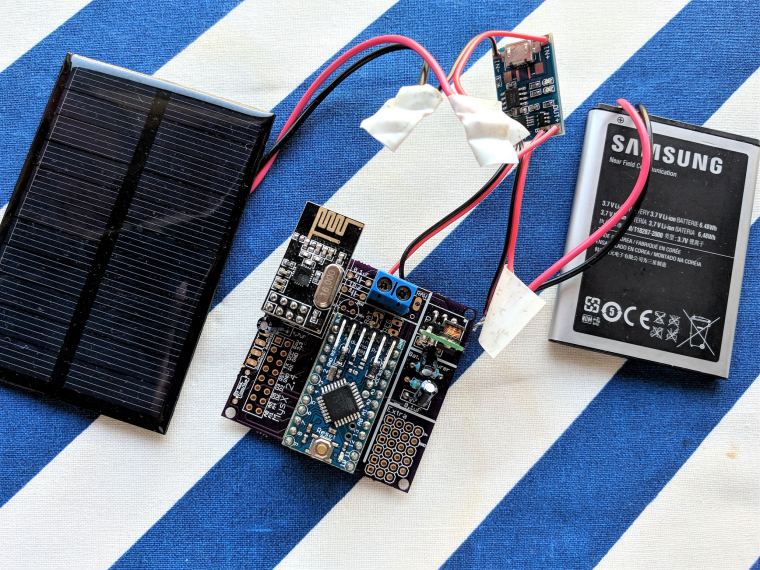
      @markjgabb @dbemowsk @gohan - I dont have much else to add, thanks for the input here. Using mains power I would also use HLK-PM01 and input the 5v to the pro mini. If you only have 3.3v pro mini you need to input this to RAW. I have made a breakout board for the HLK module if needed as well.

      https://www.openhardware.io/view/504/HLK-PM01-breakout-board

      Controller: Proxmox VM - Home Assistant
      MySensors GW: Arduino Uno - W5100 Ethernet, Gw Shield Nrf24l01+ 2,4Ghz
      MySensors GW: Arduino Uno - Gw Shield RFM69, 433mhz
      RFLink GW - Arduino Mega + RFLink Shield, 433mhz

      1 Reply Last reply
      0
      • H hiddenuser

        @gohan @sundberg84
        This is my setup. my battery reading is a constant 2.75v, this is not true the multi meter says ~4v

        0_1513062564871_IMG_20171212_180306_1.jpg

        sundberg84S Offline
        sundberg84S Offline
        sundberg84
        Hardware Contributor
        wrote on last edited by sundberg84
        #459

        Well it looks like your battery goes to some sort of regulator before the Easy board? If so my guess is that that board is providing 2.7 v regardless of battery voltage? Have a look at @gohan and his posts about solar power and different batteries. EasyPCB is designed for 2xAA and it will not work with other voltages out of the box. The voltage divider is also dimensioned for 3.3v max and will not work with higher voltages. Again @gohan has made some experiments with this. Check his posts out. If you re-dimension the voltage divider it will work with your higher voltage.

        Controller: Proxmox VM - Home Assistant
        MySensors GW: Arduino Uno - W5100 Ethernet, Gw Shield Nrf24l01+ 2,4Ghz
        MySensors GW: Arduino Uno - Gw Shield RFM69, 433mhz
        RFLink GW - Arduino Mega + RFLink Shield, 433mhz

        1 Reply Last reply
        0
        • H hiddenuser

          @gohan @sundberg84
          This is my setup. my battery reading is a constant 2.75v, this is not true the multi meter says ~4v

          0_1513062564871_IMG_20171212_180306_1.jpg

          gohanG Offline
          gohanG Offline
          gohan
          Mod
          wrote on last edited by
          #460

          @hiddenuser I don't know why you have a booster in place (unless it is a buck boost) and you need to change the voltage divider resistors if you want to read higher voltages (look at my solar project). In addition I'd put in place a LDO regulator if you want to use a lipo battery since a normal voltage regulator would require a higher Vin than a lipo battery can provide.

          H 1 Reply Last reply
          0
          • gohanG gohan

            @hiddenuser I don't know why you have a booster in place (unless it is a buck boost) and you need to change the voltage divider resistors if you want to read higher voltages (look at my solar project). In addition I'd put in place a LDO regulator if you want to use a lipo battery since a normal voltage regulator would require a higher Vin than a lipo battery can provide.

            H Offline
            H Offline
            hiddenuser
            wrote on last edited by hiddenuser
            #461

            @gohan said in 💬 Easy/Newbie PCB for MySensors:

            Thanks @gohan for the feedback. Can I have the link to your solar project!

            gohanG 1 Reply Last reply
            0
            • H hiddenuser

              @gohan said in 💬 Easy/Newbie PCB for MySensors:

              Thanks @gohan for the feedback. Can I have the link to your solar project!

              gohanG Offline
              gohanG Offline
              gohan
              Mod
              wrote on last edited by
              #462

              @hiddenuser look in the my project section (I'm on mobile now)

              1 Reply Last reply
              0
              • BarnaB Offline
                BarnaB Offline
                Barna
                wrote on last edited by
                #463

                Hi Sundberg,

                I have read there could be some problem about radio connection if the temperature is ~0C or minus, I have met this issue so I will replace the existing 4.7µ capacitor with a bigger, e.g. ~20µ.
                The battery measurement contains a 0.1 uF capacitor, What do you think I do have to replace it with an another bigger one ?
                thanks

                Barna

                sundberg84S dbemowskD Nca78N 3 Replies Last reply
                0
                • BarnaB Barna

                  Hi Sundberg,

                  I have read there could be some problem about radio connection if the temperature is ~0C or minus, I have met this issue so I will replace the existing 4.7µ capacitor with a bigger, e.g. ~20µ.
                  The battery measurement contains a 0.1 uF capacitor, What do you think I do have to replace it with an another bigger one ?
                  thanks

                  Barna

                  sundberg84S Offline
                  sundberg84S Offline
                  sundberg84
                  Hardware Contributor
                  wrote on last edited by
                  #464

                  @barna - i don't know to be honest. As I wrote I had issues last winter but never with that 0.1 cap. I'm running second winter now (have been as low as -8C so far) without issues.

                  Controller: Proxmox VM - Home Assistant
                  MySensors GW: Arduino Uno - W5100 Ethernet, Gw Shield Nrf24l01+ 2,4Ghz
                  MySensors GW: Arduino Uno - Gw Shield RFM69, 433mhz
                  RFLink GW - Arduino Mega + RFLink Shield, 433mhz

                  1 Reply Last reply
                  0
                  • BarnaB Barna

                    Hi Sundberg,

                    I have read there could be some problem about radio connection if the temperature is ~0C or minus, I have met this issue so I will replace the existing 4.7µ capacitor with a bigger, e.g. ~20µ.
                    The battery measurement contains a 0.1 uF capacitor, What do you think I do have to replace it with an another bigger one ?
                    thanks

                    Barna

                    dbemowskD Offline
                    dbemowskD Offline
                    dbemowsk
                    wrote on last edited by
                    #465

                    @barna check out this thread:
                    https://forum.mysensors.org/topic/186/new-library-to-read-arduino-vcc-supply-level-without-resistors-for-battery-powered-sensor-nodes-that-do-not-use-a-voltage-regulator-but-connect-directly-to-the-batteries
                    It is a way to monitor battery voltage without the need for the 0.1 uf capacitor and resistor setup on the board.

                    Vera Plus running UI7 with MySensors, Sonoffs and 1-Wire devices
                    Visit my website for more Bits, Bytes and Ramblings from me: http://dan.bemowski.info/

                    1 Reply Last reply
                    0
                    • BarnaB Barna

                      Hi Sundberg,

                      I have read there could be some problem about radio connection if the temperature is ~0C or minus, I have met this issue so I will replace the existing 4.7µ capacitor with a bigger, e.g. ~20µ.
                      The battery measurement contains a 0.1 uF capacitor, What do you think I do have to replace it with an another bigger one ?
                      thanks

                      Barna

                      Nca78N Offline
                      Nca78N Offline
                      Nca78
                      Hardware Contributor
                      wrote on last edited by
                      #466

                      @barna said in 💬 Easy/Newbie PCB for MySensors:

                      Hi Sundberg,

                      I have read there could be some problem about radio connection if the temperature is ~0C or minus, I have met this issue so I will replace the existing 4.7µ capacitor with a bigger, e.g. ~20µ.
                      The battery measurement contains a 0.1 uF capacitor, What do you think I do have to replace it with an another bigger one ?
                      thanks

                      Barna

                      I don't think you need, it's made to stabilize the measured voltage, in the worst case the measured voltage will be a little bit unstable but your node will still run fine.

                      1 Reply Last reply
                      0
                      • markjgabbM Offline
                        markjgabbM Offline
                        markjgabb
                        wrote on last edited by
                        #467

                        on the subject of batteries i have to say im really impressed with the setup of these boards....
                        ive got a DHT and lux resistor measuring every 10 minutes, and i cant even remember how long ago i last changed the batteries...i think its about 3-4 months now....nothing special, just aldi batteries (australian cheap shopping chain)

                        last check they are still 65%

                        dbemowskD 1 Reply Last reply
                        1
                        • markjgabbM markjgabb

                          on the subject of batteries i have to say im really impressed with the setup of these boards....
                          ive got a DHT and lux resistor measuring every 10 minutes, and i cant even remember how long ago i last changed the batteries...i think its about 3-4 months now....nothing special, just aldi batteries (australian cheap shopping chain)

                          last check they are still 65%

                          dbemowskD Offline
                          dbemowskD Offline
                          dbemowsk
                          wrote on last edited by
                          #468

                          @markjgabb Don't know if it's the same chain, but we have aldi stores here in the US.
                          0_1513550068757_11f86073-b6bf-40a7-be80-0b6115b268af-image.png

                          Vera Plus running UI7 with MySensors, Sonoffs and 1-Wire devices
                          Visit my website for more Bits, Bytes and Ramblings from me: http://dan.bemowski.info/

                          M 1 Reply Last reply
                          0
                          • dbemowskD dbemowsk

                            @markjgabb Don't know if it's the same chain, but we have aldi stores here in the US.
                            0_1513550068757_11f86073-b6bf-40a7-be80-0b6115b268af-image.png

                            M Offline
                            M Offline
                            marvin78
                            wrote on last edited by
                            #469

                            @dbemowsk It is. It's a german chain though ;)

                            dbemowskD 1 Reply Last reply
                            1
                            • M marvin78

                              @dbemowsk It is. It's a german chain though ;)

                              dbemowskD Offline
                              dbemowskD Offline
                              dbemowsk
                              wrote on last edited by
                              #470

                              @marvin78 Never knew that.

                              Vera Plus running UI7 with MySensors, Sonoffs and 1-Wire devices
                              Visit my website for more Bits, Bytes and Ramblings from me: http://dan.bemowski.info/

                              1 Reply Last reply
                              0
                              • A Offline
                                A Offline
                                akamap
                                wrote on last edited by
                                #471

                                Hi everybody. Finally got my newb pcb and I soldered everything needed for the pro mini 3.3v. But I ran into problems.

                                I think it's the cheap chinese pdo mini but I want to ask you guys. Problem id that my node doesn't work. But when I debug my node I plug my pro mini in my computer's usb and then it works.

                                What I could see is that when it is battery operated I can read a 3.3v value on the vcc pin of the pro mini. When I also connect via usb this value is about 3.5v.

                                Could it be that my pro mini requires 3.5v.
                                I did solder the capacitor for the radio and i'm using a 3.3v step up converter also.

                                Thank you

                                dbemowskD gohanG 2 Replies Last reply
                                0
                                • A akamap

                                  Hi everybody. Finally got my newb pcb and I soldered everything needed for the pro mini 3.3v. But I ran into problems.

                                  I think it's the cheap chinese pdo mini but I want to ask you guys. Problem id that my node doesn't work. But when I debug my node I plug my pro mini in my computer's usb and then it works.

                                  What I could see is that when it is battery operated I can read a 3.3v value on the vcc pin of the pro mini. When I also connect via usb this value is about 3.5v.

                                  Could it be that my pro mini requires 3.5v.
                                  I did solder the capacitor for the radio and i'm using a 3.3v step up converter also.

                                  Thank you

                                  dbemowskD Offline
                                  dbemowskD Offline
                                  dbemowsk
                                  wrote on last edited by
                                  #472

                                  @akamap an you post a picture of your board setup?

                                  Vera Plus running UI7 with MySensors, Sonoffs and 1-Wire devices
                                  Visit my website for more Bits, Bytes and Ramblings from me: http://dan.bemowski.info/

                                  1 Reply Last reply
                                  0
                                  • A akamap

                                    Hi everybody. Finally got my newb pcb and I soldered everything needed for the pro mini 3.3v. But I ran into problems.

                                    I think it's the cheap chinese pdo mini but I want to ask you guys. Problem id that my node doesn't work. But when I debug my node I plug my pro mini in my computer's usb and then it works.

                                    What I could see is that when it is battery operated I can read a 3.3v value on the vcc pin of the pro mini. When I also connect via usb this value is about 3.5v.

                                    Could it be that my pro mini requires 3.5v.
                                    I did solder the capacitor for the radio and i'm using a 3.3v step up converter also.

                                    Thank you

                                    gohanG Offline
                                    gohanG Offline
                                    gohan
                                    Mod
                                    wrote on last edited by
                                    #473

                                    @akamap without knowing how you are powering the node, it is difficult to say.

                                    sundberg84S 1 Reply Last reply
                                    0
                                    • gohanG gohan

                                      @akamap without knowing how you are powering the node, it is difficult to say.

                                      sundberg84S Offline
                                      sundberg84S Offline
                                      sundberg84
                                      Hardware Contributor
                                      wrote on last edited by sundberg84
                                      #474

                                      @akamap - listen to the guys above, let us know with pictures :) Its the best.
                                      Did you by any chance miss to solder to jumpers?
                                      The best approach is to measure with a multimeter... put the black to GND and measure your way through the circuit from batteries, booster, jumper, pro mini and radio with the red put on each components VCC (or Vout on booster). Then you know where it goes wrong. Try to follow the schematics or the traces in the pcb to figure out how the current flows.

                                      Controller: Proxmox VM - Home Assistant
                                      MySensors GW: Arduino Uno - W5100 Ethernet, Gw Shield Nrf24l01+ 2,4Ghz
                                      MySensors GW: Arduino Uno - Gw Shield RFM69, 433mhz
                                      RFLink GW - Arduino Mega + RFLink Shield, 433mhz

                                      dbemowskD 1 Reply Last reply
                                      0
                                      • sundberg84S sundberg84

                                        @akamap - listen to the guys above, let us know with pictures :) Its the best.
                                        Did you by any chance miss to solder to jumpers?
                                        The best approach is to measure with a multimeter... put the black to GND and measure your way through the circuit from batteries, booster, jumper, pro mini and radio with the red put on each components VCC (or Vout on booster). Then you know where it goes wrong. Try to follow the schematics or the traces in the pcb to figure out how the current flows.

                                        dbemowskD Offline
                                        dbemowskD Offline
                                        dbemowsk
                                        wrote on last edited by
                                        #475

                                        @sundberg84 That's why I wanted him to send pictures. There are a number of variables that need to be in place depending on the configuration that you are using with this board. Is he using a 3.3 or 5 volt arduino, does he have a regulator, are the correct jumpers in place. Any one of these missing factors can make it not work.

                                        Vera Plus running UI7 with MySensors, Sonoffs and 1-Wire devices
                                        Visit my website for more Bits, Bytes and Ramblings from me: http://dan.bemowski.info/

                                        1 Reply Last reply
                                        1
                                        • A Offline
                                          A Offline
                                          akamap
                                          wrote on last edited by akamap
                                          #476

                                          EDIT : Seeing the pictures this big, I think I know why and it is my fault. I tried to save energy by desoldering the led on the arduino. I followed a post here on mysensors.org. But I just realized I might have desoldered the wrong thing on this arduino. I'm not sure what I desoldered, but it might be what is causing the problems (I desoldered the tiny thing below the led) I'll put a fresh one to see if this is working.

                                          Thanks

                                          Original response :

                                          Ok, thank for all the answers and here is more information.

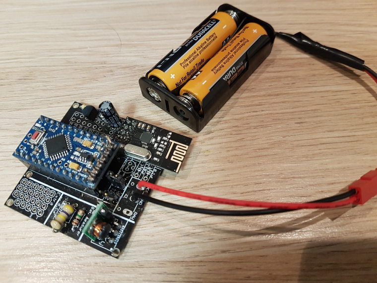
                                          I power it via 2AA battery. I did put a jumper on the battery point. And I am using a pro mini 3.3v (Cheap chinese clone). I am using a step up regulator to step it up to 3.3v for the arduino.

                                          I measured the voltages and they are as follow :

                                          Without USB programmer (Not working) :
                                          Battery : 3.00V
                                          Input step up : 3.00V
                                          Output Step UP : 3.35V
                                          VCC and GND on arduino : 3.34V
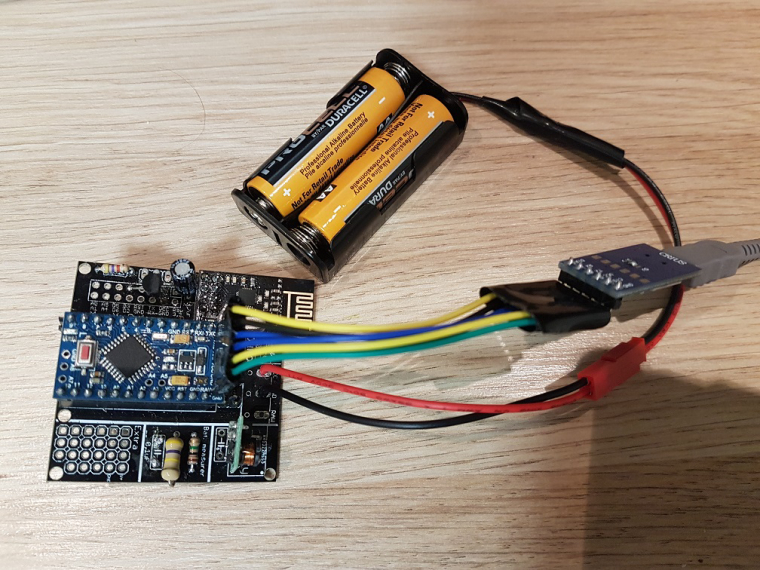
                                          VCC and GND on Radio : 3.01V

                                          With the USB programmer pluggued in (Working) :
                                          Battery : 3.00V
                                          Input step up : 3.00V
                                          Output Step UP : 3.47V
                                          VCC and GND on arduino : 3.48V
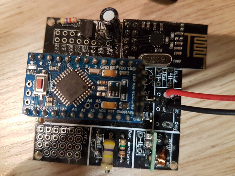
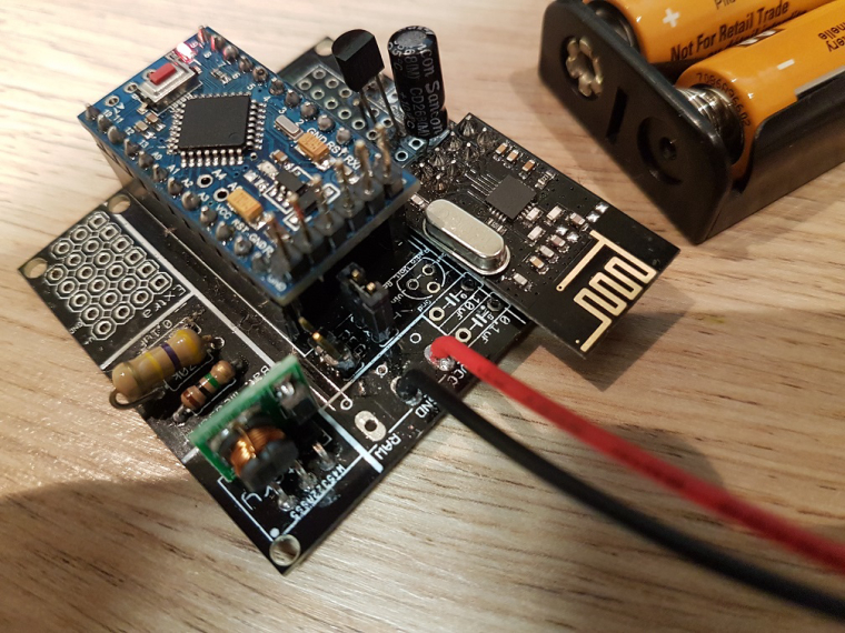
                                          VCC and GND on Radio : 3.00V

                                          Another information, I did not solder directly the arduino pro mini (you will see on the pictures). I don't know what the are called but I'll call them "extender". I use them so I can unplug the arduino in case I fried the pro mini.

                                          Here are some pictures with and without the usb programmer plugged in :

                                          3_1515614804192_20180110_145714.jpg

                                          2_1515614804191_20180110_145654.jpg

                                          1_1515614804191_20180110_145643.jpg

                                          0_1515614804191_20180110_145634.jpg

                                          sundberg84S gohanG 2 Replies Last reply
                                          1
                                          Reply
                                          • Reply as topic
                                          Log in to reply
                                          • Oldest to Newest
                                          • Newest to Oldest
                                          • Most Votes


                                          10

                                          Online

                                          11.7k

                                          Users

                                          11.2k

                                          Topics

                                          113.0k

                                          Posts


                                          Copyright 2019 TBD   |   Forum Guidelines   |   Privacy Policy   |   Terms of Service
                                          • Login

                                          • Don't have an account? Register

                                          • Login or register to search.
                                          • First post
                                            Last post
                                          0
                                          • MySensors
                                          • OpenHardware.io
                                          • Categories
                                          • Recent
                                          • Tags
                                          • Popular