Skip to content
  • OpenHardware.io
  • Categories
  • Recent
  • Tags
  • Popular
Skins
  • Light
  • Brite
  • Cerulean
  • Cosmo
  • Flatly
  • Journal
  • Litera
  • Lumen
  • Lux
  • Materia
  • Minty
  • Morph
  • Pulse
  • Sandstone
  • Simplex
  • Sketchy
  • Spacelab
  • United
  • Yeti
  • Zephyr
  • Dark
  • Cyborg
  • Darkly
  • Quartz
  • Slate
  • Solar
  • Superhero
  • Vapor

  • Default (No Skin)
  • No Skin
Collapse
Brand Logo
  1. Home
  2. OpenHardware.io
  3. 💬 Easy/Newbie PCB for MySensors
  • Getting Started
  • Controller
  • Build
  • Hardware
  • Download/API
  • Forum
  • Store

💬 Easy/Newbie PCB for MySensors

Scheduled Pinned Locked Moved OpenHardware.io
mysensorsbatteryeasynewbiepcbmysx
716 Posts 111 Posters 305.9k Views 93 Watching
  • Oldest to Newest
  • Newest to Oldest
  • Most Votes
Reply
  • Reply as topic
Log in to reply
This topic has been deleted. Only users with topic management privileges can see it.
  • sundberg84S sundberg84

    @BastienVH Good to hear - its not essential to have to 0.1uF cap on the voltage retulator, it will work without but its good to keep noice out.
    @ErrK Nice, I see you run through RAW pin and using the internal voltage regulator on the arduino - I have not tested that much, does it work ok?

    B Offline
    B Offline
    BastienVH
    wrote on last edited by
    #39

    @sundberg84
    When I get the caps, I'll place them on the board.
    I did notice alot of noise when I was reading battery state on a breadboard in an earlier build, so I will get that sorted.
    Only problem is I can't find them locally, so have to get them from China.
    Will take a while...

    1 Reply Last reply
    0
    • sundberg84S sundberg84

      @BastienVH Good to hear - its not essential to have to 0.1uF cap on the voltage retulator, it will work without but its good to keep noice out.
      @ErrK Nice, I see you run through RAW pin and using the internal voltage regulator on the arduino - I have not tested that much, does it work ok?

      ErrKE Offline
      ErrKE Offline
      ErrK
      Plugin Developer
      wrote on last edited by
      #40

      @sundberg84 yes it's working good. But the problem is that it's eating up the batteries :)
      It was up for only 15days.

      I will now test with a arduino that i have removed the led and volt regulator.

      1 Reply Last reply
      0
      • sundberg84S Offline
        sundberg84S Offline
        sundberg84
        Hardware Contributor
        wrote on last edited by
        #41

        Sounds good @ErrK - dont forget to power it through REG and not RAW on the PCB and add a jumper on REG since it wont work if you use the same setup as in the images and remove voltage regulator.

        Controller: Proxmox VM - Home Assistant
        MySensors GW: Arduino Uno - W5100 Ethernet, Gw Shield Nrf24l01+ 2,4Ghz
        MySensors GW: Arduino Uno - Gw Shield RFM69, 433mhz
        RFLink GW - Arduino Mega + RFLink Shield, 433mhz

        ErrKE 1 Reply Last reply
        0
        • sundberg84S sundberg84

          Sounds good @ErrK - dont forget to power it through REG and not RAW on the PCB and add a jumper on REG since it wont work if you use the same setup as in the images and remove voltage regulator.

          ErrKE Offline
          ErrKE Offline
          ErrK
          Plugin Developer
          wrote on last edited by
          #42

          Thank you @sundberg84. I will think of that.

          1 Reply Last reply
          0
          • BarnaB Offline
            BarnaB Offline
            Barna
            wrote on last edited by
            #43

            Hi,
            Why have you redesigned from rev7 to rev8?
            When will the rev8 be tested ?

            1 Reply Last reply
            0
            • sundberg84S Offline
              sundberg84S Offline
              sundberg84
              Hardware Contributor
              wrote on last edited by
              #44

              @Barna - I just wanted to make it smaller, with the radio not sticking out so much.
              I ordered them a while ago, so if they made it out of china before their new year I think it will be tested soon.

              Controller: Proxmox VM - Home Assistant
              MySensors GW: Arduino Uno - W5100 Ethernet, Gw Shield Nrf24l01+ 2,4Ghz
              MySensors GW: Arduino Uno - Gw Shield RFM69, 433mhz
              RFLink GW - Arduino Mega + RFLink Shield, 433mhz

              1 Reply Last reply
              0
              • dark-nicoD Offline
                dark-nicoD Offline
                dark-nico
                wrote on last edited by
                #45

                Just received Rev 8 :

                alt text

                I'll test it asap :smiley:

                1 Reply Last reply
                1
                • sundberg84S Offline
                  sundberg84S Offline
                  sundberg84
                  Hardware Contributor
                  wrote on last edited by sundberg84
                  #46

                  Nice. @dark-nico
                  The main concern is the new placement of caps and voltage divider - I hope they fit in between the radio and screw terminal. Should not be a problem - but you know, always nice to see it IRL. Might be good to solder them first before radio, arduino and screw terminal.

                  Controller: Proxmox VM - Home Assistant
                  MySensors GW: Arduino Uno - W5100 Ethernet, Gw Shield Nrf24l01+ 2,4Ghz
                  MySensors GW: Arduino Uno - Gw Shield RFM69, 433mhz
                  RFLink GW - Arduino Mega + RFLink Shield, 433mhz

                  1 Reply Last reply
                  0
                  • dark-nicoD Offline
                    dark-nicoD Offline
                    dark-nico
                    wrote on last edited by
                    #47

                    Ok, I'll do that.
                    My main problem is that I haven't received both my booster and my 5->3.3 reg. :disappointed:
                    So I can test Batt version by bypassing the booster, but it will not tell us if the reg placement is ok.
                    I'll dig in my "donor harware" if I can find a reg.

                    1 Reply Last reply
                    0
                    • dark-nicoD Offline
                      dark-nicoD Offline
                      dark-nico
                      wrote on last edited by
                      #48

                      Looks good!

                      alt text

                      and works fine!

                      Perfect, thanks again :thumbsup:

                      I'll test the batt version as soon as I receive the boosters.

                      1 Reply Last reply
                      0
                      • sundberg84S Offline
                        sundberg84S Offline
                        sundberg84
                        Hardware Contributor
                        wrote on last edited by sundberg84
                        #49

                        @dark-nico - You know its easy to cut the PCB to make it smaller? Using it as 5v you can remove the right battery part:

                        Either cut with a knife and brake:
                        https://www.youtube.com/watch?v=SiC-_g3iNb8

                        Or sometimes i just use a saw (before components are added) - might not be recommended ;)

                        Controller: Proxmox VM - Home Assistant
                        MySensors GW: Arduino Uno - W5100 Ethernet, Gw Shield Nrf24l01+ 2,4Ghz
                        MySensors GW: Arduino Uno - Gw Shield RFM69, 433mhz
                        RFLink GW - Arduino Mega + RFLink Shield, 433mhz

                        dark-nicoD 1 Reply Last reply
                        0
                        • sundberg84S sundberg84

                          @dark-nico - You know its easy to cut the PCB to make it smaller? Using it as 5v you can remove the right battery part:

                          Either cut with a knife and brake:
                          https://www.youtube.com/watch?v=SiC-_g3iNb8

                          Or sometimes i just use a saw (before components are added) - might not be recommended ;)

                          dark-nicoD Offline
                          dark-nicoD Offline
                          dark-nico
                          wrote on last edited by
                          #50

                          @sundberg84 - Yes I know that I can cut that part, but I think this one will be my test board with all this option, including the battery parts.
                          However I'll keep the video method in mind, I was thinking about using a dremel, but, it seems cleaner.

                          1 Reply Last reply
                          0
                          • sundberg84S Offline
                            sundberg84S Offline
                            sundberg84
                            Hardware Contributor
                            wrote on last edited by sundberg84
                            #51

                            @dark-nico Ok, have not tested adding both Bat and reg/5v posibilities at the same time. Might be that 5v travels backwards towards the booster... try it out, but as I said, not tested.

                            Controller: Proxmox VM - Home Assistant
                            MySensors GW: Arduino Uno - W5100 Ethernet, Gw Shield Nrf24l01+ 2,4Ghz
                            MySensors GW: Arduino Uno - Gw Shield RFM69, 433mhz
                            RFLink GW - Arduino Mega + RFLink Shield, 433mhz

                            1 Reply Last reply
                            0
                            • D Offline
                              D Offline
                              DutchMurk
                              wrote on last edited by
                              #52

                              @sundberg84 : I have also received the rev 7 from DirtyPCB and learned how to solder. Very nice and flexible design !
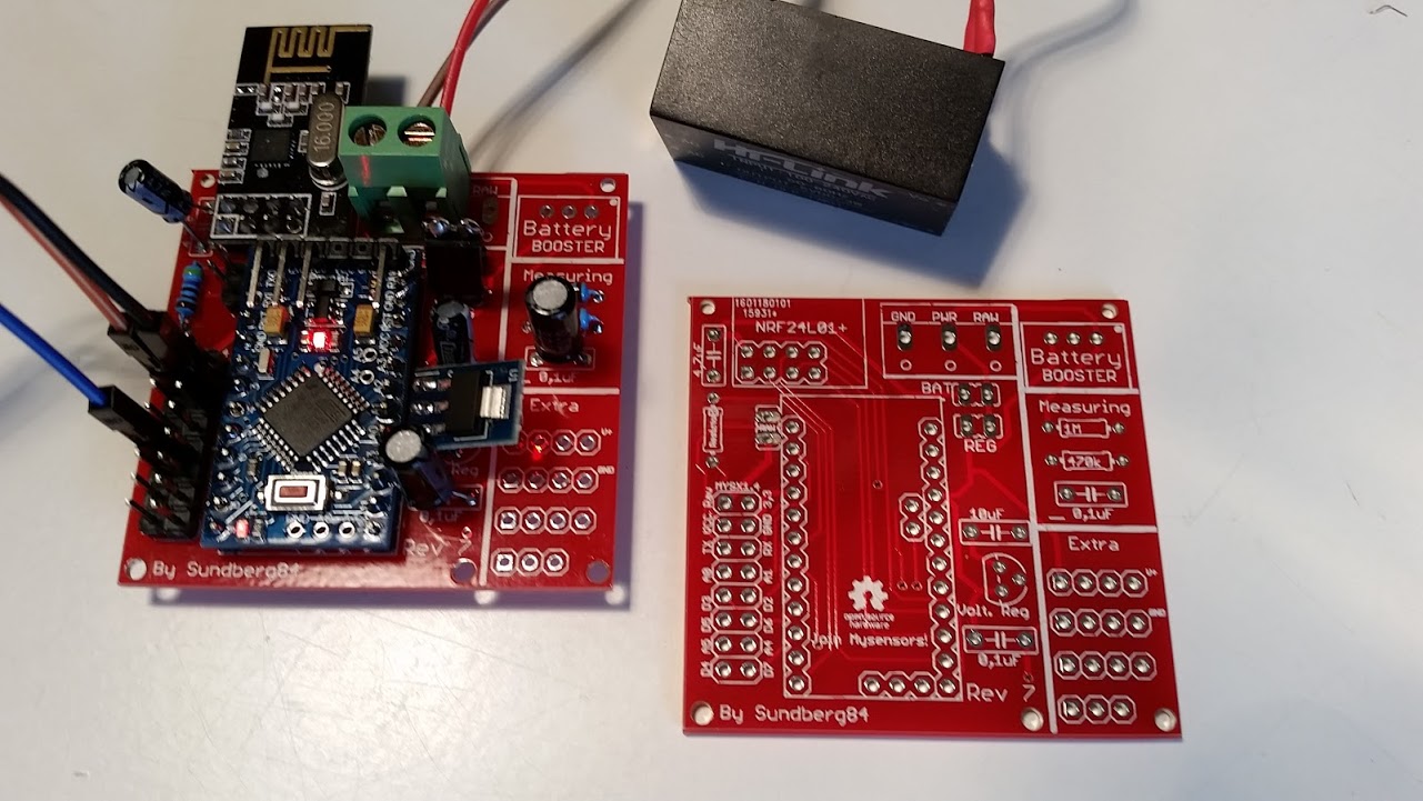
                              0_1455455160676_20160214_133450.jpg
                              Perfect for a Newbie :). Thnaks a lot for sharing

                              1 Reply Last reply
                              0
                              • sundberg84S Offline
                                sundberg84S Offline
                                sundberg84
                                Hardware Contributor
                                wrote on last edited by sundberg84
                                #53

                                Hi!
                                No problems! Makes me glad to see i made something usefull for others :)
                                Interesting setup you got the with the HLK as power :+1:

                                Controller: Proxmox VM - Home Assistant
                                MySensors GW: Arduino Uno - W5100 Ethernet, Gw Shield Nrf24l01+ 2,4Ghz
                                MySensors GW: Arduino Uno - Gw Shield RFM69, 433mhz
                                RFLink GW - Arduino Mega + RFLink Shield, 433mhz

                                1 Reply Last reply
                                0
                                • D Offline
                                  D Offline
                                  dakipro
                                  wrote on last edited by
                                  #54

                                  Great design and project, thank you for sharing it. I really like the rev8 approach in reducing overall size as it will fitt much better in my boxes.
                                  Is it possible to get rev8 files needed to order PCBs from some other places?
                                  Keep up the good work!

                                  C: OpenHAB2 with node-red on linux laptop
                                  GW: Arduino Nano - W5100 Ethernet, Nrf24l01+ 2,4Ghz mqtt
                                  GW: Arduino Mega, RFLink 433Mhz

                                  1 Reply Last reply
                                  0
                                  • sundberg84S Offline
                                    sundberg84S Offline
                                    sundberg84
                                    Hardware Contributor
                                    wrote on last edited by
                                    #55

                                    @dakipro If you "download all project files" @ https://www.openhardware.io/you will get all files (Eagles, Gerber (run with Iteads CAM job) and other stuff).

                                    Controller: Proxmox VM - Home Assistant
                                    MySensors GW: Arduino Uno - W5100 Ethernet, Gw Shield Nrf24l01+ 2,4Ghz
                                    MySensors GW: Arduino Uno - Gw Shield RFM69, 433mhz
                                    RFLink GW - Arduino Mega + RFLink Shield, 433mhz

                                    1 Reply Last reply
                                    0
                                    • C Offline
                                      C Offline
                                      chuckconnors
                                      wrote on last edited by
                                      #56

                                      Please excuse the questions, but you did say this is for Newbies, right? :)

                                      I'm planning on using this with the 3.3v Arduino with battery power once things are debugged. I see above that you say to power from the battery input rather than the FTDI pins. Is that for 5V and 3.3V? Also, what is the resistor labeled D3 Res Temp/Hum used for?

                                      1 Reply Last reply
                                      0
                                      • sundberg84S Offline
                                        sundberg84S Offline
                                        sundberg84
                                        Hardware Contributor
                                        wrote on last edited by sundberg84
                                        #57

                                        Hi! @chuckconnors

                                        You should input power/gnd to the 5v/GND on the PCB and not the ftdi connector on the arduino you have soldered on the pcb. See the images above. This is how the board is designed. It doesnt matter if its 3.3 or 5v.
                                        The resistor is for if you want to use for example a dallas temp or dht22 on pin 3, then you can add a resistor there since these sensors require this.

                                        Controller: Proxmox VM - Home Assistant
                                        MySensors GW: Arduino Uno - W5100 Ethernet, Gw Shield Nrf24l01+ 2,4Ghz
                                        MySensors GW: Arduino Uno - Gw Shield RFM69, 433mhz
                                        RFLink GW - Arduino Mega + RFLink Shield, 433mhz

                                        C 1 Reply Last reply
                                        0
                                        • sundberg84S sundberg84

                                          Hi! @chuckconnors

                                          You should input power/gnd to the 5v/GND on the PCB and not the ftdi connector on the arduino you have soldered on the pcb. See the images above. This is how the board is designed. It doesnt matter if its 3.3 or 5v.
                                          The resistor is for if you want to use for example a dallas temp or dht22 on pin 3, then you can add a resistor there since these sensors require this.

                                          C Offline
                                          C Offline
                                          chuckconnors
                                          wrote on last edited by
                                          #58

                                          @sundberg84 Thanks for the reply. Please forgive my ignorance, but can you explain what happens if you connect power via the FTDI pins? Wouldn't it still power the chip and radio?

                                          Should I supply the 5V/GND from the FTDI interface to the VCC/GND pads on the bottom left side of the board?

                                          1 Reply Last reply
                                          0
                                          Reply
                                          • Reply as topic
                                          Log in to reply
                                          • Oldest to Newest
                                          • Newest to Oldest
                                          • Most Votes


                                          18

                                          Online

                                          11.7k

                                          Users

                                          11.2k

                                          Topics

                                          113.0k

                                          Posts


                                          Copyright 2019 TBD   |   Forum Guidelines   |   Privacy Policy   |   Terms of Service
                                          • Login

                                          • Don't have an account? Register

                                          • Login or register to search.
                                          • First post
                                            Last post
                                          0
                                          • OpenHardware.io
                                          • Categories
                                          • Recent
                                          • Tags
                                          • Popular