💬 Easy/Newbie PCB for MySensors
-
@anticimex - thanks for input. Same with radio I guess... ? Don't know how to solve it by fitting all these things into one board.
@sundberg84 The rfm69 radio can be surface mounted. If one goes for headers, the pitch it uses allow for low profile headers so the radio should go clear under a daughterboard assuming it does not have reverse side mounted components with a high profile.
Do you feel secure today? No? Start requiring some signatures and feel better tomorrow ;)
-
@sundberg84 The rfm69 radio can be surface mounted. If one goes for headers, the pitch it uses allow for low profile headers so the radio should go clear under a daughterboard assuming it does not have reverse side mounted components with a high profile.
@anticimex you could use male headers on mother and female headers on daughter...
Or just mount the mother on top.
here it seems the capacitor is the biggest concern.
Controller: Proxmox VM - Home Assistant
MySensors GW: Arduino Uno - W5100 Ethernet, Gw Shield Nrf24l01+ 2,4Ghz
MySensors GW: Arduino Uno - Gw Shield RFM69, 433mhz
RFLink GW - Arduino Mega + RFLink Shield, 433mhz -
@anticimex you could use male headers on mother and female headers on daughter...
Or just mount the mother on top.
here it seems the capacitor is the biggest concern.
@sundberg84 if I remember correctly, the motherboard has to use male MYSX. So there is no option for that. I thought you planned to use sockets for the arduino. But if it is soldered directly on the pcb, it should go clear I think. But best to use angled ftdi interface then.
-
Yes I guess the only viable solution with MYSX and a pro mini is to solder the promini without headers so it can be under the daughter board and big (electrolytic capacitor) or sensible (radio antenna) stuff can be as far away as possible.
@sundberg84, I'm not sure it's great to have antenna in that position for my "vertical" concept but I guess it's not a great idea any more to do that. Now that pin 1 is in a corner I have all the space in the world to put reed/hall switch next to the other side (on top of pro mini) and it will be much more in line with expected use of MYSX connector.
Antenna is on the side that's not supposed to be below daughter board so I don't think you can do better for that., I think it's much better than before, I'll be able to make a board that's more versatile than the current one with footprints for most common sensors. -
@sundberg84
not sure but on your preview, I see that you don't use any gnd planes?? Imho, just sayin for your users :), it would be better to have it, ideally unbroken+ vias, for impedance, emi, rf counterpoise, impedance matching rf feedline to sma depending on its length and how it's routed etc.., maybe a little google it ;)looks nice :+1:
-
@sundberg84
not sure but on your preview, I see that you don't use any gnd planes?? Imho, just sayin for your users :), it would be better to have it, ideally unbroken+ vias, for impedance, emi, rf counterpoise, impedance matching rf feedline to sma depending on its length and how it's routed etc.., maybe a little google it ;)looks nice :+1:
@scalz - yes it is true about ground plane! I did that one rev 4 or something but something broke the thing... so I have been hesitating since but I know all about the benefits - been reading and googling.
I have not made any traces or planes on the images - just component placement. I will give it another shot... maybe I have learned some since rev 4 ;)
Thanks for your feedback.
Controller: Proxmox VM - Home Assistant
MySensors GW: Arduino Uno - W5100 Ethernet, Gw Shield Nrf24l01+ 2,4Ghz
MySensors GW: Arduino Uno - Gw Shield RFM69, 433mhz
RFLink GW - Arduino Mega + RFLink Shield, 433mhz -
@scalz - yes it is true about ground plane! I did that one rev 4 or something but something broke the thing... so I have been hesitating since but I know all about the benefits - been reading and googling.
I have not made any traces or planes on the images - just component placement. I will give it another shot... maybe I have learned some since rev 4 ;)
Thanks for your feedback.
@sundberg84 I forgot to mention that your nRF24 module goes very close to the MYSX. There is a risk a female receptacle might collide with the rf module if you are unlucky. And daughterboards will most likely be at least as wide as the courtyard of the MYSX.
-
@sundberg84
yes not talking about your latest but saw that on your rev9 and 10 pics.
it will make it better, and it's good point for rf quality (range and msg fail) ;)
placing planes is one of the first thing I usually do after component placements.. then it's easier to route as it solves many connection.keep the good work!
-
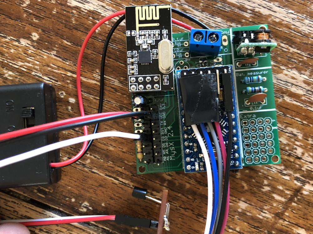
@sundberg84 I have a "newby" question about how to use the Extra's part of the board. If I want to connect a DS18B20 sensor per example can I just solder it on the extra area and connect is with some wires to the pinout I need?
Asking this because I did this with the i2c sensor on the board discussed here. having a wire form the extras towards the arduino i2c pins directly. Later I discovered that the i2c pins are also on the board.
So how to deal with this? -
you can add a wire to the I2C pins, in your case you just need a short wire to a digital pin that are just next to the Extra area
@gohan said in 💬 Easy/Newbie PCB for MySensors:
you can add a wire to the I2C pins, in your case you just need a short wire to a digital pin that are just next to the Extra area
Ok. And if attaching a DS18B20 I have a pull up resistor soldered on the board. Than it is also just the digital pin I need from the board? D3 I think?
-
@gohan said in 💬 Easy/Newbie PCB for MySensors:
you can add a wire to the I2C pins, in your case you just need a short wire to a digital pin that are just next to the Extra area
Ok. And if attaching a DS18B20 I have a pull up resistor soldered on the board. Than it is also just the digital pin I need from the board? D3 I think?
@mr_sensor with a DS18B20 temp sensor I just solder it to the MysX pins (D3, Gnd and VCC) directly and populate the resistor for D3.
-
@mr_sensor with a DS18B20 temp sensor I just solder it to the MysX pins (D3, Gnd and VCC) directly and populate the resistor for D3.
@sundberg84 Yes thanks I did so. But do not get any temp read out? Have al in space also the 4,7 k resistor.
this is my sketch:
[code]


/**
 * The MySensors Arduino library handles the wireless radio link and protocol
 * between your home built sensors/actuators and HA controller of choice.
 * The sensors forms a self healing radio network with optional repeaters. Each
 * repeater and gateway builds a routing tables in EEPROM which keeps track of the
 * network topology allowing messages to be routed to nodes.
 *
 * Created by Henrik Ekblad <henrik.ekblad@mysensors.org>
 * Copyright (C) 2013-2015 Sensnology AB
 * Full contributor list: https://github.com/mysensors/Arduino/graphs/contributors
 *
 * Documentation: http://www.mysensors.org
 * Support Forum: http://forum.mysensors.org
 *
 * This program is free software; you can redistribute it and/or
 * modify it under the terms of the GNU General Public License
 * version 2 as published by the Free Software Foundation.
 *
 *******************************
 *
 * REVISION HISTORY
 * Version 1.0: Henrik EKblad
 * Version 1.1 - 2016-07-20: Converted to MySensors v2.0 and added various improvements - Torben Woltjen (mozzbozz)
 *
 * DESCRIPTION
 * This sketch provides an example of how to implement a humidity/temperature
 *
 * Dallas temperature sensor DS18B20
 *
 * For more information, please visit:
 * http://www.mysensors.org/build/humidity
 *
 HTU21D Humidity Sensor
 Hardware Connections (Breakoutboard to Arduino):
 -VCC = 3.3V
 -GND = GND
 -data  = D3 met pcb 470 uf resistor
 */


#define MY_NODE_ID 4
#define MY_PARENT_NODE_ID 0
#define MY_PARENT_NODE_IS_STATIC

// Enable debug prints
#define MY_DEBUG

// Enable and select radio type attached
#define MY_RADIO_NRF24
//#define MY_RADIO_RFM69
//#define MY_RS485

#include <MySensors.h>
#include <OneWire.h>
//#include <Wire.h>
#include <SPI.h>
#include <DallasTemperature.h>

// Force sending an update of the temperature after n sensor reads, so a controller showing the
// timestamp of the last update doesn't show something like 3 hours in the unlikely case, that
// the value didn't change since;
// i.e. the sensor would force sending an update every UPDATE_INTERVAL*FORCE_UPDATE_N_READS [ms]
//static const uint8_t FORCE_UPDATE_N_READS = 10;

#define COMPARE_TEMP 1 // Send temperature only if changed? 1 = Yes 0 = No

#define ONE_WIRE_BUS 3 // Pin where dallase sensor is connected
#define MAX_ATTACHED_DS18B20 16
//unsigned long SLEEP_TIME = 30000; // Sleep time between reads (in milliseconds)
OneWire oneWire(ONE_WIRE_BUS); // Setup a oneWire instance to communicate with any OneWire devices (not just Maxim/Dallas temperature ICs)
DallasTemperature sensors(&oneWire); // Pass the oneWire reference to Dallas Temperature.
float lastTemperature[MAX_ATTACHED_DS18B20];
int numSensors=0;
bool receivedConfig = false;
bool metric = true;

#define CHILD_ID_TEMP 0
#define CHILD_ID_BATTERY 1
#define CHILD_ID_VOLT 2
//#define CHILD_ID_PRCNT 3

//float lastTemp;
//float lastHum;

//uint8_t nNoUpdatesTemp;
//uint8_t nNoUpdatesHum;
//boolean metric = true;


void presentation()
{
 // Send the Sketch Version Information to the Gateway
  sendSketchInfo("Temperature Sensor", "1.1");

 // Register all sensors to gw (they will be created as child devices)
//  present(CHILD_ID_HUM, S_HUM);
  present(CHILD_ID_TEMP, S_TEMP);
   present(CHILD_ID_BATTERY, S_MULTIMETER);
  //metric = getControllerConfig().isMetric;

// Fetch the number of attached temperature sensors
  numSensors = sensors.getDeviceCount();

  // Present all sensors to controller
  for (int i=0; i<numSensors && i<MAX_ATTACHED_DS18B20; i++) {
     present(i, S_TEMP);
  }

}

int BATTERY_SENSE_PIN = A0;  // select the input pin for the battery sense point

unsigned long SLEEP_TIME = 60000; // Sleep time between reads (in milliseconds)  60000
static int oldBatteryPcnt = 0;


//Create an instance of the object

  MyMessage msg(0,V_TEMP);
//MyMessage msgHum(CHILD_ID_HUM, V_HUM);
MyMessage msgTemp(CHILD_ID_TEMP, V_TEMP);
MyMessage msgBattery(CHILD_ID_BATTERY, V_VOLTAGE);
//MyMessage msgBattery(CHILD_ID_BATTERY, V_PRC);


void setup() {
    // Startup up the OneWire library
  sensors.begin();

     // use the 1.1 V internal reference
#if defined(__AVR_ATmega2560__)
    analogReference(INTERNAL1V1);
#else
    analogReference(INTERNAL);
#endif

// requestTemperatures() will not block current thread
  sensors.setWaitForConversion(false);

}

void loop()
{


// Fetch temperatures from Dallas sensors
  sensors.requestTemperatures();

  // query conversion time and sleep until conversion completed
  int16_t conversionTime = sensors.millisToWaitForConversion(sensors.getResolution());
  // sleep() call can be replaced by wait() call if node need to process incoming messages (or if node is repeater)
  sleep(conversionTime);

  // Read temperatures and send them to controller
  for (int i=0; i<numSensors && i<MAX_ATTACHED_DS18B20; i++) {

    // Fetch and round temperature to one decimal
    float temperature = static_cast<float>(static_cast<int>((getControllerConfig().isMetric?sensors.getTempCByIndex(i):sensors.getTempFByIndex(i)) * 10.)) / 10.;

    // Only send data if temperature has changed and no error
    #if COMPARE_TEMP == 1
    if (lastTemperature[i] != temperature && temperature != -127.00 && temperature != 85.00) {
    #else
    if (temperature != -127.00 && temperature != 85.00) {
    #endif

      // Send in the new temperature
      send(msg.setSensor(i).set(temperature,1));
      // Save new temperatures for next compare
      lastTemperature[i]=temperature;
    }
  }


// some delay here
   delay(500);

   // get the battery Voltage

    int sensorValue = analogRead(BATTERY_SENSE_PIN);
    delay(500);
#ifdef MY_DEBUG
    Serial.println(sensorValue);
#endif

    // 1M, 470K divider across battery and using internal ADC ref of 1.1V
    // Sense point is bypassed with 0.1 uF cap to reduce noise at that point
    // ((1e6+470e3)/470e3)*1.1 = Vmax = 3.44 Volts
    // 3.44/1023 = Volts per bit = 0.003363075
    int batteryPcnt = sensorValue / 10;

#ifdef MY_DEBUG
    float batteryV  = sensorValue * 0.003363075;
    Serial.print("Child ID ");
    Serial.print(CHILD_ID_BATTERY);
    Serial.print("Battery Voltage: ");
    Serial.print(batteryV);
    Serial.println(" V");

    Serial.print("Battery Percent: ");
    Serial.print(batteryPcnt);
    Serial.println(" %");
#endif

    if (oldBatteryPcnt != batteryPcnt) {
        // Power up radio after sleep

        sendBatteryLevel(batteryPcnt);
        oldBatteryPcnt = batteryPcnt;
    }

  sleep(SLEEP_TIME); //sleep a bit

}
[/code]```
| / |_ / | ___ _ __ ___ ___ _ __ ___
| |/| | | | _ \ / _ \_ \/ __|/ _ \|_/ __|
| | | | || || | / | | _ \ _ | | \�
|| ||_, |/ ___|| ||/_/|| |/
|__/ 2.2.016 MCO:BGN:INIT NODE,CP=RNNNA---,VER=2.2.0
26 TSM:INIT
28 TSF:WUR:MS=0
34 TSM:INIT:TSP OK
36 TSM:INIT:STATID=4
38 TSF:SID:OK,ID=4
40 TSM:FPAR
43 TSM:FPAR:STATP=0
45 TSM:ID
47 TSM:ID:OK
47 TSM:UPL
53 TSF:MSG:SEND,4-4-0-0,s=255,c=3,t=24,pt=1,l=1,sg=0,ft=0,st=OK:1
67 TSF:MSG:READ,0-0-4,s=255,c=3,t=25,pt=1,l=1,sg=0:1
71 TSF:MSG:PONG RECV,HP=1
75 TSM:UPL:OK
77 TSM:READY:ID=4,PAR=0,DIS=1
116 !TSF:MSG:SEND,4-4-0-0,s=255,c=3,t=15,pt=6,l=2,sg=0,ft=0,st=NACK:0100
2125 TSF:MSG:SEND,4-4-0-0,s=255,c=0,t=17,pt=0,l=5,sg=0,ft=1,st=OK:2.2.0
2138 TSF:MSG:SEND,4-4-0-0,s=255,c=3,t=6,pt=1,l=1,sg=0,ft=0,st=OK:0
4177 TSF:MSG:SEND,4-4-0-0,s=255,c=3,t=11,pt=0,l=18,sg=0,ft=0,st=OK:Temperature Sensor
4196 TSF:MSG:SEND,4-4-0-0,s=255,c=3,t=12,pt=0,l=3,sg=0,ft=0,st=OK:1.1
4214 TSF:MSG:SEND,4-4-0-0,s=0,c=0,t=6,pt=0,l=0,sg=0,ft=0,st=OK:
4227 TSF:MSG:SEND,4-4-0-0,s=1,c=0,t=30,pt=0,l=0,sg=0,ft=0,st=OK:
4235 MCO:REG:REQ
4237 TSF:MSG:SEND,4-4-0-0,s=255,c=3,t=26,pt=1,l=1,sg=0,ft=0,st=OK:2
6246 TSF:MSG:SEND,4-4-0-0,s=255,c=3,t=26,pt=1,l=1,sg=0,ft=0,st=OK:2
8255 TSF:MSG:SEND,4-4-0-0,s=255,c=3,t=26,pt=1,l=1,sg=0,ft=0,st=OK:2
10264 TSF:MSG:SEND,4-4-0-0,s=255,c=3,t=26,pt=1,l=1,sg=0,ft=0,st=OK:2
12273 MCO:BGN:STP
12275 MCO:BGN:INIT OK,TSP=1
12279 MCO:SLP:MS=94,SMS=0,I1=255,M1=255,I2=255,M2=255
12285 TSF:TDI:TSL
12288 MCO:SLP:WUP=-1
12290 TSF:TRI:TSB
915
Child ID 1Battery Voltage: 3.08 V
Battery Percent: 91 %
13297 TSF:MSG:SEND,4-4-0-0,s=255,c=3,t=0,pt=1,l=1,sg=0,ft=0,st=OK:91
13305 MCO:SLP:MS=60000,SMS=0,I1=255,M1=255,I2=255,M2=255
13312 TSF:TDI:TSL
13314 MCO:SLP:WUP=-1
13316 TSF:TRI:TSB
13320 MCO:SLP:MS=94,SMS=0,I1=255,M1=255,I2=255,M2=255
13326 TSF:TDI:TSL
13328 MCO:SLP:WUP=-1
13330 TSF:TRI:TSB
826
Child ID 1Battery Voltage: 2.78 V
Battery Percent: 82 %
14340 TSF:MSG:SEND,4-4-0-0,s=255,c=3,t=0,pt=1,l=1,sg=0,ft=0,st=OK:82
14346 MCO:SLP:MS=60000,SMS=0,I1=255,M1=255,I2=255,M2=255
14352 TSF:TDI:TSL -
@sundberg84 Yes thanks I did so. But do not get any temp read out? Have al in space also the 4,7 k resistor.
this is my sketch:
[code]


/**
 * The MySensors Arduino library handles the wireless radio link and protocol
 * between your home built sensors/actuators and HA controller of choice.
 * The sensors forms a self healing radio network with optional repeaters. Each
 * repeater and gateway builds a routing tables in EEPROM which keeps track of the
 * network topology allowing messages to be routed to nodes.
 *
 * Created by Henrik Ekblad <henrik.ekblad@mysensors.org>
 * Copyright (C) 2013-2015 Sensnology AB
 * Full contributor list: https://github.com/mysensors/Arduino/graphs/contributors
 *
 * Documentation: http://www.mysensors.org
 * Support Forum: http://forum.mysensors.org
 *
 * This program is free software; you can redistribute it and/or
 * modify it under the terms of the GNU General Public License
 * version 2 as published by the Free Software Foundation.
 *
 *******************************
 *
 * REVISION HISTORY
 * Version 1.0: Henrik EKblad
 * Version 1.1 - 2016-07-20: Converted to MySensors v2.0 and added various improvements - Torben Woltjen (mozzbozz)
 *
 * DESCRIPTION
 * This sketch provides an example of how to implement a humidity/temperature
 *
 * Dallas temperature sensor DS18B20
 *
 * For more information, please visit:
 * http://www.mysensors.org/build/humidity
 *
 HTU21D Humidity Sensor
 Hardware Connections (Breakoutboard to Arduino):
 -VCC = 3.3V
 -GND = GND
 -data  = D3 met pcb 470 uf resistor
 */


#define MY_NODE_ID 4
#define MY_PARENT_NODE_ID 0
#define MY_PARENT_NODE_IS_STATIC

// Enable debug prints
#define MY_DEBUG

// Enable and select radio type attached
#define MY_RADIO_NRF24
//#define MY_RADIO_RFM69
//#define MY_RS485

#include <MySensors.h>
#include <OneWire.h>
//#include <Wire.h>
#include <SPI.h>
#include <DallasTemperature.h>

// Force sending an update of the temperature after n sensor reads, so a controller showing the
// timestamp of the last update doesn't show something like 3 hours in the unlikely case, that
// the value didn't change since;
// i.e. the sensor would force sending an update every UPDATE_INTERVAL*FORCE_UPDATE_N_READS [ms]
//static const uint8_t FORCE_UPDATE_N_READS = 10;

#define COMPARE_TEMP 1 // Send temperature only if changed? 1 = Yes 0 = No

#define ONE_WIRE_BUS 3 // Pin where dallase sensor is connected
#define MAX_ATTACHED_DS18B20 16
//unsigned long SLEEP_TIME = 30000; // Sleep time between reads (in milliseconds)
OneWire oneWire(ONE_WIRE_BUS); // Setup a oneWire instance to communicate with any OneWire devices (not just Maxim/Dallas temperature ICs)
DallasTemperature sensors(&oneWire); // Pass the oneWire reference to Dallas Temperature.
float lastTemperature[MAX_ATTACHED_DS18B20];
int numSensors=0;
bool receivedConfig = false;
bool metric = true;

#define CHILD_ID_TEMP 0
#define CHILD_ID_BATTERY 1
#define CHILD_ID_VOLT 2
//#define CHILD_ID_PRCNT 3

//float lastTemp;
//float lastHum;

//uint8_t nNoUpdatesTemp;
//uint8_t nNoUpdatesHum;
//boolean metric = true;


void presentation()
{
 // Send the Sketch Version Information to the Gateway
  sendSketchInfo("Temperature Sensor", "1.1");

 // Register all sensors to gw (they will be created as child devices)
//  present(CHILD_ID_HUM, S_HUM);
  present(CHILD_ID_TEMP, S_TEMP);
   present(CHILD_ID_BATTERY, S_MULTIMETER);
  //metric = getControllerConfig().isMetric;

// Fetch the number of attached temperature sensors
  numSensors = sensors.getDeviceCount();

  // Present all sensors to controller
  for (int i=0; i<numSensors && i<MAX_ATTACHED_DS18B20; i++) {
     present(i, S_TEMP);
  }

}

int BATTERY_SENSE_PIN = A0;  // select the input pin for the battery sense point

unsigned long SLEEP_TIME = 60000; // Sleep time between reads (in milliseconds)  60000
static int oldBatteryPcnt = 0;


//Create an instance of the object

  MyMessage msg(0,V_TEMP);
//MyMessage msgHum(CHILD_ID_HUM, V_HUM);
MyMessage msgTemp(CHILD_ID_TEMP, V_TEMP);
MyMessage msgBattery(CHILD_ID_BATTERY, V_VOLTAGE);
//MyMessage msgBattery(CHILD_ID_BATTERY, V_PRC);


void setup() {
    // Startup up the OneWire library
  sensors.begin();

     // use the 1.1 V internal reference
#if defined(__AVR_ATmega2560__)
    analogReference(INTERNAL1V1);
#else
    analogReference(INTERNAL);
#endif

// requestTemperatures() will not block current thread
  sensors.setWaitForConversion(false);

}

void loop()
{


// Fetch temperatures from Dallas sensors
  sensors.requestTemperatures();

  // query conversion time and sleep until conversion completed
  int16_t conversionTime = sensors.millisToWaitForConversion(sensors.getResolution());
  // sleep() call can be replaced by wait() call if node need to process incoming messages (or if node is repeater)
  sleep(conversionTime);

  // Read temperatures and send them to controller
  for (int i=0; i<numSensors && i<MAX_ATTACHED_DS18B20; i++) {

    // Fetch and round temperature to one decimal
    float temperature = static_cast<float>(static_cast<int>((getControllerConfig().isMetric?sensors.getTempCByIndex(i):sensors.getTempFByIndex(i)) * 10.)) / 10.;

    // Only send data if temperature has changed and no error
    #if COMPARE_TEMP == 1
    if (lastTemperature[i] != temperature && temperature != -127.00 && temperature != 85.00) {
    #else
    if (temperature != -127.00 && temperature != 85.00) {
    #endif

      // Send in the new temperature
      send(msg.setSensor(i).set(temperature,1));
      // Save new temperatures for next compare
      lastTemperature[i]=temperature;
    }
  }


// some delay here
   delay(500);

   // get the battery Voltage

    int sensorValue = analogRead(BATTERY_SENSE_PIN);
    delay(500);
#ifdef MY_DEBUG
    Serial.println(sensorValue);
#endif

    // 1M, 470K divider across battery and using internal ADC ref of 1.1V
    // Sense point is bypassed with 0.1 uF cap to reduce noise at that point
    // ((1e6+470e3)/470e3)*1.1 = Vmax = 3.44 Volts
    // 3.44/1023 = Volts per bit = 0.003363075
    int batteryPcnt = sensorValue / 10;

#ifdef MY_DEBUG
    float batteryV  = sensorValue * 0.003363075;
    Serial.print("Child ID ");
    Serial.print(CHILD_ID_BATTERY);
    Serial.print("Battery Voltage: ");
    Serial.print(batteryV);
    Serial.println(" V");

    Serial.print("Battery Percent: ");
    Serial.print(batteryPcnt);
    Serial.println(" %");
#endif

    if (oldBatteryPcnt != batteryPcnt) {
        // Power up radio after sleep

        sendBatteryLevel(batteryPcnt);
        oldBatteryPcnt = batteryPcnt;
    }

  sleep(SLEEP_TIME); //sleep a bit

}
[/code]```
| / |_ / | ___ _ __ ___ ___ _ __ ___
| |/| | | | _ \ / _ \_ \/ __|/ _ \|_/ __|
| | | | || || | / | | _ \ _ | | \�
|| ||_, |/ ___|| ||/_/|| |/
|__/ 2.2.016 MCO:BGN:INIT NODE,CP=RNNNA---,VER=2.2.0
26 TSM:INIT
28 TSF:WUR:MS=0
34 TSM:INIT:TSP OK
36 TSM:INIT:STATID=4
38 TSF:SID:OK,ID=4
40 TSM:FPAR
43 TSM:FPAR:STATP=0
45 TSM:ID
47 TSM:ID:OK
47 TSM:UPL
53 TSF:MSG:SEND,4-4-0-0,s=255,c=3,t=24,pt=1,l=1,sg=0,ft=0,st=OK:1
67 TSF:MSG:READ,0-0-4,s=255,c=3,t=25,pt=1,l=1,sg=0:1
71 TSF:MSG:PONG RECV,HP=1
75 TSM:UPL:OK
77 TSM:READY:ID=4,PAR=0,DIS=1
116 !TSF:MSG:SEND,4-4-0-0,s=255,c=3,t=15,pt=6,l=2,sg=0,ft=0,st=NACK:0100
2125 TSF:MSG:SEND,4-4-0-0,s=255,c=0,t=17,pt=0,l=5,sg=0,ft=1,st=OK:2.2.0
2138 TSF:MSG:SEND,4-4-0-0,s=255,c=3,t=6,pt=1,l=1,sg=0,ft=0,st=OK:0
4177 TSF:MSG:SEND,4-4-0-0,s=255,c=3,t=11,pt=0,l=18,sg=0,ft=0,st=OK:Temperature Sensor
4196 TSF:MSG:SEND,4-4-0-0,s=255,c=3,t=12,pt=0,l=3,sg=0,ft=0,st=OK:1.1
4214 TSF:MSG:SEND,4-4-0-0,s=0,c=0,t=6,pt=0,l=0,sg=0,ft=0,st=OK:
4227 TSF:MSG:SEND,4-4-0-0,s=1,c=0,t=30,pt=0,l=0,sg=0,ft=0,st=OK:
4235 MCO:REG:REQ
4237 TSF:MSG:SEND,4-4-0-0,s=255,c=3,t=26,pt=1,l=1,sg=0,ft=0,st=OK:2
6246 TSF:MSG:SEND,4-4-0-0,s=255,c=3,t=26,pt=1,l=1,sg=0,ft=0,st=OK:2
8255 TSF:MSG:SEND,4-4-0-0,s=255,c=3,t=26,pt=1,l=1,sg=0,ft=0,st=OK:2
10264 TSF:MSG:SEND,4-4-0-0,s=255,c=3,t=26,pt=1,l=1,sg=0,ft=0,st=OK:2
12273 MCO:BGN:STP
12275 MCO:BGN:INIT OK,TSP=1
12279 MCO:SLP:MS=94,SMS=0,I1=255,M1=255,I2=255,M2=255
12285 TSF:TDI:TSL
12288 MCO:SLP:WUP=-1
12290 TSF:TRI:TSB
915
Child ID 1Battery Voltage: 3.08 V
Battery Percent: 91 %
13297 TSF:MSG:SEND,4-4-0-0,s=255,c=3,t=0,pt=1,l=1,sg=0,ft=0,st=OK:91
13305 MCO:SLP:MS=60000,SMS=0,I1=255,M1=255,I2=255,M2=255
13312 TSF:TDI:TSL
13314 MCO:SLP:WUP=-1
13316 TSF:TRI:TSB
13320 MCO:SLP:MS=94,SMS=0,I1=255,M1=255,I2=255,M2=255
13326 TSF:TDI:TSL
13328 MCO:SLP:WUP=-1
13330 TSF:TRI:TSB
826
Child ID 1Battery Voltage: 2.78 V
Battery Percent: 82 %
14340 TSF:MSG:SEND,4-4-0-0,s=255,c=3,t=0,pt=1,l=1,sg=0,ft=0,st=OK:82
14346 MCO:SLP:MS=60000,SMS=0,I1=255,M1=255,I2=255,M2=255
14352 TSF:TDI:TSL@mr_sensor - it looks ok except the temp sensor. Hard to say but doulecheck your wiring!
-
@mr_sensor - it looks ok except the temp sensor. Hard to say but doulecheck your wiring!
-
@mr_sensor looks right. Upload a sketch without MySensors from the temp library
-
@mr_sensor looks right. Upload a sketch without MySensors from the temp library
@sundberg84 I run the "single" sketch from temp library and this is what I get:
Dallas Temperature IC Control Library Demo Locating devices...Found 0 devices. Parasite power is: OFF Unable to find address for Device 0 Device 0 Address: 0000000000000000 Device 0 Resolution: 0 Requesting temperatures...DONE Temp C: -127.00 Temp F: -196.60 Requesting temperatures...DONE Temp C: -127.00 Temp F: -196.60 Requesting temperatures...DONE Temp C: -127.00 Temp F: -196.60 Requesting temperatures...DONE Temp C: -127.00 Temp F: -196.60 Requesting temperatures...DONE Temp C: -127.00 Temp F: -196.60 Requesting temperatures...DONE Temp C: -127.00 Temp F: -196.60 Requesting temperatures...DONE Temp C: -127.00 Temp F: -196.60 Requesting temperatures...DONE Temp C: -127.00 Temp F: -196.60 Requesting temperatures...DONE Temp C: -127.00 Temp F: -196.60 Requesting temperatures...DONE Temp C: -127.00 Temp F: -196.60 Requesting temperatures...DONE Temp C: -127.00 Temp F: -196.60 -
@sundberg84 I run the "single" sketch from temp library and this is what I get:
Dallas Temperature IC Control Library Demo Locating devices...Found 0 devices. Parasite power is: OFF Unable to find address for Device 0 Device 0 Address: 0000000000000000 Device 0 Resolution: 0 Requesting temperatures...DONE Temp C: -127.00 Temp F: -196.60 Requesting temperatures...DONE Temp C: -127.00 Temp F: -196.60 Requesting temperatures...DONE Temp C: -127.00 Temp F: -196.60 Requesting temperatures...DONE Temp C: -127.00 Temp F: -196.60 Requesting temperatures...DONE Temp C: -127.00 Temp F: -196.60 Requesting temperatures...DONE Temp C: -127.00 Temp F: -196.60 Requesting temperatures...DONE Temp C: -127.00 Temp F: -196.60 Requesting temperatures...DONE Temp C: -127.00 Temp F: -196.60 Requesting temperatures...DONE Temp C: -127.00 Temp F: -196.60 Requesting temperatures...DONE Temp C: -127.00 Temp F: -196.60 Requesting temperatures...DONE Temp C: -127.00 Temp F: -196.60@mr_sensor Lets see your code
-
@sundberg84 I run the "single" sketch from temp library and this is what I get:
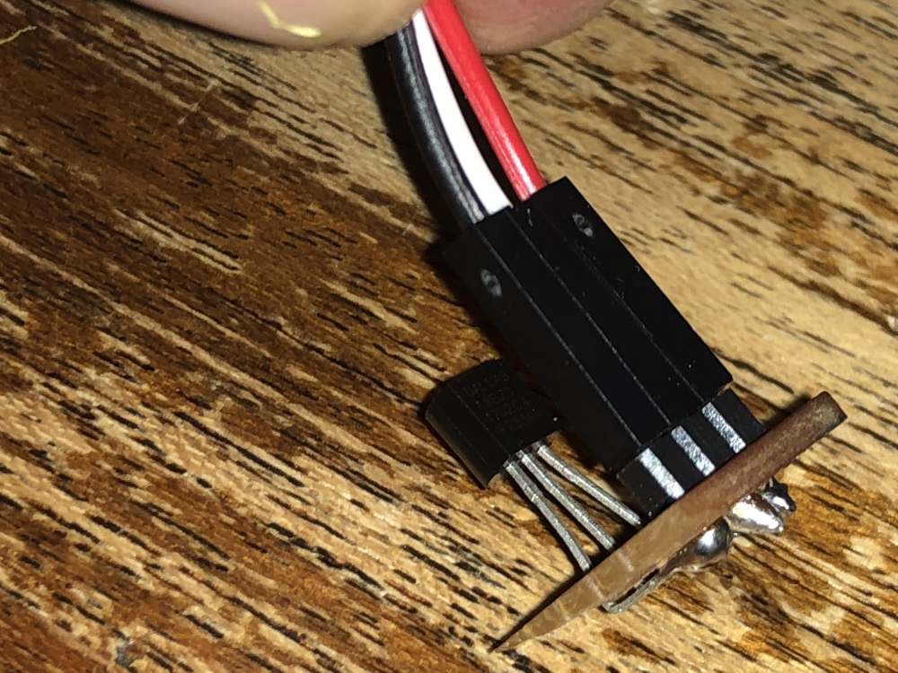
Dallas Temperature IC Control Library Demo Locating devices...Found 0 devices. Parasite power is: OFF Unable to find address for Device 0 Device 0 Address: 0000000000000000 Device 0 Resolution: 0 Requesting temperatures...DONE Temp C: -127.00 Temp F: -196.60 Requesting temperatures...DONE Temp C: -127.00 Temp F: -196.60 Requesting temperatures...DONE Temp C: -127.00 Temp F: -196.60 Requesting temperatures...DONE Temp C: -127.00 Temp F: -196.60 Requesting temperatures...DONE Temp C: -127.00 Temp F: -196.60 Requesting temperatures...DONE Temp C: -127.00 Temp F: -196.60 Requesting temperatures...DONE Temp C: -127.00 Temp F: -196.60 Requesting temperatures...DONE Temp C: -127.00 Temp F: -196.60 Requesting temperatures...DONE Temp C: -127.00 Temp F: -196.60 Requesting temperatures...DONE Temp C: -127.00 Temp F: -196.60 Requesting temperatures...DONE Temp C: -127.00 Temp F: -196.60@mr_sensor ok, so either it's not wired correctly (but it looks good), or it's a sensor failure or it's a failure between the sensor and the Arduino.
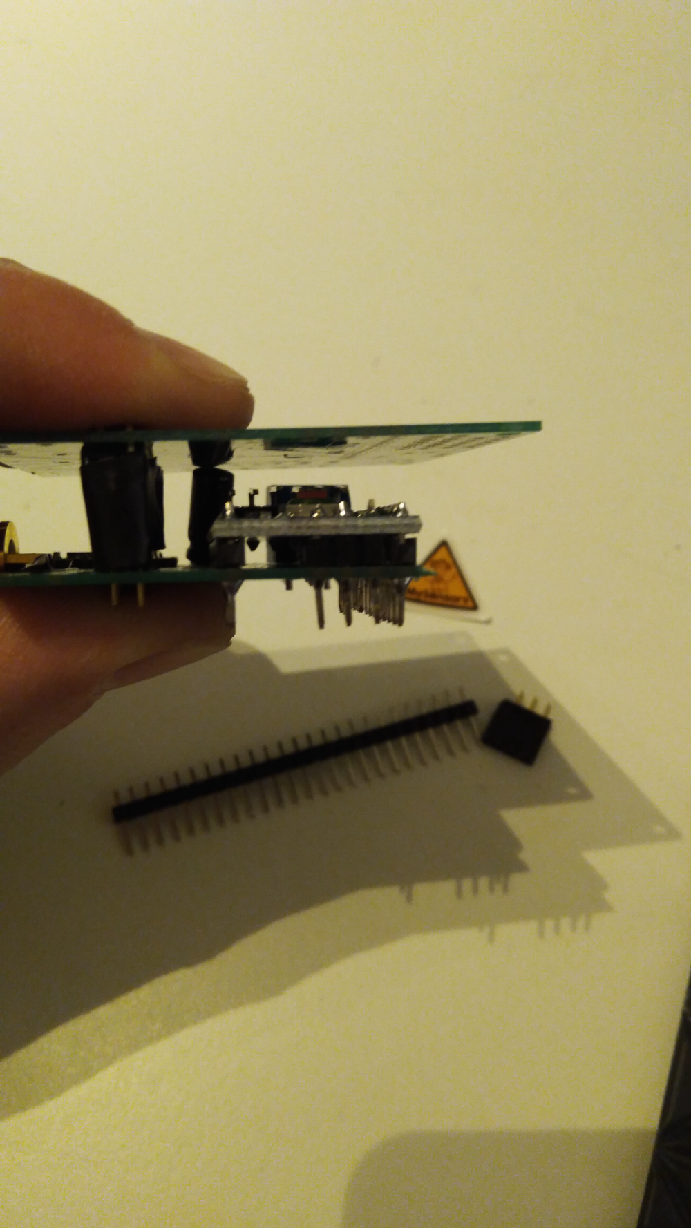
You can try to measure continuity from sensor to VCC / Gnd and D3 on the atmega.
-
@sundberg84 I run the "single" sketch from temp library and this is what I get:
Dallas Temperature IC Control Library Demo Locating devices...Found 0 devices. Parasite power is: OFF Unable to find address for Device 0 Device 0 Address: 0000000000000000 Device 0 Resolution: 0 Requesting temperatures...DONE Temp C: -127.00 Temp F: -196.60 Requesting temperatures...DONE Temp C: -127.00 Temp F: -196.60 Requesting temperatures...DONE Temp C: -127.00 Temp F: -196.60 Requesting temperatures...DONE Temp C: -127.00 Temp F: -196.60 Requesting temperatures...DONE Temp C: -127.00 Temp F: -196.60 Requesting temperatures...DONE Temp C: -127.00 Temp F: -196.60 Requesting temperatures...DONE Temp C: -127.00 Temp F: -196.60 Requesting temperatures...DONE Temp C: -127.00 Temp F: -196.60 Requesting temperatures...DONE Temp C: -127.00 Temp F: -196.60 Requesting temperatures...DONE Temp C: -127.00 Temp F: -196.60 Requesting temperatures...DONE Temp C: -127.00 Temp F: -196.60@mr_sensor And show a pic of the bottom of the board with the sensor.