💬 Sensebender Gateway
-
@MLs
Okay, simpler, forget what i told you, and follow my steps below. I've unstalled mine to show you ;)
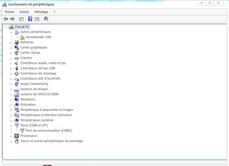
Then if it can be useful for others. Nothing fancy here, it can be used for lot of others drivers.Step 1: plugin the GW, as you can see it's not detected, and no additional com port.
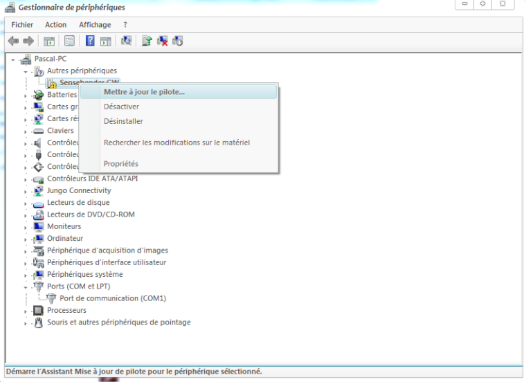
Step 2: right clic, and update driver
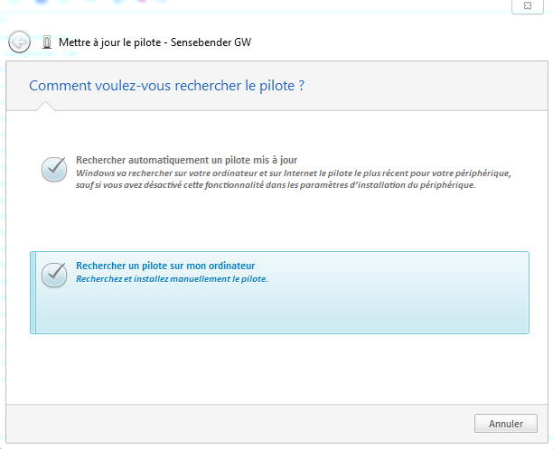
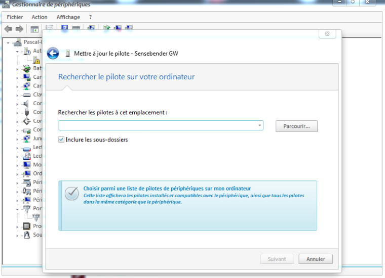
Step 3: click on the 2nd option for searching a driver on your machine
Step 4: Again 2nd option here (you want to search for a driver on your computer)
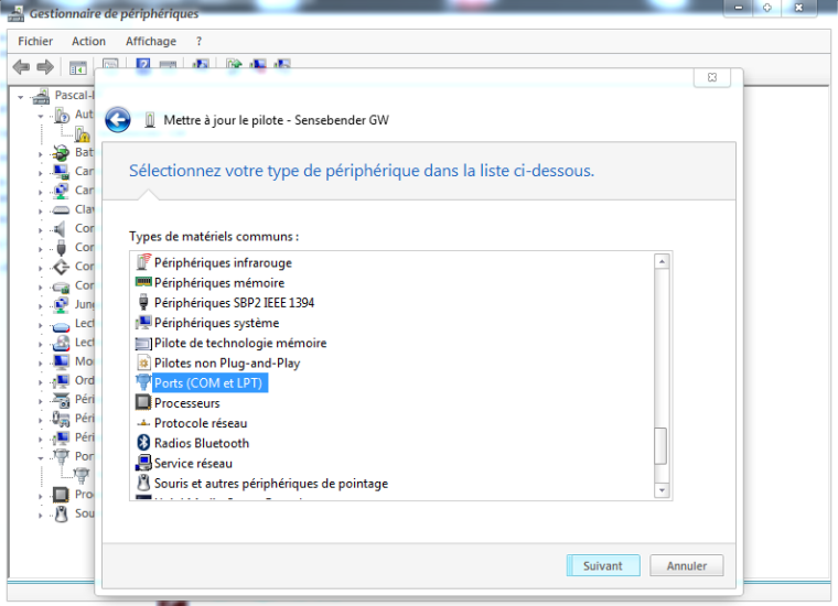
Step 5: This is a Virtual Serial Com port needed for the GW. So choose COM/LPT for the driver type
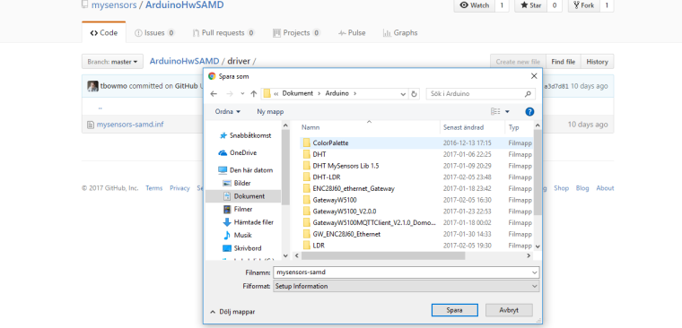
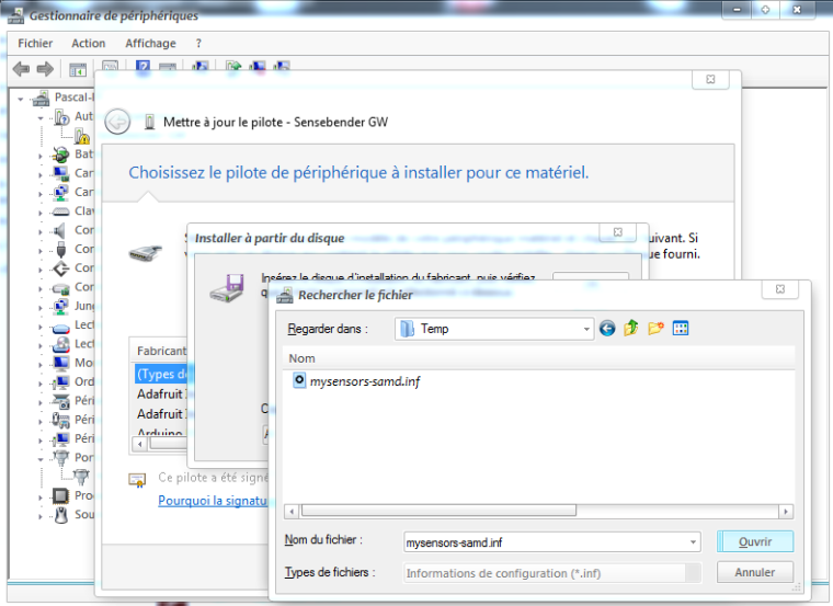
Step 6: Now it is asking where the driver (.inf) is stored
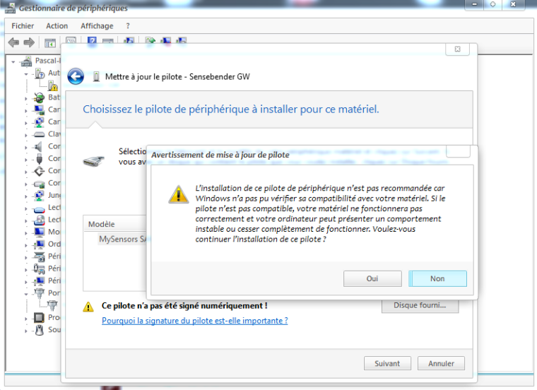
Step 7: You can now see that Windows knows what this is about. And tells you this driver is not "signed". No problem we know @tbowmo has done a great job. So, Next!
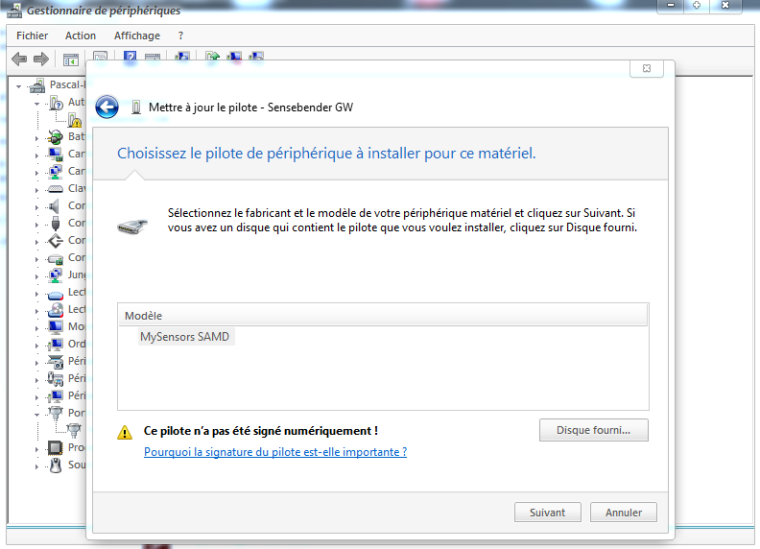
Step 8: Windows here warns again, saying he doesn't know this driver, so it may not work well. No way, it will work well ;) Click "Yes" to install it.
Step 9: Looks good
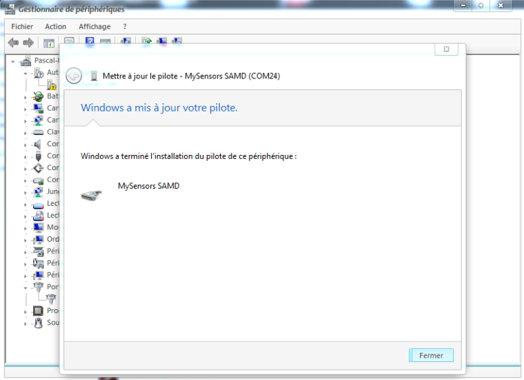
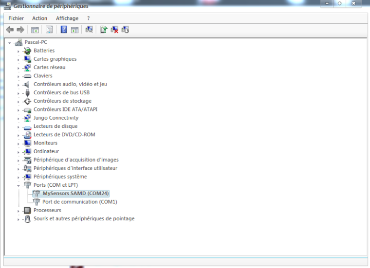
Step 10: Tada! Here you can see now the GW is well detected and setup on COM port 24
I can't do better!
I think you'll get it :) -
@MLs
Okay, simpler, forget what i told you, and follow my steps below. I've unstalled mine to show you ;)
Then if it can be useful for others. Nothing fancy here, it can be used for lot of others drivers.Step 1: plugin the GW, as you can see it's not detected, and no additional com port.
Step 2: right clic, and update driver
Step 3: click on the 2nd option for searching a driver on your machine
Step 4: Again 2nd option here (you want to search for a driver on your computer)
Step 5: This is a Virtual Serial Com port needed for the GW. So choose COM/LPT for the driver type
Step 6: Now it is asking where the driver (.inf) is stored
Step 7: You can now see that Windows knows what this is about. And tells you this driver is not "signed". No problem we know @tbowmo has done a great job. So, Next!
Step 8: Windows here warns again, saying he doesn't know this driver, so it may not work well. No way, it will work well ;) Click "Yes" to install it.
Step 9: Looks good
Step 10: Tada! Here you can see now the GW is well detected and setup on COM port 24
I can't do better!
I think you'll get it :)Thanks for a super instruction but it is the file itself that the computer says from. It says that the folder contains the no driver
And the driver in the folder I chose I downloaded here
https://github.com/mysensors/ArduinoHwSAMD/blob/master/driver/mysensors-samd.inf
// Mattias
-
Thanks for a super instruction but it is the file itself that the computer says from. It says that the folder contains the no driver
And the driver in the folder I chose I downloaded here
https://github.com/mysensors/ArduinoHwSAMD/blob/master/driver/mysensors-samd.inf
// Mattias
-
-
No, that will download a github html page.
Use the link I posted (and save as). It will be the raw content.
-
No, that will download a github html page.
Use the link I posted (and save as). It will be the raw content.
Now, I also got the computer to recognize the card. Thanks for all help.
The problem was that even when I used save as, the computer renaming the file as a .txt file "mysensors-samd.inf.txt" and not a "mysensors-samd.inf"
Again, thanks for all the help.
//Mattias
-
Hi together,
i have some questions to you! I bought a sensebender gateway and a w5100 Ethernet Modul, but i cant get it to work. When i upload the Gateway5100 Sketch and put my yip address in it, then the GW is booting up i get some Data on the serial port but i cant ping the configured ip address. Then i tried to config via DHCP and see that the GW dont get an IP Address.
And when i connect the NRF24 Modul then it seems that the GW is not bootin up anymore because i dont get any data on serial port.
i need your help. Thanks a lot in advance -
Hi tbowmo,
with the gatewayw5100 Sketch i get every 10 seconds 5 lines output on serial monitor:
The sketch is default i changed only the ip adress0;255;3;0;9;TSM:FAIL:RE-INIT 0;255;3;0;9;TSM:INIT 0;255;3;0;9;!TSM:INIT:TSP FAIL 0;255;3;0;9;TSM:FAIL:CNT=3 0;255;3;0;9;TSM:FAIL:PDT 0;255;3;0;9;TSM:FAIL:RE-INIT 0;255;3;0;9;TSM:INIT 0;255;3;0;9;!TSM:INIT:TSP FAIL 0;255;3;0;9;TSM:FAIL:CNT=4 0;255;3;0;9;TSM:FAIL:PDT 0;255;3;0;9;TSM:FAIL:RE-INIT 0;255;3;0;9;TSM:INIT 0;255;3;0;9;!TSM:INIT:TSP FAIL 0;255;3;0;9;TSM:FAIL:CNT=5 0;255;3;0;9;i dont know why, but i just uploaded the sensebenderserialgateway sketch and now i get this output:
0;255;3;0;9;MCO:BGN:INIT GW,CP=RNNGS--,VER=2.1.1
0;255;3;0;9;TSF:LRT:OK
0;255;3;0;9;TSM:INIT
0;255;3;0;9;TSF:WUR:MS=0
0;255;3;0;9;TSM:INIT:TSP OK
0;255;3;0;9;TSM:INIT:GW MODE
0;255;3;0;9;TSM:READY:ID=0,PAR=0,DIS=0
0;255;3;0;9;MCO:REG:NOT NEEDED
0;255;3;0;14;Gateway startup complete.
0;255;0;0;18;2.1.1
0;255;3;0;9;MCO:BGN:STP
0;255;3;0;9;
the NRF Module is connected! Now i need to get the w5100 module to work.
-
Ok i just connected the W5100 and NRF24 Module and uploaded the GatewayW5100 Sketch and when the upload is done after reset i dont get any output on serial monitor.
The orange, green and red led are lighting.When i upload the SensebenderGatewaySerial then i get output on serial monitor. It think the problem must be the w5100. But what going wrong?
-
i have only changed the ip adress
here is the sketch:/** * The MySensors Arduino library handles the wireless radio link and protocol * between your home built sensors/actuators and HA controller of choice. * The sensors forms a self healing radio network with optional repeaters. Each * repeater and gateway builds a routing tables in EEPROM which keeps track of the * network topology allowing messages to be routed to nodes. * * Created by Henrik Ekblad <henrik.ekblad@mysensors.org> * Copyright (C) 2013-2015 Sensnology AB * Full contributor list: https://github.com/mysensors/Arduino/graphs/contributors * * Documentation: http://www.mysensors.org * Support Forum: http://forum.mysensors.org * * This program is free software; you can redistribute it and/or * modify it under the terms of the GNU General Public License * version 2 as published by the Free Software Foundation. * ******************************* * * REVISION HISTORY * Version 1.0 - Henrik EKblad * Contribution by a-lurker and Anticimex, * Contribution by Norbert Truchsess <norbert.truchsess@t-online.de> * Contribution by Tomas Hozza <thozza@gmail.com> * * * DESCRIPTION * The EthernetGateway sends data received from sensors to the ethernet link. * The gateway also accepts input on ethernet interface, which is then sent out to the radio network. * * The GW code is designed for Arduino 328p / 16MHz. ATmega168 does not have enough memory to run this program. * * LED purposes: * - To use the feature, uncomment MY_DEFAULT_xxx_LED_PIN in the sketch below * - RX (green) - blink fast on radio message recieved. In inclusion mode will blink fast only on presentation recieved * - TX (yellow) - blink fast on radio message transmitted. In inclusion mode will blink slowly * - ERR (red) - fast blink on error during transmission error or recieve crc error * * See http://www.mysensors.org/build/ethernet_gateway for wiring instructions. * */ // Enable debug prints to serial monitor #define MY_DEBUG // Enable and select radio type attached #define MY_RADIO_NRF24 //#define MY_RADIO_RFM69 // Enable gateway ethernet module type #define MY_GATEWAY_W5100 // W5100 Ethernet module SPI enable (optional if using a shield/module that manages SPI_EN signal) //#define MY_W5100_SPI_EN 4 // Enable Soft SPI for NRF radio (note different radio wiring is required) // The W5100 ethernet module seems to have a hard time co-operate with // radio on the same spi bus. #if !defined(MY_W5100_SPI_EN) && !defined(ARDUINO_ARCH_SAMD) #define MY_SOFTSPI #define MY_SOFT_SPI_SCK_PIN 14 #define MY_SOFT_SPI_MISO_PIN 16 #define MY_SOFT_SPI_MOSI_PIN 15 #endif // When W5100 is connected we have to move CE/CSN pins for NRF radio #ifndef MY_RF24_CE_PIN #define MY_RF24_CE_PIN 5 #endif #ifndef MY_RF24_CS_PIN #define MY_RF24_CS_PIN 6 #endif // Enable to UDP //#define MY_USE_UDP #define MY_IP_ADDRESS 10,0,0,253 // If this is disabled, DHCP is used to retrieve address // Renewal period if using DHCP //#define MY_IP_RENEWAL_INTERVAL 60000 // The port to keep open on node server mode / or port to contact in client mode #define MY_PORT 5003 // Controller ip address. Enables client mode (default is "server" mode). // Also enable this if MY_USE_UDP is used and you want sensor data sent somewhere. //#define MY_CONTROLLER_IP_ADDRESS 192, 168, 178, 254 // The MAC address can be anything you want but should be unique on your network. // Newer boards have a MAC address printed on the underside of the PCB, which you can (optionally) use. // Note that most of the Ardunio examples use "DEAD BEEF FEED" for the MAC address. #define MY_MAC_ADDRESS 0xDE, 0xAD, 0xBE, 0xEF, 0xFE, 0xED // Enable inclusion mode #define MY_INCLUSION_MODE_FEATURE // Enable Inclusion mode button on gateway //#define MY_INCLUSION_BUTTON_FEATURE // Set inclusion mode duration (in seconds) #define MY_INCLUSION_MODE_DURATION 60 // Digital pin used for inclusion mode button //#define MY_INCLUSION_MODE_BUTTON_PIN 3 // Set blinking period #define MY_DEFAULT_LED_BLINK_PERIOD 300 // Flash leds on rx/tx/err // Uncomment to override default HW configurations //#define MY_DEFAULT_ERR_LED_PIN 7 // Error led pin //#define MY_DEFAULT_RX_LED_PIN 8 // Receive led pin //#define MY_DEFAULT_TX_LED_PIN 9 // Transmit led pin #if defined(MY_USE_UDP) #include <EthernetUdp.h> #endif #include <Ethernet.h> #include <MySensors.h> void setup() { } void loop() { }``` -
i have only changed the ip adress
here is the sketch:/** * The MySensors Arduino library handles the wireless radio link and protocol * between your home built sensors/actuators and HA controller of choice. * The sensors forms a self healing radio network with optional repeaters. Each * repeater and gateway builds a routing tables in EEPROM which keeps track of the * network topology allowing messages to be routed to nodes. * * Created by Henrik Ekblad <henrik.ekblad@mysensors.org> * Copyright (C) 2013-2015 Sensnology AB * Full contributor list: https://github.com/mysensors/Arduino/graphs/contributors * * Documentation: http://www.mysensors.org * Support Forum: http://forum.mysensors.org * * This program is free software; you can redistribute it and/or * modify it under the terms of the GNU General Public License * version 2 as published by the Free Software Foundation. * ******************************* * * REVISION HISTORY * Version 1.0 - Henrik EKblad * Contribution by a-lurker and Anticimex, * Contribution by Norbert Truchsess <norbert.truchsess@t-online.de> * Contribution by Tomas Hozza <thozza@gmail.com> * * * DESCRIPTION * The EthernetGateway sends data received from sensors to the ethernet link. * The gateway also accepts input on ethernet interface, which is then sent out to the radio network. * * The GW code is designed for Arduino 328p / 16MHz. ATmega168 does not have enough memory to run this program. * * LED purposes: * - To use the feature, uncomment MY_DEFAULT_xxx_LED_PIN in the sketch below * - RX (green) - blink fast on radio message recieved. In inclusion mode will blink fast only on presentation recieved * - TX (yellow) - blink fast on radio message transmitted. In inclusion mode will blink slowly * - ERR (red) - fast blink on error during transmission error or recieve crc error * * See http://www.mysensors.org/build/ethernet_gateway for wiring instructions. * */ // Enable debug prints to serial monitor #define MY_DEBUG // Enable and select radio type attached #define MY_RADIO_NRF24 //#define MY_RADIO_RFM69 // Enable gateway ethernet module type #define MY_GATEWAY_W5100 // W5100 Ethernet module SPI enable (optional if using a shield/module that manages SPI_EN signal) //#define MY_W5100_SPI_EN 4 // Enable Soft SPI for NRF radio (note different radio wiring is required) // The W5100 ethernet module seems to have a hard time co-operate with // radio on the same spi bus. #if !defined(MY_W5100_SPI_EN) && !defined(ARDUINO_ARCH_SAMD) #define MY_SOFTSPI #define MY_SOFT_SPI_SCK_PIN 14 #define MY_SOFT_SPI_MISO_PIN 16 #define MY_SOFT_SPI_MOSI_PIN 15 #endif // When W5100 is connected we have to move CE/CSN pins for NRF radio #ifndef MY_RF24_CE_PIN #define MY_RF24_CE_PIN 5 #endif #ifndef MY_RF24_CS_PIN #define MY_RF24_CS_PIN 6 #endif // Enable to UDP //#define MY_USE_UDP #define MY_IP_ADDRESS 10,0,0,253 // If this is disabled, DHCP is used to retrieve address // Renewal period if using DHCP //#define MY_IP_RENEWAL_INTERVAL 60000 // The port to keep open on node server mode / or port to contact in client mode #define MY_PORT 5003 // Controller ip address. Enables client mode (default is "server" mode). // Also enable this if MY_USE_UDP is used and you want sensor data sent somewhere. //#define MY_CONTROLLER_IP_ADDRESS 192, 168, 178, 254 // The MAC address can be anything you want but should be unique on your network. // Newer boards have a MAC address printed on the underside of the PCB, which you can (optionally) use. // Note that most of the Ardunio examples use "DEAD BEEF FEED" for the MAC address. #define MY_MAC_ADDRESS 0xDE, 0xAD, 0xBE, 0xEF, 0xFE, 0xED // Enable inclusion mode #define MY_INCLUSION_MODE_FEATURE // Enable Inclusion mode button on gateway //#define MY_INCLUSION_BUTTON_FEATURE // Set inclusion mode duration (in seconds) #define MY_INCLUSION_MODE_DURATION 60 // Digital pin used for inclusion mode button //#define MY_INCLUSION_MODE_BUTTON_PIN 3 // Set blinking period #define MY_DEFAULT_LED_BLINK_PERIOD 300 // Flash leds on rx/tx/err // Uncomment to override default HW configurations //#define MY_DEFAULT_ERR_LED_PIN 7 // Error led pin //#define MY_DEFAULT_RX_LED_PIN 8 // Receive led pin //#define MY_DEFAULT_TX_LED_PIN 9 // Transmit led pin #if defined(MY_USE_UDP) #include <EthernetUdp.h> #endif #include <Ethernet.h> #include <MySensors.h> void setup() { } void loop() { }```So I think i have a maybe already solved issue, but I can not get int working...
In Arduino IDE 1.8.1 this is the error during compiling:"Local\Arduino15\packages\arduino\hardware\samd\1.6.12\cores\arduino/Arduino.h:48:17: fatal error: sam.h: No such file or directory"
-
I have the MySensors SAMD boards installed, so Sensbender Gateway is availabe
-
Arduino SAMD boards are also installed
-
I have installed the "M0" boards
-
Running windows 10 so no need for the inf file, is this correct?
what am I missing?
thanks in advance!
-
-
So I think i have a maybe already solved issue, but I can not get int working...
In Arduino IDE 1.8.1 this is the error during compiling:"Local\Arduino15\packages\arduino\hardware\samd\1.6.12\cores\arduino/Arduino.h:48:17: fatal error: sam.h: No such file or directory"
-
I have the MySensors SAMD boards installed, so Sensbender Gateway is availabe
-
Arduino SAMD boards are also installed
-
I have installed the "M0" boards
-
Running windows 10 so no need for the inf file, is this correct?
what am I missing?
thanks in advance!
-
-
@jeti SAMD board defs 1.6.12 are currently not supported (PR filed) - you need to downgrade to 1.6.11 until the PR is merged.
-
It's has been a long time since I've posted on this forum.Today I received a note form the postal service that a package from a foreign country has arrived at my local postal office. Can't wait until tomorrow, just to see this beauty.
Now I have to find some time to get it running ;-(
-
It's has been a long time since I've posted on this forum.Today I received a note form the postal service that a package from a foreign country has arrived at my local postal office. Can't wait until tomorrow, just to see this beauty.
Now I have to find some time to get it running ;-(