💬 Very narrow and minimal switch node
-
Dear
I ordered a few...:-)
Do you have a working sketch that is using less power?
Perhaps wit a motionsensor and a DHt ore something
I hope i get you hardware working..@Dombo71
Motion sensors are also not so low power and as mentioned before, DHT are power hungry. SI7021 is much better for low power/low voltage use. -
@Dombo71
What do you mean with "using less power"?@GertSanders said:
SI7021
I hope i can make a 3 in 1 sensor
Motion / contact.
temp and humanity
Better should be a multisensor, with a lot of option so we can choose .
The examples on my sensor are most 1 sensor...And then work on a battery[s] for a year
Thanks for the SI7021 tip..
Domoticz, with a lot of working hardware, include mysensors :-)
OpenPLI, RuneAudio, Solarmeter, etc......Not a great builder of software and hardware, more a user...
Only i try to do my best :-( -
@GertSanders said:
SI7021
I hope i can make a 3 in 1 sensor
Motion / contact.
temp and humanity
Better should be a multisensor, with a lot of option so we can choose .
The examples on my sensor are most 1 sensor...And then work on a battery[s] for a year
Thanks for the SI7021 tip..
This board is not meant for more then 1 function.
-
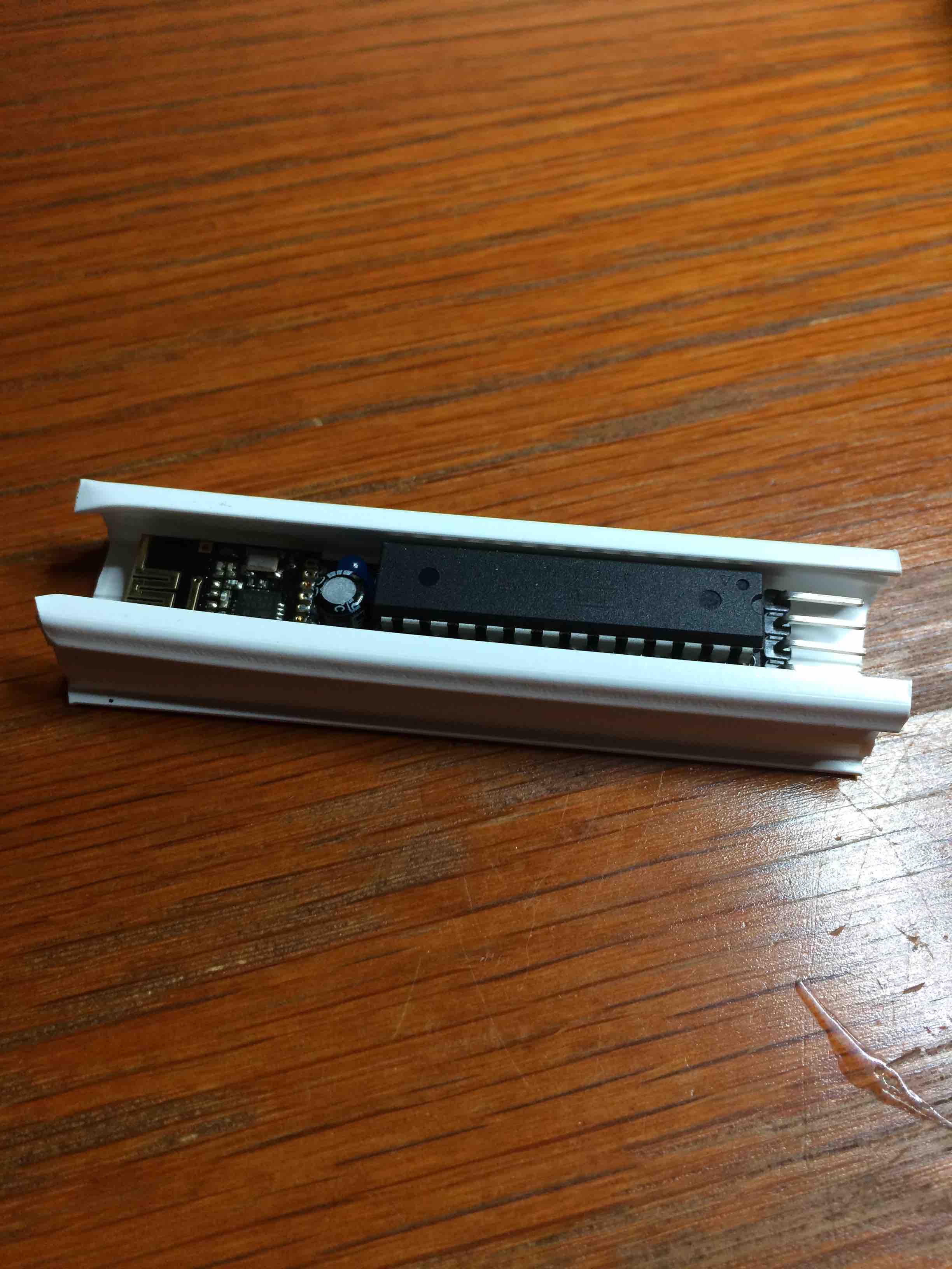
@GertSanders How snug is your enclosure? I saw @m26872 used 17x20mm for his slim node, but I was able to find in the UK 16x16mm trunking, which I think maybe a little bit small.
-
@GertSanders How snug is your enclosure? I saw @m26872 used 17x20mm for his slim node, but I was able to find in the UK 16x16mm trunking, which I think maybe a little bit small.
@alexsh1
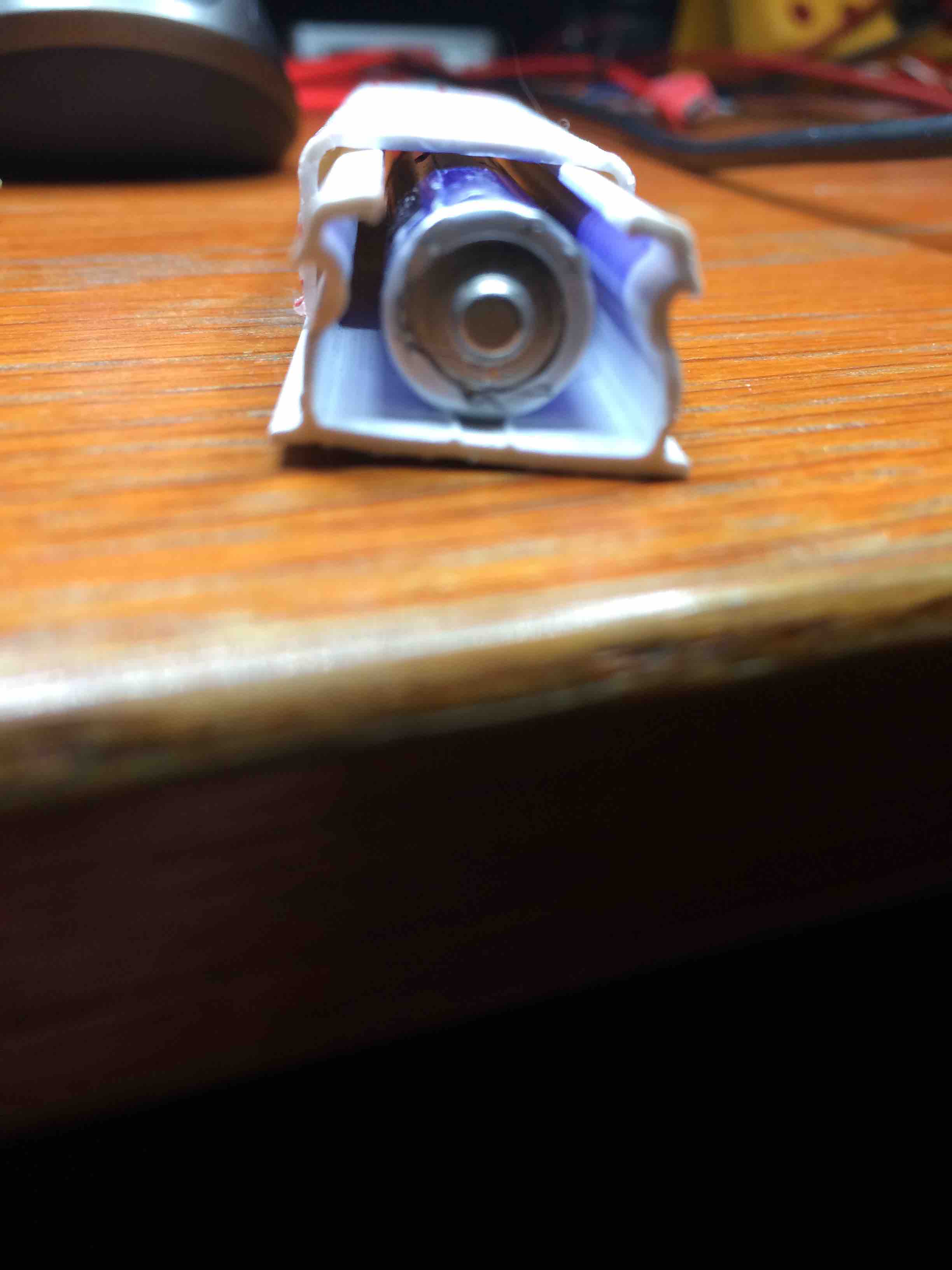
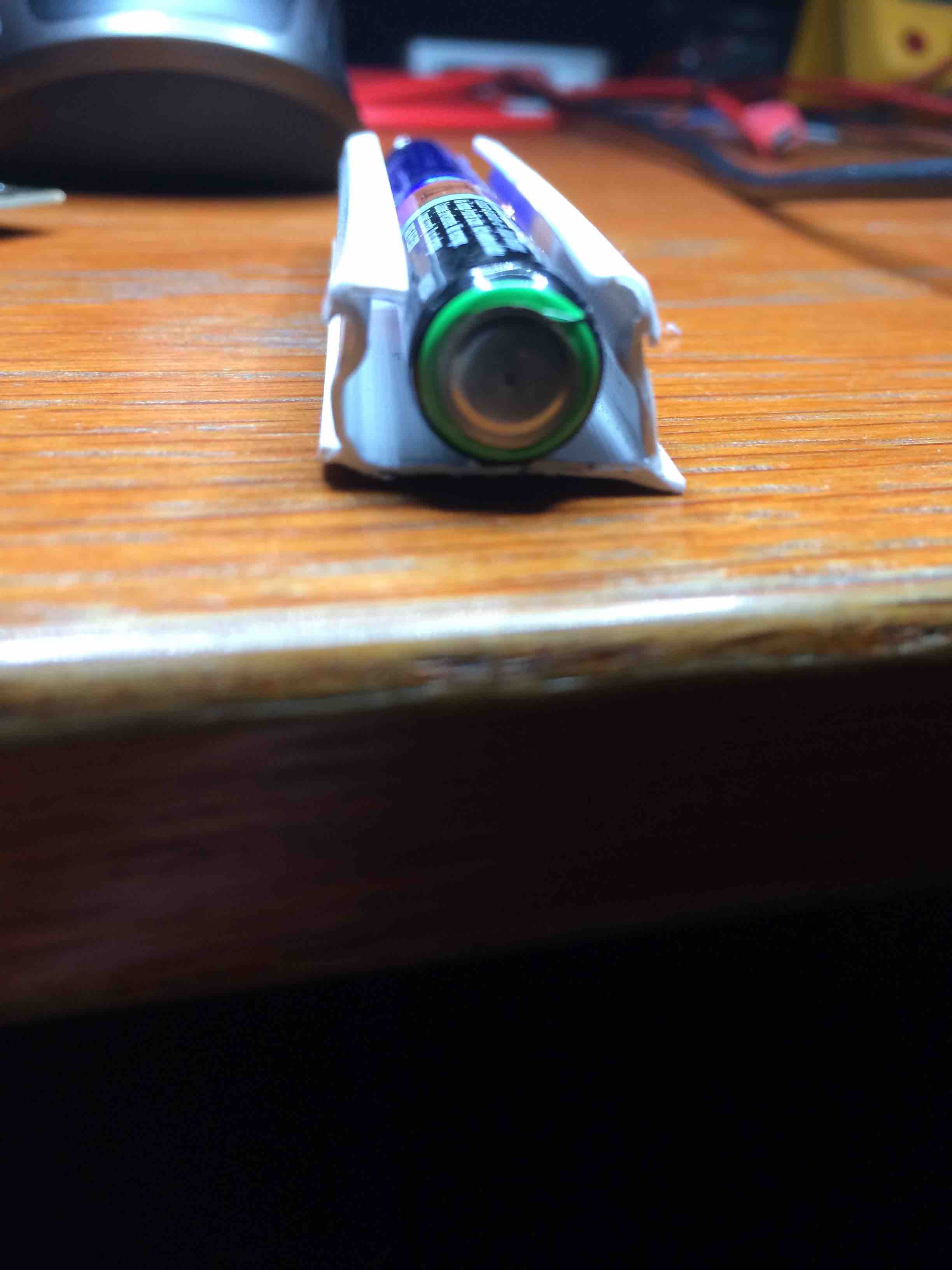
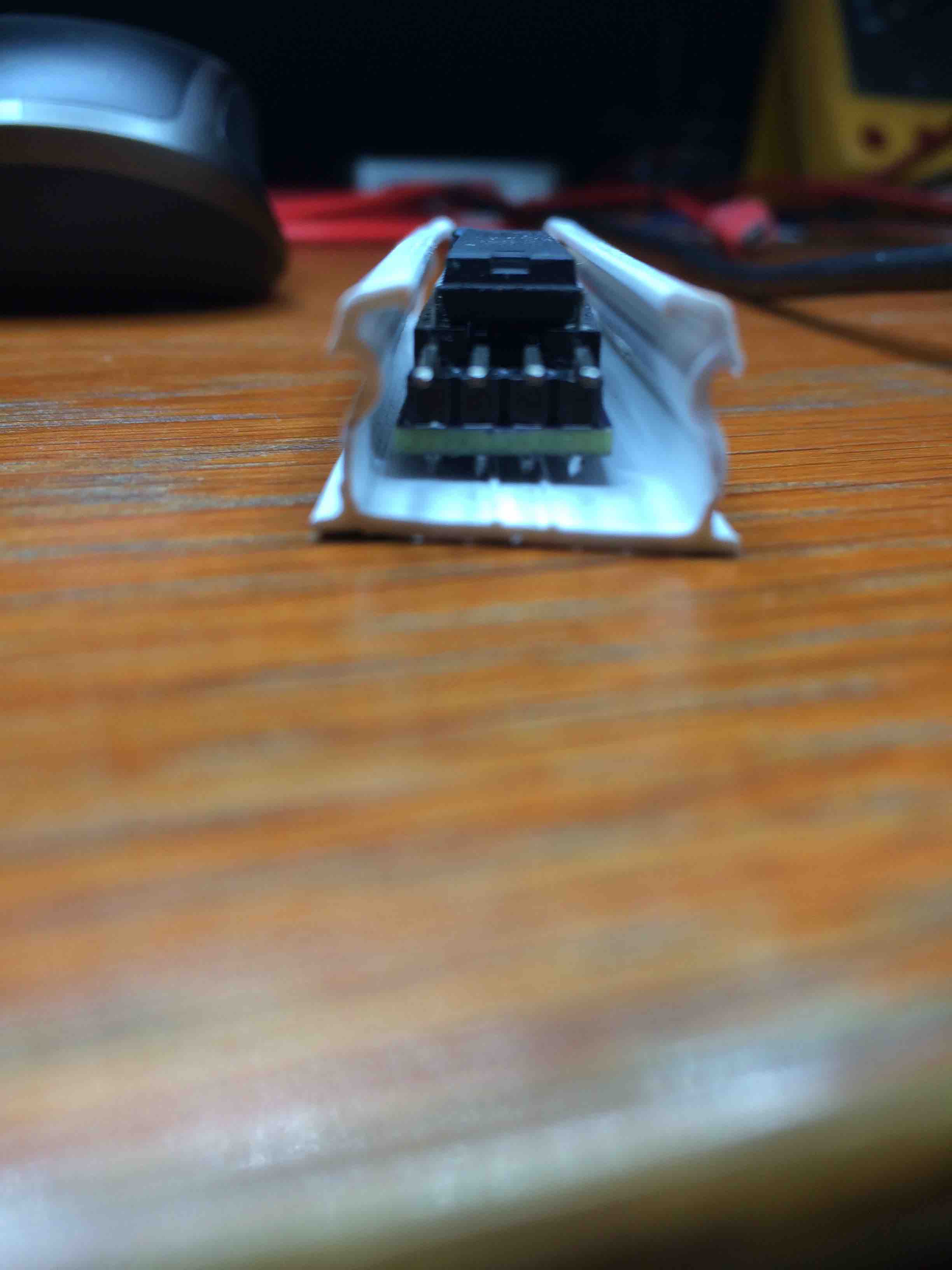
I also use a 16x16mm cable guide and it just fits, the batteries are in batteryholders and therefor they stick out by 1mm. Without the batteryholder they fit perfectly.
The board is 13mm wide at the base which allows passing a few wires next to it. So 16x16 is ok for my narrow board. -
@GertSanders How snug is your enclosure? I saw @m26872 used 17x20mm for his slim node, but I was able to find in the UK 16x16mm trunking, which I think maybe a little bit small.
Here are some images of the very narrow node in a 16x16mm cable duct. The batteries are AAA type.
-
@GertSanders - Thanks for photos. I have got 16x16mm trunking and just waiting for some spare parts. Will be posting photos shortly.
-
@alexsh1
I also use a 16x16mm cable guide and it just fits, the batteries are in batteryholders and therefor they stick out by 1mm. Without the batteryholder they fit perfectly.
The board is 13mm wide at the base which allows passing a few wires next to it. So 16x16 is ok for my narrow board.This option with a pir...
or a magnet sensor.
What is the battery live?Domoticz, with a lot of working hardware, include mysensors :-)
OpenPLI, RuneAudio, Solarmeter, etc......Not a great builder of software and hardware, more a user...
Only i try to do my best :-( -
This option with a pir...
or a magnet sensor.
What is the battery live?@Dylano said:
This option with a pir...
or a magnet sensor.This is more a reed sensor. For PIR the size is just not right IMHO.
Given that it sleeps most of the time, the battary life should be excellent.
I do not know, maybe @GertSanders has got more comments? -
@Dylano said:
This option with a pir...
or a magnet sensor.This is more a reed sensor. For PIR the size is just not right IMHO.
Given that it sleeps most of the time, the battary life should be excellent.
I do not know, maybe @GertSanders has got more comments?@alexsh1 with a switch (reed or mechanical) i see a consumption of around 5micro amperes in sleep mode. 2 AAA should last minimum a year. We will see as my node is only started last week.
A small PIR sensor is possible, see the "small AA project" and the mini PIR example.
http://forum.mysensors.org/topic/2715/slim-node-as-a-mini-2aa-battery-pir-motion-sensor
No idea what lifetime to expect there.
-
I've just ordered a batch of these. Really cool, I can't wait to receive them. Thanks for the great work!
-
YES, my first is working. More to make. In my home now: "Big brother is watching you" Placed my first at the door of the refrigerator ;-)
@GertSanders, you write:
powering something with low consumption
You can set both pins D2 and D3 of the processor to OUTPUT, do not mount the pull up resistors, do not activate the internal PullUPs, and by setting one of the pins to HIGH and the other to LOW you can power something. You will need to take care that a maximum of 20mA is consumed, as this is the recommended maximum amperage the pins of the atmega328 can drive or source.Sure not to mount the pull up resistors. But how do de-activate the internal PullUPs, and by setting one of the pins to HIGH and the other to LOW.
Can you explain in "jip en Janneke/suske en wiske" language how to. With the help of this site I made my first one:
https://forum.mysensors.org/topic/3018/tutorial-how-to-burn-1mhz-8mhz-bootloader-using-arduino-ide-1-6-5-r5 -
YES, my first is working. More to make. In my home now: "Big brother is watching you" Placed my first at the door of the refrigerator ;-)
@GertSanders, you write:
powering something with low consumption
You can set both pins D2 and D3 of the processor to OUTPUT, do not mount the pull up resistors, do not activate the internal PullUPs, and by setting one of the pins to HIGH and the other to LOW you can power something. You will need to take care that a maximum of 20mA is consumed, as this is the recommended maximum amperage the pins of the atmega328 can drive or source.Sure not to mount the pull up resistors. But how do de-activate the internal PullUPs, and by setting one of the pins to HIGH and the other to LOW.
Can you explain in "jip en Janneke/suske en wiske" language how to. With the help of this site I made my first one:
https://forum.mysensors.org/topic/3018/tutorial-how-to-burn-1mhz-8mhz-bootloader-using-arduino-ide-1-6-5-r5@Bolliebol
You need to use these instructions:void setup()
{
pinMode(2, OUTPUT);
digitalWrite(2, HIGH);
pinMode(3, OUTPUT);
digitalWrite(2, LOW);// this makes pin 2 the "plus" side and pin 3 the "minus" side.
// Connect your low power consuming thing between these two pins as if they are battery pins.
// If you need to power off the device, just do
digitalWrite(2,LOW);
}
-
To anyone wanting to build this project: take note that it uses machine pin female headers to seat the mcu. Ordinary female headers won't make a good enough connection with the legs of the atmega328.
-
Hi, I have finally receive your narrow board.. I try with a Si7021 sensor (the GY-21 ebay version) and I have no success. But with your other board, because I have your 2 other board version (ac/dc board and the small battery one) it's working with no problem. The difference I think is the first board without external crystal. After reading in forum, I think with Slim board version, i'm not the first with this problem. Did you test your board with si7021 sensor, or can you give my a clue ?? Thanks
-
@Carl-H did you have an error message? Providing logs would also help. Which address and library did you use for this sensor please?
@alexsh1 I use the this lib: https://github.com/LowPowerLab/SI7021 My board freeze when initialize with begin function.
I can't have the error exactly because this board don't have any FTDI connection. But the same atmega328p chip with other board, it's working !! I think again is it because the board use internal oscillator.
-
@alexsh1 I use the this lib: https://github.com/LowPowerLab/SI7021 My board freeze when initialize with begin function.
I can't have the error exactly because this board don't have any FTDI connection. But the same atmega328p chip with other board, it's working !! I think again is it because the board use internal oscillator.
@Carl-H if your atmega328p programmed to use the internal oscillator, I do not think this would cause a problem with Si7021.
You most likely need to assemble the same on the breadboard and connect the FTDI - I would be a simple error. Once I had a problem with Si7021 using a different address to the one in the library. Took me a while to troubleshoot.
Without logs, this is a pure guess unfortunately -
@alexsh1 I use the this lib: https://github.com/LowPowerLab/SI7021 My board freeze when initialize with begin function.
I can't have the error exactly because this board don't have any FTDI connection. But the same atmega328p chip with other board, it's working !! I think again is it because the board use internal oscillator.
@Carl-H
Did you order the latest version of the slim board ? It has solderjumpers you need to use if you want the SCL/SDA pins connected.
If there is no solderbridge on either solderpad, the D2, SDA and SCL of the atmega are not connected. This board also requires the fuses of the atmega to be set to internal oscillator as there is no external crystal.