Solar Powered Soil Moisture Sensor
-
To have in mind
If you use the lamp with silver stick, it is metal, then remember to protect the battery if you but the battery in the stick.
Use hot glue at the top around the solar otherwise rain will stay between the solar and the place where it is mounted. I don't get water inside where the electronics are but you never know what will happen after a few month.
I have some problem with my black lamp it is rust on the positive connection, today it stopped working because if this, I had to remove the connection and put it back.
Recommend to solder the cable instead of using connectors, which I do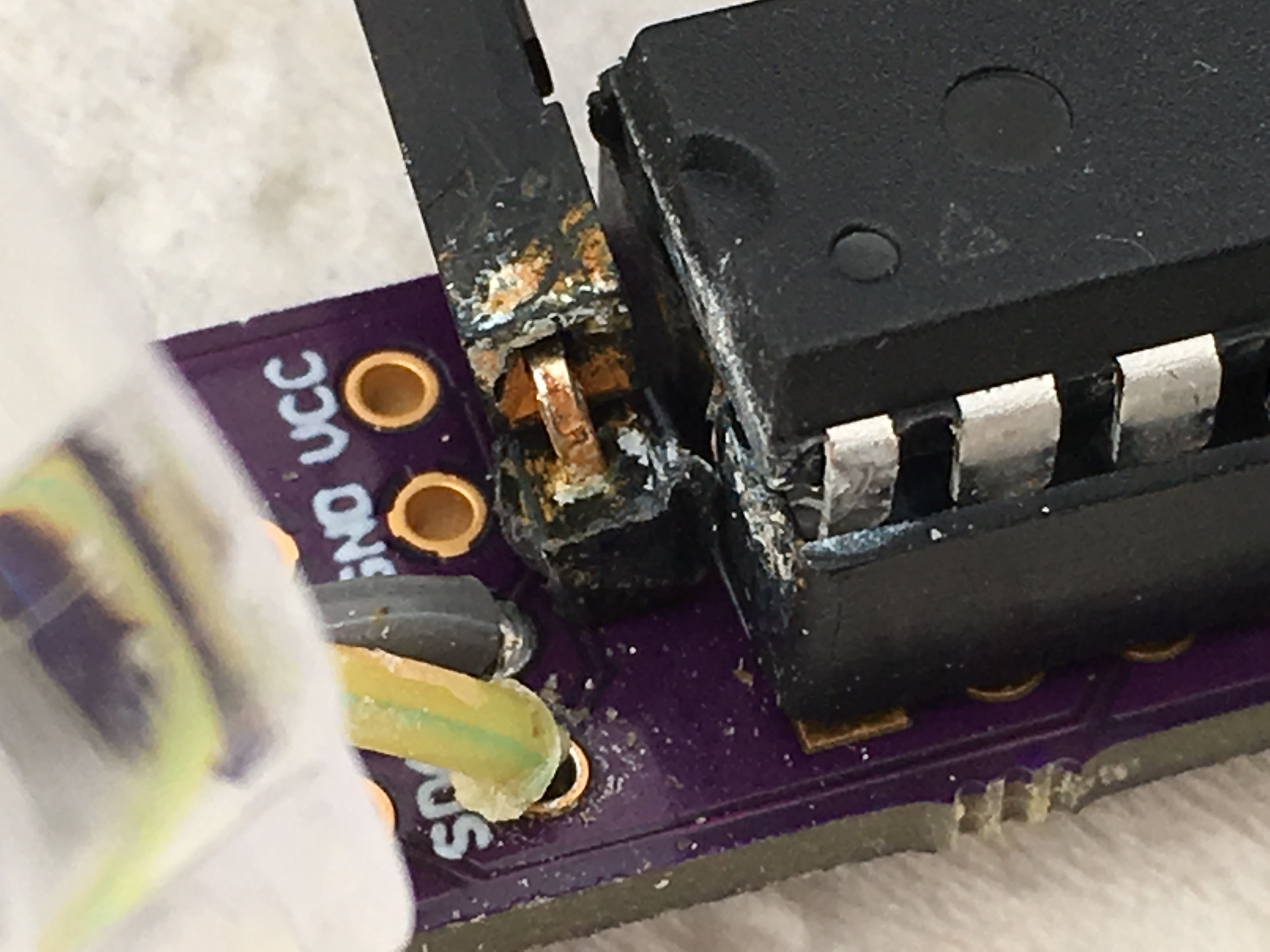
-
To have in mind
If you use the lamp with silver stick, it is metal, then remember to protect the battery if you but the battery in the stick.
Use hot glue at the top around the solar otherwise rain will stay between the solar and the place where it is mounted. I don't get water inside where the electronics are but you never know what will happen after a few month.
I have some problem with my black lamp it is rust on the positive connection, today it stopped working because if this, I had to remove the connection and put it back.
Recommend to solder the cable instead of using connectors, which I doFirst, thank you very much for making these tests, I found some similar garden lamps in a local store and thought they were cheap so I bought one to have a look. Seems they were not so cheap as I paid nearly 3$ despite living in a developing country :D
I will make a test with it as soon as I find a step up accepting the 1.xV of the battery, but I'm not sure if it will really work as the battery inside mine is a tiny V80h with a very limited 60mAh capacity, not sure if it will survive the sending of data...@flopp said:
I have some problem with my black lamp it is rust on the positive connection, today it stopped working because if this, I had to remove the connection and put it back.
Recommend to solder the cable instead of using connectors, which I do!I would put some hot glue there too, no ? When all connections are checked and the board is running fine you could even sink the whole electronic in hot glue to solve these problems "forever" ?
-
First, thank you very much for making these tests, I found some similar garden lamps in a local store and thought they were cheap so I bought one to have a look. Seems they were not so cheap as I paid nearly 3$ despite living in a developing country :D
I will make a test with it as soon as I find a step up accepting the 1.xV of the battery, but I'm not sure if it will really work as the battery inside mine is a tiny V80h with a very limited 60mAh capacity, not sure if it will survive the sending of data...@flopp said:
I have some problem with my black lamp it is rust on the positive connection, today it stopped working because if this, I had to remove the connection and put it back.
Recommend to solder the cable instead of using connectors, which I do!I would put some hot glue there too, no ? When all connections are checked and the board is running fine you could even sink the whole electronic in hot glue to solve these problems "forever" ?
@Nca78 said:
First, thank you very much for making these tests, I found some similar garden lamps in a local store and thought they were cheap so I bought one to have a look. Seems they were not so cheap as I paid nearly 3$ despite living in a developing country :D
Thank you. $3 is not bad but expensive compared to mine :)
I will make a test with it as soon as I find a step up accepting the 1.xV of the battery, but I'm not sure if it will really work as the battery inside mine is a tiny V80h with a very limited 60mAh capacity, not sure if it will survive the sending of data...
This is what I use as step-up, search for that product you will find cheaper than $1.49
http://www.ebay.com/itm/DC-DC-0-8-3V-to-3-3V-Step-UP-Boost-Power-Board-Module-Converter-Voltage-RF-/282029936915?hash=item41aa4b5113:g:3GAAAOSw1DtXLS7QI would put some hot glue there too, no ? When all connections are checked and the board is running fine you could even sink the whole electronic in hot glue to solve these problems "forever" ?
Yes, why not, sounds like a good idea. But keep TX, RX, RESET and GND available to be able to update the sketch
-
The "lamp"(silver) that I run out of battery seems to be damaged, two days ago it stopped sending data, last reported voltage was 1.13V which is good enough to work.
Maybe the battery got damaged, it is a NiMh and I think they have some kind of memory?
But why doesn't it get damage when you use the lamp as a lamp?
Normally the lamp is charging the battery during the day and when it is dark it power on a LED which will lit until the battery is empty or maybe until the IC(YX8018) measure a low voltage.Today I change my second "lamp"(black) to a 1.2v AAA NiMh2 800mAh. I think this will help to not getting to low voltage during night.
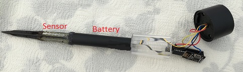
The battery that was included was mounted in the lid, I removed it and placed the new battery in the stick.
I also made the stick little bit shorter, but don't make it too short because then you will measure the moisture at the top of the soil.
The black round stick is 9 cm and the whole thing, when put togehter, is 28 cm from top(solar) to bottom(tip)
-
@flopp you attached your sensors by two differant methods. Which methods seems to be working the best?
@gbgent_nc
The sensor itself is connected the same way, A4 and A5 on both. @gbgent_nc if you mean that one is glued, that is difficult to say if it makes any difference. I tried lamp1 and 2 in same soil but they always had ~10% difference, I also tried same sensor both glued in same soil still difference. You have to measure until the flower/vegetable is dry and check your percentage after this you can set an alarm on that percentage. E.g. I have spices with 30% when it is dry and a flower that right now is 20% and not dry, maybe different soil etc.
I recommend to glue the sensor on the arrow, otherwise it is very difficult to remove the lamp from soil, the sensor with stay in soil and you have to dig it out :)
I had a test with a cap connected to my voltage measurement A0, but it didn't make any difference. No need to use Cap.
I use other battery on one "lamp" only to be able to measure many days without sun.Today I have 3 lamps, yesterday number 3 was put in the soil. I now measure every hour, before every 30 minutes.
-
I have a couple soil sensors running with simple bolts in the ground. No two sensors will read the same in the same soil, but that is because they are just a relative setup not an accurate setup. Doing what is recommended above is necessary. Determine what % correlates to watering time on the plants. Once this is done it is set and forget.
Also, on your batteries
"The phenomenon itself is very real. If a NiCd battery is repeatedly charged after it has only been partially discharged it will develop a lower voltage and a lower capacity. Fortunately, this effect is reversible by conditioning NiCds."So I vote to help your poor cheap lamp batteries out by writing logic into your arduino that varies by battery voltage. You can write it in ranges
battery > X volts report every Y minutes
battery > Z volts report every P minutes
battery > .....etcalso to keep your battery in good shape you may consider every so many days ( 2 - 5 ) writing logic that says
every Q days report every 20 seconds (or another interval that will drain battery) until battery voltage = min
then
sleep until battery voltage = max -
Hello. What should i do, when i have this problems:
czujnik:12: error: expected unqualified-id before 'default'
default BOD settings.
^
C:\Users\Kompek\Downloads\arduino-1.6.9\czujnik\czujnik.ino: In function 'void setup()':
czujnik:43: error: 'SENSOR_ANALOG_PINS' was not declared in this scope
for (int i = 0; i < N_ELEMENTS(SENSOR_ANALOG_PINS); i++) {
^C:\Users\Kompek\Downloads\arduino-1.6.9\czujnik\czujnik.ino:5:35: note: in definition of macro 'N_ELEMENTS'
#define N_ELEMENTS(array) (sizeof(array)/sizeof((array)[0]))
^C:\Users\Kompek\Downloads\arduino-1.6.9\czujnik\czujnik.ino: In function 'int readMoisture()':
czujnik:102: error: 'SENSOR_ANALOG_PINS' was not declared in this scope
pinMode(SENSOR_ANALOG_PINS[direction], INPUT_PULLUP); // Power on the sensor
^exit status 1
expected unqualified-id before 'default' -
@dbemowsk
If you have the solar in the sun and the sensors in the shadow and protected from rain that will work.
My idea is to use a solar for all my outdoor sensors but have a bigger solar panel and a bigger(more mah) that feeds my nodes, rain, temp, hum, pressure, light, UV and in future lightning.@flopp
I've been thinking along the same lines in terms of powering all my outdoor sensors with solar. Have you had a chance to try your ideas out yet? I'd be very interested in what you my have found. Should we start a new thread about that though? i'm very new to the forum so not sure (just joined tonight!). -
@flopp
I've been thinking along the same lines in terms of powering all my outdoor sensors with solar. Have you had a chance to try your ideas out yet? I'd be very interested in what you my have found. Should we start a new thread about that though? i'm very new to the forum so not sure (just joined tonight!).@breimann
It have been in use since I write this post.
I have had many problems with the nodes. I don't know if the problem is with my repeater node/GW.
Time to time is stop sending and then suddenly without restarting the node, it start to send again.
I have restarted the nodes sometimes also.
Maybe it is to "small" solar panel so it takes time for it to recharge the battery?
If you will do a solar panel node, go for a big panel with high mA output and also a big battery(1000mA), I am using 1.2 v battery. I think it is much better to use at least 2.5 volt battery then you don't need the step-up. -
I think the problem is the nimh battery, this kind of partial charge/discharge cycles is more suitable for a li-ion battery. It's ok when used as a garden light because the battery will discharge completely during the night and will not have a memory effect, but with the low power usage of a sensor it will lose capacity quickly.
Also if the solar panel is 1.2V like one your picture I don't understand how it could have enough voltage to charge the battery after the voltage drop of the diode ? On the garden light I bought the solar panel is 2V so it's possible to charge the battery to 100% at 1.4V+
-
I think the problem is the nimh battery, this kind of partial charge/discharge cycles is more suitable for a li-ion battery. It's ok when used as a garden light because the battery will discharge completely during the night and will not have a memory effect, but with the low power usage of a sensor it will lose capacity quickly.
Also if the solar panel is 1.2V like one your picture I don't understand how it could have enough voltage to charge the battery after the voltage drop of the diode ? On the garden light I bought the solar panel is 2V so it's possible to charge the battery to 100% at 1.4V+
@Nca78
Yes it can be the NiMh battery, but it is actually run for days maybe weeks with out any problem.
Today I disconnect the power to ATmega and put it back directly and it started to work.
If the power goes below 0.8-0.9 it seems that I have to disconnect the step-up otherwise the solar panel cannot charge the battery.Solar panel is 1.4V and battery is 1.2V it seems to work and I have around 1.2-1.3 V during night
-
@breimann
It have been in use since I write this post.
I have had many problems with the nodes. I don't know if the problem is with my repeater node/GW.
Time to time is stop sending and then suddenly without restarting the node, it start to send again.
I have restarted the nodes sometimes also.
Maybe it is to "small" solar panel so it takes time for it to recharge the battery?
If you will do a solar panel node, go for a big panel with high mA output and also a big battery(1000mA), I am using 1.2 v battery. I think it is much better to use at least 2.5 volt battery then you don't need the step-up. -
@Nca78
Yes it can be the NiMh battery, but it is actually run for days maybe weeks with out any problem.
Today I disconnect the power to ATmega and put it back directly and it started to work.
If the power goes below 0.8-0.9 it seems that I have to disconnect the step-up otherwise the solar panel cannot charge the battery.Solar panel is 1.4V and battery is 1.2V it seems to work and I have around 1.2-1.3 V during night
guys seriously this is just yet another reason to write your reporting interval based on battery voltage and time and not on time alone.
You are using extremely cheap systems with cheap batteries of unknown age that are likely very prone to incur reduced capacity over shorter times and memory from discharge cycles.
See the posts above. This really is one of the greatest ideas I have seen for monitoring, just needs a tweak
With these findings I would set a floor voltage around 1-1.1 V for the arduino to go into sleep mode (find your own floor voltage by looking at your sleep discharge rate and length of night time).
-
Hi all, I was so impressed by this thread that I decided to build my own. I must have spent maybe £6 or so - I really pushed the boat out. :smiley:
It's been running successfully for a few weeks now, so I thought I'd share my code and a few pics. I upgraded the original code to v2.0. I've kept the update frequency high and it's running just fine, but we'll see how it goes in winter with less sun.
Pics!
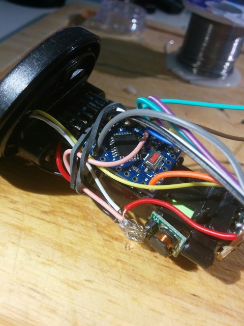
Here you can see the boost converter and the Arduino pro mini.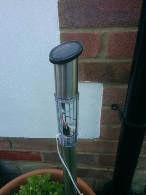
Here you can see the finished product in its natural environment. The RF radio sits in the plastic area, as I figured the metal collar at the top (where the arduino + battery sits) would have blocked/reduced the RF transmission.Code to follow.
-
I meant to mention that the wires coming out of the bottom are the wires that go to the soil moisture probes.
Here's the code in case anyone else would like it:
// Updated to v2.0 of Mysensors

// Enable debug prints
#define MY_DEBUG
#define MY_RADIO_NRF24

#include <MySensors.h>
#include <SPI.h>

#define round(x) ((x)>=0?(long)((x)+0.5):(long)((x)-0.5))
#define N_ELEMENTS(array) (sizeof(array)/sizeof((array)[0]))

#define CHILD_ID_MOISTURE 0
#define CHILD_ID_BATTERY 1
#define SLEEP_TIME 10000 // Sleep time between reads (in milliseconds), was 10000
#define THRESHOLD 1.1 // Only make a new reading with reverse polarity if the change is larger than 10%.
#define STABILIZATION_TIME 1000 // Let the sensor stabilize before reading default BOD settings
const int SENSOR_ANALOG_PINS[] = {A4, A5}; // Sensor is connected to these two pins. Avoid A3 if using ATSHA204. A6 and A7 cannot be used because they don't have pullups.

// MySensor gw;   //removed for v2.0
MyMessage msg(CHILD_ID_MOISTURE, V_HUM);
MyMessage voltage_msg(CHILD_ID_BATTERY, V_VOLTAGE);
long oldvoltage = 0;
byte direction = 0;
int oldMoistureLevel = -1;
float batteryPcnt;
float batteryVolt;
int LED = 5;

void setup()
{
  pinMode(LED, OUTPUT);
  digitalWrite(LED, HIGH);
  delay(200);
  digitalWrite(LED, LOW);
  delay(200);
  digitalWrite(LED, HIGH);
  delay(200);
  digitalWrite(LED, LOW);

  //  gw.begin(); //Removed for v2.0
  for (int i = 0; i < N_ELEMENTS(SENSOR_ANALOG_PINS); i++) {
    pinMode(SENSOR_ANALOG_PINS[i], OUTPUT);
    digitalWrite(SENSOR_ANALOG_PINS[i], LOW);
  }
}

void presentation(){  //created for v2.0
  sendSketchInfo("Plant moisture w solar", "1.0");
  present(CHILD_ID_MOISTURE, S_HUM);
  delay(250);
  present(CHILD_ID_BATTERY, S_MULTIMETER);
}


void loop()
{
  int moistureLevel = readMoisture();

  // Send rolling average of 2 samples to get rid of the "ripple" produced by different resistance in the internal pull-up resistors
  // See http://forum.mysensors.org/topic/2147/office-plant-monitoring/55 for more information
  if (oldMoistureLevel == -1) { // First reading, save current value as old
    oldMoistureLevel = moistureLevel;
  }
  if (moistureLevel > (oldMoistureLevel * THRESHOLD) || moistureLevel < (oldMoistureLevel / THRESHOLD)) {
    // The change was large, so it was probably not caused by the difference in internal pull-ups.
    // Measure again, this time with reversed polarity.
    moistureLevel = readMoisture();
  }
  send(msg.set((moistureLevel + oldMoistureLevel) / 2.0 / 10.23, 1));
  oldMoistureLevel = moistureLevel;

  int sensorValue = analogRead(A0);
  Serial.print("--Sensor value:");Serial.println(sensorValue);
  float voltage=sensorValue*(3.3/1023);
  Serial.print("--Voltage:");Serial.println(voltage);
  batteryPcnt = (sensorValue - 248) * 0.72;
  Serial.print("--Battery %:");Serial.println(batteryPcnt);
  batteryVolt = voltage;
  sendBatteryLevel(batteryPcnt);
  resend((voltage_msg.set(batteryVolt, 3)), 10);
  //send(voltage_msg.set(batteryVolt), 3);

  //flash led to indicate send
  digitalWrite(LED, HIGH);
  delay(200);
  digitalWrite(LED, LOW);

  sleep(SLEEP_TIME);
}

void resend(MyMessage &msg, int repeats)
{
  int repeat = 1;
  int repeatdelay = 0;
  boolean sendOK = false;

  send(msg);
/*
  while ((sendOK == false) and (repeat < repeats)) {
    if (send(msg)) {
      sendOK = true;
    } else {
      sendOK = false;
      Serial.print("Error ");
      Serial.println(repeat);
      repeatdelay += 500;
    } repeat++; delay(repeatdelay);
  }*/
}


int readMoisture() {
  pinMode(SENSOR_ANALOG_PINS[direction], INPUT_PULLUP); // Power on the sensor
  analogRead(SENSOR_ANALOG_PINS[direction]);// Read once to let the ADC capacitor start charging
  sleep(STABILIZATION_TIME);
  int moistureLevel = (1023 - analogRead(SENSOR_ANALOG_PINS[direction]));

  // Turn off the sensor to conserve battery and minimize corrosion
  pinMode(SENSOR_ANALOG_PINS[direction], OUTPUT);
  digitalWrite(SENSOR_ANALOG_PINS[direction], LOW);

  direction = (direction + 1) % 2; // Make direction alternate between 0 and 1 to reverse polarity which reduces corrosion
  return moistureLevel;
}
My thanks to flopp for the cool idea and to everyone else on the thread for the contributions.
-
Interesting project. To what degree, if any, has corrosion been a problem after you switched to soldered connections? Obviously the operating environment (near the ground outdoors) can be intrinsically humid.
Also, can someone please post a larger photo of how the sensor is attached at the base? The area of interest on the photo provided is miniscule, and it's too grainy if I try to enlarge it to a better size:

Hello! It looks like you're interested in this conversation, but you don't have an account yet.
Getting fed up of having to scroll through the same posts each visit? When you register for an account, you'll always come back to exactly where you were before, and choose to be notified of new replies (either via email, or push notification). You'll also be able to save bookmarks and upvote posts to show your appreciation to other community members.
With your input, this post could be even better 💗
Register Login