
MYSBootloader 1.3.0-beta.3
-
-
@Werwolfx As soon as the bootloader takes over, in your case after the reboot request (1), but before the MYS lib 2.1.0 init message (2):
(1) 14.01.2017 11:38:03 TX  4;0;3;0;13;0
(2) 14.01.2017 11:38:09 RX  4;255;0;0;17;2.1.0
it will send a I_FIRMWARE_CONFIG_REQUEST message to inform the controller about the currently loaded FW and request a new FW.
looks like this:
4;255;4;0;0;BE0001003003D8490102This is missing in your case, therefore I'm wondering if you have incompatible radio settings. Please post your GW sketch and upload your MYSBootloader.hex file for further troubleshooting.
-
@Werwolfx As soon as the bootloader takes over, in your case after the reboot request (1), but before the MYS lib 2.1.0 init message (2):
(1) 14.01.2017 11:38:03 TX  4;0;3;0;13;0
(2) 14.01.2017 11:38:09 RX  4;255;0;0;17;2.1.0
it will send a I_FIRMWARE_CONFIG_REQUEST message to inform the controller about the currently loaded FW and request a new FW.
looks like this:
4;255;4;0;0;BE0001003003D8490102This is missing in your case, therefore I'm wondering if you have incompatible radio settings. Please post your GW sketch and upload your MYSBootloader.hex file for further troubleshooting.
@tekka GW on esp8266 (default sketch) + NRF24L01+
on GW/** * The MySensors Arduino library handles the wireless radio link and protocol * between your home built sensors/actuators and HA controller of choice. * The sensors forms a self healing radio network with optional repeaters. Each * repeater and gateway builds a routing tables in EEPROM which keeps track of the * network topology allowing messages to be routed to nodes. * * Created by Henrik Ekblad <henrik.ekblad@mysensors.org> * Copyright (C) 2013-2015 Sensnology AB * Full contributor list: https://github.com/mysensors/Arduino/graphs/contributors * * Documentation: http://www.mysensors.org * Support Forum: http://forum.mysensors.org * * This program is free software; you can redistribute it and/or * modify it under the terms of the GNU General Public License * version 2 as published by the Free Software Foundation. * ******************************* * * REVISION HISTORY * Version 1.0 - Henrik EKblad * Contribution by a-lurker and Anticimex, * Contribution by Norbert Truchsess <norbert.truchsess@t-online.de> * Contribution by Ivo Pullens (ESP8266 support) * * DESCRIPTION * The EthernetGateway sends data received from sensors to the WiFi link. * The gateway also accepts input on ethernet interface, which is then sent out to the radio network. * * VERA CONFIGURATION: * Enter "ip-number:port" in the ip-field of the Arduino GW device. This will temporarily override any serial configuration for the Vera plugin. * E.g. If you want to use the defualt values in this sketch enter: 192.168.178.66:5003 * * LED purposes: * - To use the feature, uncomment any of the MY_DEFAULT_xx_LED_PINs in your sketch, only the LEDs that is defined is used. * - RX (green) - blink fast on radio message recieved. In inclusion mode will blink fast only on presentation recieved * - TX (yellow) - blink fast on radio message transmitted. In inclusion mode will blink slowly * - ERR (red) - fast blink on error during transmission error or recieve crc error * * See http://www.mysensors.org/build/esp8266_gateway for wiring instructions. * nRF24L01+ ESP8266 * VCC VCC * CE GPIO4 * CSN/CS GPIO15 * SCK GPIO14 * MISO GPIO12 * MOSI GPIO13 * GND GND * * Not all ESP8266 modules have all pins available on their external interface. * This code has been tested on an ESP-12 module. * The ESP8266 requires a certain pin configuration to download code, and another one to run code: * - Connect REST (reset) via 10K pullup resistor to VCC, and via switch to GND ('reset switch') * - Connect GPIO15 via 10K pulldown resistor to GND * - Connect CH_PD via 10K resistor to VCC * - Connect GPIO2 via 10K resistor to VCC * - Connect GPIO0 via 10K resistor to VCC, and via switch to GND ('bootload switch') * * Inclusion mode button: * - Connect GPIO5 via switch to GND ('inclusion switch') * * Hardware SHA204 signing is currently not supported! * * Make sure to fill in your ssid and WiFi password below for ssid & pass. */ // Enable debug prints to serial monitor #define MY_DEBUG // Use a bit lower baudrate for serial prints on ESP8266 than default in MyConfig.h #define MY_BAUD_RATE 115200 // Enables and select radio type (if attached) #define MY_RADIO_NRF24 //#define MY_RADIO_RFM69 #define MY_GATEWAY_ESP8266 #define MY_ESP8266_SSID "WiFI" #define MY_ESP8266_PASSWORD "password[0_1484386469111_MYSBootloader.hex](/uploads/files/1484386469171-mysbootloader.hex) " // Enable UDP communication //#define MY_USE_UDP // Set the hostname for the WiFi Client. This is the hostname // it will pass to the DHCP server if not static. // #define MY_ESP8266_HOSTNAME "sensor-gateway" // Enable MY_IP_ADDRESS here if you want a static ip address (no DHCP) //#define MY_IP_ADDRESS 192,168,178,87 // If using static ip you need to define Gateway and Subnet address as well //#define MY_IP_GATEWAY_ADDRESS 192,168,178,1 //#define MY_IP_SUBNET_ADDRESS 255,255,255,0 // The port to keep open on node server mode #define MY_PORT 5003 // How many clients should be able to connect to this gateway (default 1) #define MY_GATEWAY_MAX_CLIENTS 2 // Controller ip address. Enables client mode (default is "server" mode). // Also enable this if MY_USE_UDP is used and you want sensor data sent somewhere. //#define MY_CONTROLLER_IP_ADDRESS 192, 168, 178, 68 // Enable inclusion mode #define MY_INCLUSION_MODE_FEATURE // Enable Inclusion mode button on gateway // #define MY_INCLUSION_BUTTON_FEATURE // Set inclusion mode duration (in seconds) #define MY_INCLUSION_MODE_DURATION 60 // Digital pin used for inclusion mode button #define MY_INCLUSION_MODE_BUTTON_PIN 3 // Set blinking period // #define MY_DEFAULT_LED_BLINK_PERIOD 300 // Flash leds on rx/tx/err // Led pins used if blinking feature is enabled above #define MY_DEFAULT_ERR_LED_PIN 16 // Error led pin #define MY_DEFAULT_RX_LED_PIN 16 // Receive led pin #define MY_DEFAULT_TX_LED_PIN 16 // the PCB, on board LED #if defined(MY_USE_UDP) #include <WiFiUdp.h> #endif #include <ESP8266WiFi.h> #include <MySensors.h> void setup() { } void presentation() { // Present locally attached sensors here } void loop() { // Send locally attached sensors data here }In MYSController on mudule i click INFO
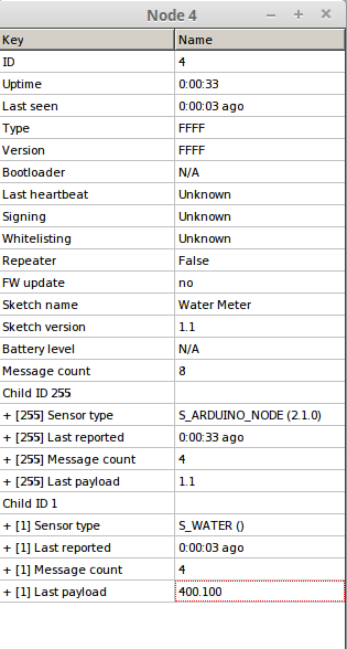
FW Update = no
Bootloader = N/Amay be problem in the Bootloader.hex?
-
@tekka GW on esp8266 (default sketch) + NRF24L01+
on GW/** * The MySensors Arduino library handles the wireless radio link and protocol * between your home built sensors/actuators and HA controller of choice. * The sensors forms a self healing radio network with optional repeaters. Each * repeater and gateway builds a routing tables in EEPROM which keeps track of the * network topology allowing messages to be routed to nodes. * * Created by Henrik Ekblad <henrik.ekblad@mysensors.org> * Copyright (C) 2013-2015 Sensnology AB * Full contributor list: https://github.com/mysensors/Arduino/graphs/contributors * * Documentation: http://www.mysensors.org * Support Forum: http://forum.mysensors.org * * This program is free software; you can redistribute it and/or * modify it under the terms of the GNU General Public License * version 2 as published by the Free Software Foundation. * ******************************* * * REVISION HISTORY * Version 1.0 - Henrik EKblad * Contribution by a-lurker and Anticimex, * Contribution by Norbert Truchsess <norbert.truchsess@t-online.de> * Contribution by Ivo Pullens (ESP8266 support) * * DESCRIPTION * The EthernetGateway sends data received from sensors to the WiFi link. * The gateway also accepts input on ethernet interface, which is then sent out to the radio network. * * VERA CONFIGURATION: * Enter "ip-number:port" in the ip-field of the Arduino GW device. This will temporarily override any serial configuration for the Vera plugin. * E.g. If you want to use the defualt values in this sketch enter: 192.168.178.66:5003 * * LED purposes: * - To use the feature, uncomment any of the MY_DEFAULT_xx_LED_PINs in your sketch, only the LEDs that is defined is used. * - RX (green) - blink fast on radio message recieved. In inclusion mode will blink fast only on presentation recieved * - TX (yellow) - blink fast on radio message transmitted. In inclusion mode will blink slowly * - ERR (red) - fast blink on error during transmission error or recieve crc error * * See http://www.mysensors.org/build/esp8266_gateway for wiring instructions. * nRF24L01+ ESP8266 * VCC VCC * CE GPIO4 * CSN/CS GPIO15 * SCK GPIO14 * MISO GPIO12 * MOSI GPIO13 * GND GND * * Not all ESP8266 modules have all pins available on their external interface. * This code has been tested on an ESP-12 module. * The ESP8266 requires a certain pin configuration to download code, and another one to run code: * - Connect REST (reset) via 10K pullup resistor to VCC, and via switch to GND ('reset switch') * - Connect GPIO15 via 10K pulldown resistor to GND * - Connect CH_PD via 10K resistor to VCC * - Connect GPIO2 via 10K resistor to VCC * - Connect GPIO0 via 10K resistor to VCC, and via switch to GND ('bootload switch') * * Inclusion mode button: * - Connect GPIO5 via switch to GND ('inclusion switch') * * Hardware SHA204 signing is currently not supported! * * Make sure to fill in your ssid and WiFi password below for ssid & pass. */ // Enable debug prints to serial monitor #define MY_DEBUG // Use a bit lower baudrate for serial prints on ESP8266 than default in MyConfig.h #define MY_BAUD_RATE 115200 // Enables and select radio type (if attached) #define MY_RADIO_NRF24 //#define MY_RADIO_RFM69 #define MY_GATEWAY_ESP8266 #define MY_ESP8266_SSID "WiFI" #define MY_ESP8266_PASSWORD "password[0_1484386469111_MYSBootloader.hex](/uploads/files/1484386469171-mysbootloader.hex) " // Enable UDP communication //#define MY_USE_UDP // Set the hostname for the WiFi Client. This is the hostname // it will pass to the DHCP server if not static. // #define MY_ESP8266_HOSTNAME "sensor-gateway" // Enable MY_IP_ADDRESS here if you want a static ip address (no DHCP) //#define MY_IP_ADDRESS 192,168,178,87 // If using static ip you need to define Gateway and Subnet address as well //#define MY_IP_GATEWAY_ADDRESS 192,168,178,1 //#define MY_IP_SUBNET_ADDRESS 255,255,255,0 // The port to keep open on node server mode #define MY_PORT 5003 // How many clients should be able to connect to this gateway (default 1) #define MY_GATEWAY_MAX_CLIENTS 2 // Controller ip address. Enables client mode (default is "server" mode). // Also enable this if MY_USE_UDP is used and you want sensor data sent somewhere. //#define MY_CONTROLLER_IP_ADDRESS 192, 168, 178, 68 // Enable inclusion mode #define MY_INCLUSION_MODE_FEATURE // Enable Inclusion mode button on gateway // #define MY_INCLUSION_BUTTON_FEATURE // Set inclusion mode duration (in seconds) #define MY_INCLUSION_MODE_DURATION 60 // Digital pin used for inclusion mode button #define MY_INCLUSION_MODE_BUTTON_PIN 3 // Set blinking period // #define MY_DEFAULT_LED_BLINK_PERIOD 300 // Flash leds on rx/tx/err // Led pins used if blinking feature is enabled above #define MY_DEFAULT_ERR_LED_PIN 16 // Error led pin #define MY_DEFAULT_RX_LED_PIN 16 // Receive led pin #define MY_DEFAULT_TX_LED_PIN 16 // the PCB, on board LED #if defined(MY_USE_UDP) #include <WiFiUdp.h> #endif #include <ESP8266WiFi.h> #include <MySensors.h> void setup() { } void presentation() { // Present locally attached sensors here } void loop() { // Send locally attached sensors data here }In MYSController on mudule i click INFO
FW Update = no
Bootloader = N/Amay be problem in the Bootloader.hex?
-
@tekka said:
@Werwolfx Please also update the bootloader file.
I'll update more than once, but there is no effect.
avrdude writes that everything is OK
I do not know what to do = (avrdude: AVR device initialized and ready to accept instructions Reading | ################################################## | 100% 0.00s avrdude: Device signature = 0x1e950f (probably m328p) avrdude: NOTE: "flash" memory has been specified, an erase cycle will be performed To disable this feature, specify the -D option. avrdude: erasing chip avrdude: auto set sck period (because given equals null) avrdude: warning: cannot set sck period. please check for usbasp firmware update. avrdude: reading input file "/media/werwolfx/SSDData/arduino-1.8.0/hardware/arduino/avr/bootloaders/MySensors/MYSBootloader.hex" avrdude: writing flash (32762 bytes): Writing | ################################################## | 100% 0.00s avrdude: 32762 bytes of flash written avrdude: verifying flash memory against /media/werwolfx/SSDData/arduino-1.8.0/hardware/arduino/avr/bootloaders/MySensors/MYSBootloader.hex: avrdude: load data flash data from input file /media/werwolfx/SSDData/arduino-1.8.0/hardware/arduino/avr/bootloaders/MySensors/MYSBootloader.hex: avrdude: input file /media/werwolfx/SSDData/arduino-1.8.0/hardware/arduino/avr/bootloaders/MySensors/MYSBootloader.hex contains 32762 bytes avrdude: reading on-chip flash data: Reading | ################################################## | 100% 0.00s avrdude: verifying ... avrdude: 32762 bytes of flash verified avrdude: reading input file "0x0F" avrdude: writing lock (1 bytes): Writing | ################################################## | 100% 0.01s avrdude: 1 bytes of lock written avrdude: verifying lock memory against 0x0F: avrdude: load data lock data from input file 0x0F: avrdude: input file 0x0F contains 1 bytes avrdude: reading on-chip lock data: Reading | ################################################## | 100% 0.00s avrdude: verifying ... avrdude: 1 bytes of lock verified avrdude done. Thank you. -
@tekka said:
@Werwolfx Please also update the bootloader file.
I'll update more than once, but there is no effect.
avrdude writes that everything is OK
I do not know what to do = (avrdude: AVR device initialized and ready to accept instructions Reading | ################################################## | 100% 0.00s avrdude: Device signature = 0x1e950f (probably m328p) avrdude: NOTE: "flash" memory has been specified, an erase cycle will be performed To disable this feature, specify the -D option. avrdude: erasing chip avrdude: auto set sck period (because given equals null) avrdude: warning: cannot set sck period. please check for usbasp firmware update. avrdude: reading input file "/media/werwolfx/SSDData/arduino-1.8.0/hardware/arduino/avr/bootloaders/MySensors/MYSBootloader.hex" avrdude: writing flash (32762 bytes): Writing | ################################################## | 100% 0.00s avrdude: 32762 bytes of flash written avrdude: verifying flash memory against /media/werwolfx/SSDData/arduino-1.8.0/hardware/arduino/avr/bootloaders/MySensors/MYSBootloader.hex: avrdude: load data flash data from input file /media/werwolfx/SSDData/arduino-1.8.0/hardware/arduino/avr/bootloaders/MySensors/MYSBootloader.hex: avrdude: input file /media/werwolfx/SSDData/arduino-1.8.0/hardware/arduino/avr/bootloaders/MySensors/MYSBootloader.hex contains 32762 bytes avrdude: reading on-chip flash data: Reading | ################################################## | 100% 0.00s avrdude: verifying ... avrdude: 32762 bytes of flash verified avrdude: reading input file "0x0F" avrdude: writing lock (1 bytes): Writing | ################################################## | 100% 0.01s avrdude: 1 bytes of lock written avrdude: verifying lock memory against 0x0F: avrdude: load data lock data from input file 0x0F: avrdude: input file 0x0F contains 1 bytes avrdude: reading on-chip lock data: Reading | ################################################## | 100% 0.00s avrdude: verifying ... avrdude: 1 bytes of lock verified avrdude done. Thank you. -
@tekka If i ENABLE #define MY_OTA_FIRMWARE_FEATURE
i see ST_FIRMWARE_CONFIG_REQUEST in MYSCONTROLLER logs!!!
if i DISABLE //#define MY_OTA_FIRMWARE_FEATURE msg not in logi not have external flash/
402	14.01.2017 21:29:28	TX	4 - Water Meter	N/A	C_INTERNAL	NO	I_REBOOT	0
403	14.01.2017 21:29:28	RX	4	1	C_REQ	NO	V_VAR1
408	14.01.2017 21:29:34	RX	4	INTERNAL	C_STREAM	NO	ST_FIRMWARE_CONFIG_REQUEST	FFFFFFFF48044E100300
409	14.01.2017 21:29:34	TX	4	N/A	C_STREAM	NO	ST_FIRMWARE_CONFIG_RESPONSE	0A0001005000D446
410	14.01.2017 21:29:34	RX	4	INTERNAL	C_PRESENTATION	NO	S_ARDUINO_NODE	2.1.0
411	14.01.2017 21:29:34	RX	4	INTERNAL	C_INTERNAL	NO	I_CONFIG	0
412	14.01.2017 21:29:34	TX	4	INTERNAL	C_INTERNAL	NO	I_CONFIG	M
414	14.01.2017 21:29:34	RX	4 - Water Meter	INTERNAL	C_INTERNAL	NO	I_SKETCH_NAME	Water Meter
417	14.01.2017 21:29:34	RX	4 - Water Meter	INTERNAL	C_INTERNAL	NO	I_SKETCH_VERSION	1.1
419	14.01.2017 21:29:34	RX	4 - Water Meter	1 - S_WATER	C_PRESENTATION	NO	S_WATER
i load this HEX
load from Arduino IDE 1.8.0
0_1484418874223_MYSBootloader.hexboard.txt
proMYSBL.bootloader.tool=avrdude
proMYSBL.bootloader.low_fuses=0xFF
proMYSBL.bootloader.high_fuses=0xDA
proMYSBL.bootloader.extended_fuses=0xFE
proMYSBL.bootloader.unlock_bits=0x3F
proMYSBL.bootloader.lock_bits=0x0F
proMYSBL.bootloader.file=MySensors/MYSBootloader.hex -
@tekka If i ENABLE #define MY_OTA_FIRMWARE_FEATURE
i see ST_FIRMWARE_CONFIG_REQUEST in MYSCONTROLLER logs!!!
if i DISABLE //#define MY_OTA_FIRMWARE_FEATURE msg not in logi not have external flash/
402	14.01.2017 21:29:28	TX	4 - Water Meter	N/A	C_INTERNAL	NO	I_REBOOT	0
403	14.01.2017 21:29:28	RX	4	1	C_REQ	NO	V_VAR1
408	14.01.2017 21:29:34	RX	4	INTERNAL	C_STREAM	NO	ST_FIRMWARE_CONFIG_REQUEST	FFFFFFFF48044E100300
409	14.01.2017 21:29:34	TX	4	N/A	C_STREAM	NO	ST_FIRMWARE_CONFIG_RESPONSE	0A0001005000D446
410	14.01.2017 21:29:34	RX	4	INTERNAL	C_PRESENTATION	NO	S_ARDUINO_NODE	2.1.0
411	14.01.2017 21:29:34	RX	4	INTERNAL	C_INTERNAL	NO	I_CONFIG	0
412	14.01.2017 21:29:34	TX	4	INTERNAL	C_INTERNAL	NO	I_CONFIG	M
414	14.01.2017 21:29:34	RX	4 - Water Meter	INTERNAL	C_INTERNAL	NO	I_SKETCH_NAME	Water Meter
417	14.01.2017 21:29:34	RX	4 - Water Meter	INTERNAL	C_INTERNAL	NO	I_SKETCH_VERSION	1.1
419	14.01.2017 21:29:34	RX	4 - Water Meter	1 - S_WATER	C_PRESENTATION	NO	S_WATER
i load this HEX
load from Arduino IDE 1.8.0
0_1484418874223_MYSBootloader.hexboard.txt
proMYSBL.bootloader.tool=avrdude
proMYSBL.bootloader.low_fuses=0xFF
proMYSBL.bootloader.high_fuses=0xDA
proMYSBL.bootloader.extended_fuses=0xFE
proMYSBL.bootloader.unlock_bits=0x3F
proMYSBL.bootloader.lock_bits=0x0F
proMYSBL.bootloader.file=MySensors/MYSBootloader.hex -
@tekka am I correct in thinking the HEX found on Github can be used with all Arduino's? I noticed my old folder has one hex for 16, 8 and 1Mhz?
I'm using this board.txt
menu.cpu=Processor ############################################################## MYSBL13.name=MYS Bootloader - atmega328p MYSBL13.upload.tool=arduino:avrdude MYSBL13.upload.protocol=arduino MYSBL13.upload.maximum_size=30720 MYSBL13.upload.maximum_data_size=2048 MYSBL13.bootloader.tool=arduino:avrdude MYSBL13.bootloader.unlock_bits=0x3F MYSBL13.bootloader.lock_bits=0x0F MYSBL13.build.mcu=atmega328p MYSBL13.build.board=AVR_PRO MYSBL13.build.core=arduino:arduino MYSBL13.build.variant=arduino:standard ## ------------------------------------------------- MYSBL13.menu.cpu.16MHzatmega328=ATmega328 16MHz (XTAL, BOD1V8) MYSBL13.menu.cpu.16MHzatmega328.upload.speed=115200 MYSBL13.menu.cpu.16MHzatmega328.bootloader.low_fuses=0xFF MYSBL13.menu.cpu.16MHzatmega328.bootloader.high_fuses=0xDA MYSBL13.menu.cpu.16MHzatmega328.bootloader.extended_fuses=0x06 MYSBL13.menu.cpu.16MHzatmega328.bootloader.file=MYSBootloader/MYSBootloader.hex MYSBL13.menu.cpu.16MHzatmega328.build.f_cpu=16000000L MYSBL13.menu.cpu.8MHzatmega328=ATmega328 8MHz (RC, BOD1V8) MYSBL13.menu.cpu.8MHzatmega328.upload.speed=38400 MYSBL13.menu.cpu.8MHzatmega328.bootloader.low_fuses=0xE2 MYSBL13.menu.cpu.8MHzatmega328.bootloader.high_fuses=0xDA MYSBL13.menu.cpu.8MHzatmega328.bootloader.extended_fuses=0x06 MYSBL13.menu.cpu.8MHzatmega328.bootloader.file=MYSBootloader/MYSBootloader.hex MYSBL13.menu.cpu.8MHzatmega328.build.f_cpu=8000000L MYSBL13.menu.cpu.1MHzatmega328=ATmega328 1MHz (RC/8, BOD1V8) MYSBL13.menu.cpu.1MHzatmega328.upload.speed=9600 MYSBL13.menu.cpu.1MHzatmega328.bootloader.low_fuses=0x62 MYSBL13.menu.cpu.1MHzatmega328.bootloader.high_fuses=0xDA MYSBL13.menu.cpu.1MHzatmega328.bootloader.extended_fuses=0x06 MYSBL13.menu.cpu.1MHzatmega328.bootloader.file=MYSBootloader/MYSBootloader.hex MYSBL13.menu.cpu.1MHzatmega328.build.f_cpu=1000000L``` -
I guess not... The old hex for 8Mhz works, but the one from this thread does not... :(
I'm trying to upload this to my Pro Mini, does anyone have an 8Mhz that works?
-
@tekka I've noticed some odd things with my nodes when running the bootloader.
To test I uploaded a simple count time sketch. When running the MYS bootloader the timer resets every 10 seconds, see:
Time: 999
Time: 2000
Time: 3000
Time: 4001
Time: 5001
Time: 6002
Time: 7004
Time: 8003
Time: 9005
Time: 0
Time: 999
Time: 2000
Time: 3000
Time: 4001
Time: 5001
Time: 6002
Time: 7004
Time: 8003
Time: 9005
Time: 0
Using the stock Pro Mim 8Mhz 3.3v bootloader it works fine, any ideas?
Perhaps this is because I'm testing using a non-MySensors sketch? -
@tekka I've noticed some odd things with my nodes when running the bootloader.
To test I uploaded a simple count time sketch. When running the MYS bootloader the timer resets every 10 seconds, see:
Time: 999
Time: 2000
Time: 3000
Time: 4001
Time: 5001
Time: 6002
Time: 7004
Time: 8003
Time: 9005
Time: 0
Time: 999
Time: 2000
Time: 3000
Time: 4001
Time: 5001
Time: 6002
Time: 7004
Time: 8003
Time: 9005
Time: 0
Using the stock Pro Mim 8Mhz 3.3v bootloader it works fine, any ideas?
Perhaps this is because I'm testing using a non-MySensors sketch? -
-
-
@tekka, I'm trying to compile the HEX using OSX. I have installed avr-gcc with homebrew but I get
rm *.o
rm: *.o: No such file or directory
make: [clean] Error 1 (ignored)
rm *.elf
rm: *.elf: No such file or directory
make: [clean] Error 1 (ignored)
rm *.hex
rm: *.hex: No such file or directory
make: [clean] Error 1 (ignored)
"avr-gcc" -funsigned-char -funsigned-bitfields -DF_CPU=16000000L -Os -ffunction-sections -fdata-sections -fpack-struct -fshort-enums -mrelax -Wall -Wextra -Wundef -pedantic -mmcu=atmega328p -c -std=gnu99 -MD -MP -MF "MYSBootloader.d" -MT"MYSBootloader.d" -MT"MYSBootloader.o" -I MYSBootloader.c -o MYSBootloader.o
avr-gcc: fatal error: no input files
compilation terminated.
make: *** [MYSBootloader.o] Error 1When issueing the Make command, can you help, any suggestions?
-
@tekka, I'm trying to compile the HEX using OSX. I have installed avr-gcc with homebrew but I get
rm *.o
rm: *.o: No such file or directory
make: [clean] Error 1 (ignored)
rm *.elf
rm: *.elf: No such file or directory
make: [clean] Error 1 (ignored)
rm *.hex
rm: *.hex: No such file or directory
make: [clean] Error 1 (ignored)
"avr-gcc" -funsigned-char -funsigned-bitfields -DF_CPU=16000000L -Os -ffunction-sections -fdata-sections -fpack-struct -fshort-enums -mrelax -Wall -Wextra -Wundef -pedantic -mmcu=atmega328p -c -std=gnu99 -MD -MP -MF "MYSBootloader.d" -MT"MYSBootloader.d" -MT"MYSBootloader.o" -I MYSBootloader.c -o MYSBootloader.o
avr-gcc: fatal error: no input files
compilation terminated.
make: *** [MYSBootloader.o] Error 1When issueing the Make command, can you help, any suggestions?
-
@tekka, started a windows VM, run via MinGW and got this when running makefile, does it look okay?
C:\MySensorsBootloaderRF24-development>mingw32-make.exe rm *.o process_begin: CreateProcess(NULL, rm *.o, ...) failed. make (e=2): The system cannot find the file specified. Makefile:40: recipe for target 'clean' failed mingw32-make.exe: [clean] Error 2 (ignored) rm *.elf process_begin: CreateProcess(NULL, rm *.elf, ...) failed. make (e=2): The system cannot find the file specified. Makefile:40: recipe for target 'clean' failed mingw32-make.exe: [clean] Error 2 (ignored) rm *.hex process_begin: CreateProcess(NULL, rm *.hex, ...) failed. make (e=2): The system cannot find the file specified. Makefile:40: recipe for target 'clean' failed mingw32-make.exe: [clean] Error 2 (ignored) "C:/Arduino/hardware/tools/avr/bin/avr-gcc" -funsigned-char -funsigned-bitfields -DF_CPU=16000000L -Os -ffunction-sections -fdata-sections -fpack-struct -fshort -enums -mrelax -Wall -Wextra -Wundef -pedantic -mmcu=atmega328p -c -std=gnu99 -M D -MP -MF "MYSBootloader.d" -MT"MYSBootloader.d" -MT"MYSBootloader.o" -IC:/Ardu ino/hardware/tools/avr/avr/include/avr MYSBootloader.c -o MYSBootloader.o In file included from Core.h:40:0, from MYSBootloader.c:69: HW.h:51:2: warning: #warning is a GCC extension #warning BAUD_RATE error greater than 2% ^ HW.h:51:2: warning: #warning BAUD_RATE error greater than 2% [-Wcpp] In file included from Core.h:42:0, from MYSBootloader.c:69: MyMessage.h:292:3: warning: ISO C99 doesn't support unnamed structs/unions [-Wpe dantic] }; ^ "C:/Arduino/hardware/tools/avr/bin/avr-gcc" -nostartfiles -Wl,-s -Wl,-static -Wl ,-Map=".map" -Wl,--start-group -Wl,--end-group -Wl,--gc-sections -mrelax -Wl,-se ction-start=.text=0x7800 -mmcu=atmega328p -o MYSBootloader.elf MYSBootloader.o -lm "C:/Arduino/hardware/tools/avr/bin/avr-objcopy" -O ihex -R .eeprom MYSBootloader .elf MYSBootloader.hex "C:/Arduino/hardware/tools/avr/bin/avr-size" MYSBootloader.elf text data bss dec hex filename 2036 6 72 2114 842 MYSBootloader.elf -
@tekka Just wanted to check if the above log looks okay, currently rolling the bootloader out to 14 nodes (painful process!) and wanted to check if it looks okay before I do.
I'm also using this board.txt, I made a separate entry for my Uno's, do they all look okay? I basically used the fuses from the standard Arduino boards.txt with the change of 0x05 to 0x06 for the BOD? I noticed in the makefile that you can specify the fuses, do I need to compile a bootloader for each device with the exact fuses, or will one bootloader for 16 / 8 / 1Mhz suffice?
Thank you very much in advance, the bootloader is amazing work.
menu.cpu=Processor ############################################################## pro.name=MySensors Bootloader for Pro Mini pro.upload.tool=arduino:avrdude pro.upload.protocol=arduino pro.upload.maximum_size=30720 pro.upload.maximum_data_size=2048 pro.bootloader.tool=arduino:avrdude pro.bootloader.unlock_bits=0x3F pro.bootloader.lock_bits=0x0F pro.build.mcu=atmega328p pro.build.board=AVR_PRO pro.build.core=arduino:arduino pro.build.variant=arduino:standard ## Arduino with MYSBootloader Beta 2 ## ------------------------------------------------- ## pro.menu.cpu.16MHzatmega328=ATmega328 16MHz (XTAL, BOD1V8) 1.3 Beta 2 ## pro.menu.cpu.16MHzatmega328.upload.speed=115200 ## pro.menu.cpu.16MHzatmega328.bootloader.low_fuses=0xFF ## pro.menu.cpu.16MHzatmega328.bootloader.high_fuses=0xDA ## pro.menu.cpu.16MHzatmega328.bootloader.extended_fuses=0x06 ## pro.menu.cpu.16MHzatmega328.bootloader.file=MYSBootloader/MYSBootloader_B2_16Mhz.hex ## pro.menu.cpu.16MHzatmega328.build.f_cpu=16000000L ## pro.menu.cpu.8MHzatmega328=ATmega328 8MHz (RC, BOD1V8) 1.3 Beta 2 ## pro.menu.cpu.8MHzatmega328.upload.speed=38400 ## pro.menu.cpu.8MHzatmega328.bootloader.low_fuses=0xE2 ## pro.menu.cpu.8MHzatmega328.bootloader.high_fuses=0xDA ## pro.menu.cpu.8MHzatmega328.bootloader.extended_fuses=0x06 ## pro.menu.cpu.8MHzatmega328.bootloader.file=MYSBootloader/MYSBootloader_B2_8Mhz.hex ## pro.menu.cpu.8MHzatmega328.build.f_cpu=8000000L ## pro.menu.cpu.1MHzatmega328=ATmega328 1MHz (RC/8, BOD1V8) 1.3 Beta 2 ## pro.menu.cpu.1MHzatmega328.upload.speed=9600 ## pro.menu.cpu.1MHzatmega328.bootloader.low_fuses=0x62 ## pro.menu.cpu.1MHzatmega328.bootloader.high_fuses=0xDA ## pro.menu.cpu.1MHzatmega328.bootloader.extended_fuses=0x06 ## pro.menu.cpu.1MHzatmega328.bootloader.file=MYSBootloader/MYSBootloader_B2_1Mhz.hex ## pro.menu.cpu.1MHzatmega328.build.f_cpu=1000000L ## Arduino with MYSBootloader Beta 3 ## ------------------------------------------------- pro.menu.cpu.16MHzatmega328=ATmega328 16MHz (XTAL, BOD1V8) 1.3 Beta 3 pro.menu.cpu.16MHzatmega328.upload.speed=115200 pro.menu.cpu.16MHzatmega328.bootloader.low_fuses=0xFF pro.menu.cpu.16MHzatmega328.bootloader.high_fuses=0xDA pro.menu.cpu.16MHzatmega328.bootloader.extended_fuses=0x06 pro.menu.cpu.16MHzatmega328.bootloader.file=MYSBootloader/MYSBootloader_B3_16Mhz.hex pro.menu.cpu.16MHzatmega328.build.f_cpu=16000000L pro.menu.cpu.8MHzatmega328=ATmega328 8MHz (RC, BOD1V8) 1.3 Beta 3 pro.menu.cpu.8MHzatmega328.upload.speed=38400 pro.menu.cpu.8MHzatmega328.bootloader.low_fuses=0xFF pro.menu.cpu.8MHzatmega328.bootloader.high_fuses=0xDA pro.menu.cpu.8MHzatmega328.bootloader.extended_fuses=0x06 pro.menu.cpu.8MHzatmega328.bootloader.file=MYSBootloader/MYSBootloader_B3_8Mhz.hex pro.menu.cpu.8MHzatmega328.build.f_cpu=8000000L pro.menu.cpu.1MHzatmega328=ATmega328 1MHz (RC/8, BOD1V8) 1.3 Beta 3 pro.menu.cpu.1MHzatmega328.upload.speed=9600 pro.menu.cpu.1MHzatmega328.bootloader.low_fuses=0x62 pro.menu.cpu.1MHzatmega328.bootloader.high_fuses=0xDA pro.menu.cpu.1MHzatmega328.bootloader.extended_fuses=0x06 pro.menu.cpu.1MHzatmega328.bootloader.file=MYSBootloader/MYSBootloader_B3_1Mhz.hex pro.menu.cpu.1MHzatmega328.build.f_cpu=1000000L ############################################################## ############################################################## ############################################################## ############################################################## ############################################################## menu.cpu=Processor ############################################################## uno.name=MySensors Bootloader for Uno uno.upload.tool=arduino:avrdude uno.upload.protocol=arduino uno.upload.maximum_size=32256 uno.upload.maximum_data_size=2048 uno.bootloader.tool=arduino:avrdude uno.bootloader.unlock_bits=0x3F uno.bootloader.lock_bits=0x0F uno.build.mcu=atmega328p uno.build.board=AVR_UNO uno.build.core=arduino:arduino uno.build.variant=arduino:standard ## Arduino with MYSBootloader Beta 2 ## ------------------------------------------------- ## uno.menu.cpu.16MHzatmega328=ATmega328 16MHz (XTAL, BOD1V8) 1.3 Beta 2 ## uno.menu.cpu.16MHzatmega328.upload.speed=115200 ## uno.menu.cpu.16MHzatmega328.bootloader.low_fuses=0xFF ## uno.menu.cpu.16MHzatmega328.bootloader.high_fuses=0xDA ## uno.menu.cpu.16MHzatmega328.bootloader.extended_fuses=0x06 ## uno.menu.cpu.16MHzatmega328.bootloader.file=MYSBootloader/MYSBootloader_B2_16Mhz.hex ## uno.menu.cpu.16MHzatmega328.build.f_cpu=16000000L ## Arduino with MYSBootloader Beta 3 ## ------------------------------------------------- uno.menu.cpu.16MHzatmega328=ATmega328 16MHz (XTAL, BOD1V8) 1.3 Beta 3 uno.menu.cpu.16MHzatmega328.upload.speed=115200 uno.menu.cpu.16MHzatmega328.bootloader.low_fuses=0xFF uno.menu.cpu.16MHzatmega328.bootloader.high_fuses=0xDA uno.menu.cpu.16MHzatmega328.bootloader.extended_fuses=0x06 uno.menu.cpu.16MHzatmega328.bootloader.file=MYSBootloader/MYSBootloader_B3_16Mhz.hex uno.menu.cpu.16MHzatmega328.build.f_cpu=16000000L -
@tekka, started a windows VM, run via MinGW and got this when running makefile, does it look okay?
C:\MySensorsBootloaderRF24-development>mingw32-make.exe rm *.o process_begin: CreateProcess(NULL, rm *.o, ...) failed. make (e=2): The system cannot find the file specified. Makefile:40: recipe for target 'clean' failed mingw32-make.exe: [clean] Error 2 (ignored) rm *.elf process_begin: CreateProcess(NULL, rm *.elf, ...) failed. make (e=2): The system cannot find the file specified. Makefile:40: recipe for target 'clean' failed mingw32-make.exe: [clean] Error 2 (ignored) rm *.hex process_begin: CreateProcess(NULL, rm *.hex, ...) failed. make (e=2): The system cannot find the file specified. Makefile:40: recipe for target 'clean' failed mingw32-make.exe: [clean] Error 2 (ignored) "C:/Arduino/hardware/tools/avr/bin/avr-gcc" -funsigned-char -funsigned-bitfields -DF_CPU=16000000L -Os -ffunction-sections -fdata-sections -fpack-struct -fshort -enums -mrelax -Wall -Wextra -Wundef -pedantic -mmcu=atmega328p -c -std=gnu99 -M D -MP -MF "MYSBootloader.d" -MT"MYSBootloader.d" -MT"MYSBootloader.o" -IC:/Ardu ino/hardware/tools/avr/avr/include/avr MYSBootloader.c -o MYSBootloader.o In file included from Core.h:40:0, from MYSBootloader.c:69: HW.h:51:2: warning: #warning is a GCC extension #warning BAUD_RATE error greater than 2% ^ HW.h:51:2: warning: #warning BAUD_RATE error greater than 2% [-Wcpp] In file included from Core.h:42:0, from MYSBootloader.c:69: MyMessage.h:292:3: warning: ISO C99 doesn't support unnamed structs/unions [-Wpe dantic] }; ^ "C:/Arduino/hardware/tools/avr/bin/avr-gcc" -nostartfiles -Wl,-s -Wl,-static -Wl ,-Map=".map" -Wl,--start-group -Wl,--end-group -Wl,--gc-sections -mrelax -Wl,-se ction-start=.text=0x7800 -mmcu=atmega328p -o MYSBootloader.elf MYSBootloader.o -lm "C:/Arduino/hardware/tools/avr/bin/avr-objcopy" -O ihex -R .eeprom MYSBootloader .elf MYSBootloader.hex "C:/Arduino/hardware/tools/avr/bin/avr-size" MYSBootloader.elf text data bss dec hex filename 2036 6 72 2114 842 MYSBootloader.elf -
@Mark-Swift What changes did you make to the bootloader - the code size seems increased
@tekka None that I'm aware of? :(
I just changed the fuses in the makefile to match the ones in my boards.txt, not sure if that's required, can you take a look at my questions above, I really want to be sure I'm doing all of this right before deploying.
To recap with regards the bootloader.
- Installed Windows 7
- Installed mingw (core and c++ compiler)
- Installed Arduino IDE and MySensors library (Installed at the same location as you, at c drive root)
- Downloaded bootloader from github
- Edited the fuses and clock speed at the top of the makefile to match my boards.txt
- Ran makefile from cmd



Hello! It looks like you're interested in this conversation, but you don't have an account yet.
Getting fed up of having to scroll through the same posts each visit? When you register for an account, you'll always come back to exactly where you were before, and choose to be notified of new replies (either via email, or push notification). You'll also be able to save bookmarks and upvote posts to show your appreciation to other community members.
With your input, this post could be even better 💗
Register Login