Mysensors Gateway on OrangePi (Zero) (opi)
-
@Reza Was /sys/class/gpio/export created after modprobe gpio-sunxi?
@mihai-aldea Could you send the complete make and configure output so I can check if your system is correctly detected?
@marceloaqno
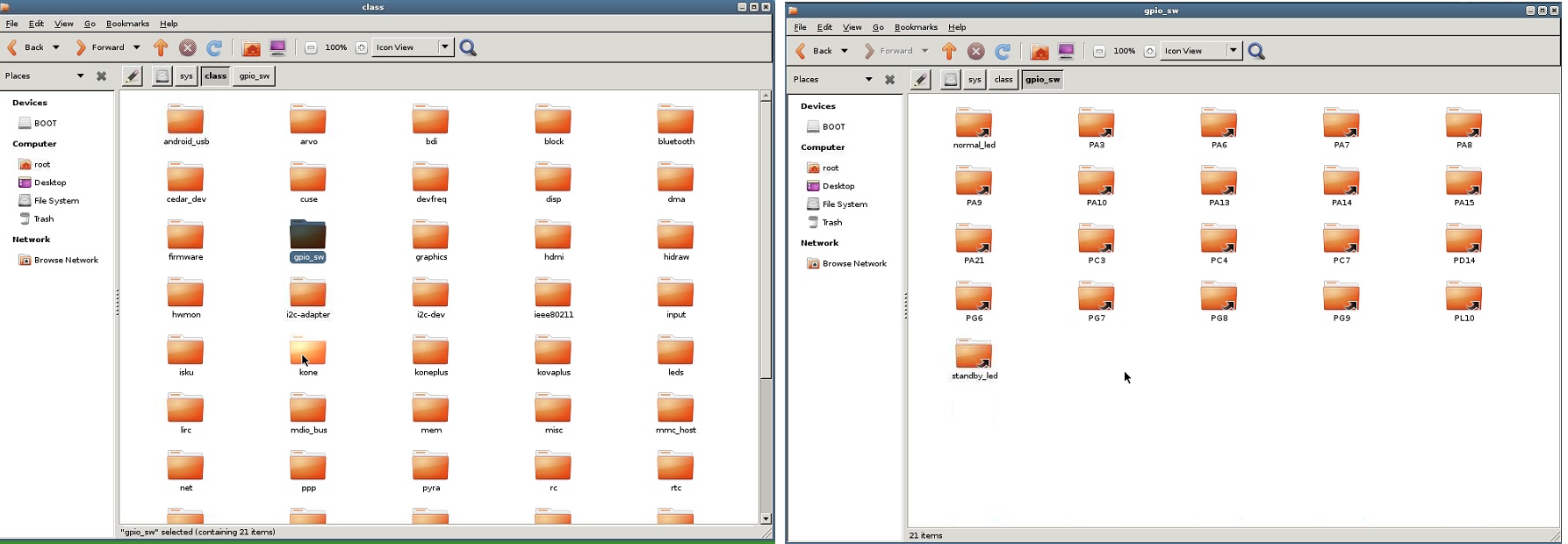
i have not any folder "gpio" in class folder .
what am i do ? :(
can you create a new topic with all steps after full fix on orange pi ?
thank you. i follow this topic -
@marceloaqno You were right, I wasn't using the correct branch. Your instructions though did not work for me
root@opi-pc-1:~# git clone https://github.com/marceloaqno/MySensors/tree/spidev marceloaqno-spidev
Cloning into 'marceloaqno-spidev'...
fatal: repository 'https://github.com/marceloaqno/MySensors/tree/spidev/' not found
Anyway, I found another way:
git clone https://github.com/marceloaqno/MySensors.git marceloaqno-spidev
cd marceloaqno-spidev/
git pull origin spidev
./configure
make
This time it compiled successfuly, but when I fired up mysgw all I got was:
mysgw: Starting gateway...
mysgw: Protocol version - 2.2.0-beta
with no other output.
Just to be sure we're on the same note, what is the wiring schematic I should use? When I first started to tinker with RF24 on OPi I found at least two wiring schematics.
For reference here's the gpio readall on my OPi PC:+-----+-----+----------+------+---+-Orange Pi+---+---+------+---------+-----+--+ | BCM | wPi | Name | Mode | V | Physical | V | Mode | Name | wPi | BCM | +-----+-----+----------+------+---+----++----+---+------+----------+-----+-----+ | | | 3.3v | | | 1 || 2 | | | 5v | | | | 12 | 8 | SDA.0 | ALT5 | 0 | 3 || 4 | | | 5V | | | | 11 | 9 | SCL.0 | ALT5 | 0 | 5 || 6 | | | 0v | | | | 6 | 7 | GPIO.7 | ALT3 | 0 | 7 || 8 | 0 | ALT4 | TxD3 | 15 | 13 | | | | 0v | | | 9 || 10 | 0 | ALT4 | RxD3 | 16 | 14 | | 1 | 0 | RxD2 | ALT5 | 0 | 11 || 12 | 0 | ALT3 | GPIO.1 | 1 | 110 | | 0 | 2 | TxD2 | ALT5 | 1 | 13 || 14 | | | 0v | | | | 3 | 3 | CTS2 | ALT5 | 0 | 15 || 16 | 0 | ALT3 | GPIO.4 | 4 | 68 | | | | 3.3v | | | 17 || 18 | 0 | ALT3 | GPIO.5 | 5 | 71 | | 64 | 12 | MOSI | ALT4 | 0 | 19 || 20 | | | 0v | | | | 65 | 13 | MISO | ALT4 | 0 | 21 || 22 | 0 | ALT5 | RTS2 | 6 | 2 | | 66 | 14 | SCLK | ALT4 | 0 | 23 || 24 | 0 | ALT4 | CE0 | 10 | 67 | | | | 0v | | | 25 || 26 | 0 | ALT3 | GPIO.11 | 11 | 21 | | 19 | 30 | SDA.1 | ALT4 | 0 | 27 || 28 | 0 | ALT4 | SCL.1 | 31 | 18 | | 7 | 21 | GPIO.21 | ALT3 | 0 | 29 || 30 | | | 0v | | | | 8 | 22 | GPIO.22 | ALT3 | 0 | 31 || 32 | 0 | ALT5 | RTS1 | 26 | 200 | | 9 | 23 | GPIO.23 | OUT | 0 | 33 || 34 | | | 0v | | | | 10 | 24 | GPIO.24 | OUT | 1 | 35 || 36 | 0 | ALT5 | CTS1 | 27 | 201 | | 20 | 25 | GPIO.25 | ALT3 | 0 | 37 || 38 | 0 | ALT5 | TxD1 | 28 | 198 | | | | 0v | | | 39 || 40 | 0 | ALT5 | RxD1 | 29 | 199 | +-----+-----+----------+------+---+----++----+---+------+----------+-----+-----+ | BCM | wPi | Name | Mode | V | Physical | V | Mode | Name | wPi | BCM | +-----+-----+----------+------+---+-Orange Pi+---+------+----------+-----+-----+ -
@marceloaqno You were right, I wasn't using the correct branch. Your instructions though did not work for me
root@opi-pc-1:~# git clone https://github.com/marceloaqno/MySensors/tree/spidev marceloaqno-spidev
Cloning into 'marceloaqno-spidev'...
fatal: repository 'https://github.com/marceloaqno/MySensors/tree/spidev/' not found
Anyway, I found another way:
git clone https://github.com/marceloaqno/MySensors.git marceloaqno-spidev
cd marceloaqno-spidev/
git pull origin spidev
./configure
make
This time it compiled successfuly, but when I fired up mysgw all I got was:
mysgw: Starting gateway...
mysgw: Protocol version - 2.2.0-beta
with no other output.
Just to be sure we're on the same note, what is the wiring schematic I should use? When I first started to tinker with RF24 on OPi I found at least two wiring schematics.
For reference here's the gpio readall on my OPi PC:+-----+-----+----------+------+---+-Orange Pi+---+---+------+---------+-----+--+ | BCM | wPi | Name | Mode | V | Physical | V | Mode | Name | wPi | BCM | +-----+-----+----------+------+---+----++----+---+------+----------+-----+-----+ | | | 3.3v | | | 1 || 2 | | | 5v | | | | 12 | 8 | SDA.0 | ALT5 | 0 | 3 || 4 | | | 5V | | | | 11 | 9 | SCL.0 | ALT5 | 0 | 5 || 6 | | | 0v | | | | 6 | 7 | GPIO.7 | ALT3 | 0 | 7 || 8 | 0 | ALT4 | TxD3 | 15 | 13 | | | | 0v | | | 9 || 10 | 0 | ALT4 | RxD3 | 16 | 14 | | 1 | 0 | RxD2 | ALT5 | 0 | 11 || 12 | 0 | ALT3 | GPIO.1 | 1 | 110 | | 0 | 2 | TxD2 | ALT5 | 1 | 13 || 14 | | | 0v | | | | 3 | 3 | CTS2 | ALT5 | 0 | 15 || 16 | 0 | ALT3 | GPIO.4 | 4 | 68 | | | | 3.3v | | | 17 || 18 | 0 | ALT3 | GPIO.5 | 5 | 71 | | 64 | 12 | MOSI | ALT4 | 0 | 19 || 20 | | | 0v | | | | 65 | 13 | MISO | ALT4 | 0 | 21 || 22 | 0 | ALT5 | RTS2 | 6 | 2 | | 66 | 14 | SCLK | ALT4 | 0 | 23 || 24 | 0 | ALT4 | CE0 | 10 | 67 | | | | 0v | | | 25 || 26 | 0 | ALT3 | GPIO.11 | 11 | 21 | | 19 | 30 | SDA.1 | ALT4 | 0 | 27 || 28 | 0 | ALT4 | SCL.1 | 31 | 18 | | 7 | 21 | GPIO.21 | ALT3 | 0 | 29 || 30 | | | 0v | | | | 8 | 22 | GPIO.22 | ALT3 | 0 | 31 || 32 | 0 | ALT5 | RTS1 | 26 | 200 | | 9 | 23 | GPIO.23 | OUT | 0 | 33 || 34 | | | 0v | | | | 10 | 24 | GPIO.24 | OUT | 1 | 35 || 36 | 0 | ALT5 | CTS1 | 27 | 201 | | 20 | 25 | GPIO.25 | ALT3 | 0 | 37 || 38 | 0 | ALT5 | TxD1 | 28 | 198 | | | | 0v | | | 39 || 40 | 0 | ALT5 | RxD1 | 29 | 199 | +-----+-----+----------+------+---+----++----+---+------+----------+-----+-----+ | BCM | wPi | Name | Mode | V | Physical | V | Mode | Name | wPi | BCM | +-----+-----+----------+------+---+-Orange Pi+---+------+----------+-----+-----+Just a question the command "gpio readall" does that does show the actual status of the system, or is it just a fixed table that is printed on screen....
Look at mine:
root@orangepizero:~# gpio readall
 +-----+-----+----------+------+---+-Orange Pi+---+---+------+---------+-----+--+
 | BCM | wPi |   Name   | Mode | V | Physical | V | Mode | Name     | wPi | BCM |
 +-----+-----+----------+------+---+----++----+---+------+----------+-----+-----+
 |     |     |     3.3v |      |   |  1 || 2  |   |      | 5v       |     |     |
 |  12 |   8 |    SDA.0 | ALT5 | 0 |  3 || 4  |   |      | 5V       |     |     |
 |  11 |   9 |    SCL.0 | ALT5 | 0 |  5 || 6  |   |      | 0v       |     |     |
 |   6 |   7 |   GPIO.7 | ALT3 | 0 |  7 || 8  | 1 | OUT  | TxD3     | 15  | 13  |
 |     |     |       0v |      |   |  9 || 10 | 0 | ALT5 | RxD3     | 16  | 14  |
 |   1 |   0 |     RxD2 | ALT5 | 0 | 11 || 12 | 0 | ALT3 | GPIO.1   | 1   | 110 |
 |   0 |   2 |     TxD2 | ALT5 | 0 | 13 || 14 |   |      | 0v       |     |     |
 |   3 |   3 |     CTS2 | ALT3 | 0 | 15 || 16 | 0 | ALT3 | GPIO.4   | 4   | 68  |
 |     |     |     3.3v |      |   | 17 || 18 | 0 | ALT3 | GPIO.5   | 5   | 71  |
 |  64 |  12 |     MOSI | ALT4 | 0 | 19 || 20 |   |      | 0v       |     |     |
 |  65 |  13 |     MISO | ALT4 | 0 | 21 || 22 | 0 | OUT  | RTS2     | 6   | 2   |
 |  66 |  14 |     SCLK | ALT4 | 0 | 23 || 24 | 0 | ALT4 | CE0      | 10  | 67  |
 |     |     |       0v |      |   | 25 || 26 | 0 | ALT3 | GPIO.11  | 11  | 21  |
 |  19 |  30 |    SDA.1 | ALT4 | 0 | 27 || 28 | 0 | ALT4 | SCL.1    | 31  | 18  |
 |   7 |  21 |  GPIO.21 | ALT3 | 0 | 29 || 30 |   |      | 0v       |     |     |
 |   8 |  22 |  GPIO.22 | ALT3 | 0 | 31 || 32 | 0 | ALT3 | RTS1     | 26  | 200 |
 |   9 |  23 |  GPIO.23 |  OUT | 0 | 33 || 34 |   |      | 0v       |     |     |
 |  10 |  24 |  GPIO.24 |  OUT | 1 | 35 || 36 | 0 | ALT3 | CTS1     | 27  | 201 |
 |  20 |  25 |  GPIO.25 |  OUT | 1 | 37 || 38 | 0 | ALT5 | TxD1     | 28  | 198 |
 |     |     |       0v |      |   | 39 || 40 | 0 | ALT5 | RxD1     | 29  | 199 |
 +-----+-----+----------+------+---+----++----+---+------+----------+-----+-----+
 | BCM | wPi |   Name   | Mode | V | Physical | V | Mode | Name     | wPi | BCM |
 +-----+-----+----------+------+---+-Orange Pi+---+------+----------+-----+-----+
It is the same... and shows 40 pins while the OPI Zero only has 26.......
There are some small differences between our tables in the naming column... so i guess it really reads the status / names of the pins.. Anyhow still strange that 40 pins are shown instead of 26 for the zero.. -
@marceloaqno: are you planning to create a pull request? also, like @Reza suggested i think it would be smart to gather all information somehwhere, unfortunately mysensors does not seem to have a wiki. can we write an article somehow? i could take care of that.
-
@marceloaqno: are you planning to create a pull request? also, like @Reza suggested i think it would be smart to gather all information somehwhere, unfortunately mysensors does not seem to have a wiki. can we write an article somehow? i could take care of that.
@mihai.aldea sorry about the github link mistake.
@pansen Yes, I will.
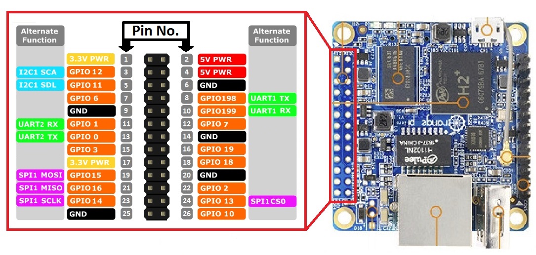
Is the orientation of the pins correct in the image?
-
@mihai.aldea sorry about the github link mistake.
@pansen Yes, I will.
Is the orientation of the pins correct in the image?
Nope pinout is reversed!,
The link below shows the correct one!
https://oshlab.com/orange-pi-zero-pinout/ -
Nope pinout is reversed!,
The link below shows the correct one!
https://oshlab.com/orange-pi-zero-pinout/@Tag Oops, did I get it right this time (I reuploaded the image)?
-
Build the RF24 lib, without erros on the OPI Zero. and am now able to start the tools and radio seems to be recognised!. (was a faulty breadboard wire.... :( )
Used the follwing to for the radio:
RF24 radio(2,0);Output from gettingstarted:
root@orangepizero:~/rf24libs/RF24/examples_linux# ./gettingstarted RF24/examples/GettingStarted/ STATUS = 0x00 RX_DR=0 TX_DS=0 MAX_RT=0 RX_P_NO=0 TX_FULL=0 RX_ADDR_P0-1 = 0x0000000000 0xff00000000 RX_ADDR_P2-5 = 0xff 0xff 0xff 0xff TX_ADDR = 0xffffffffff RX_PW_P0-6 = 0xff 0xff 0xff 0xff 0xff 0xff EN_AA = 0xff EN_RXADDR = 0xff RF_CH = 0xbc RF_SETUP = 0xff CONFIG = 0xff DYNPD/FEATURE = 0xff 0xff Data Rate = 1MBPS Model = nRF24L01 CRC Length = 16 bits PA Power = PA_MAX ************ Role Setup *********** Choose a role: Enter 0 for pong_back, 1 for ping_out (CTRL+C to exit) > -
Build the RF24 lib, without erros on the OPI Zero. and am now able to start the tools and radio seems to be recognised!. (was a faulty breadboard wire.... :( )
Used the follwing to for the radio:
RF24 radio(2,0);Output from gettingstarted:
root@orangepizero:~/rf24libs/RF24/examples_linux# ./gettingstarted RF24/examples/GettingStarted/ STATUS = 0x00 RX_DR=0 TX_DS=0 MAX_RT=0 RX_P_NO=0 TX_FULL=0 RX_ADDR_P0-1 = 0x0000000000 0xff00000000 RX_ADDR_P2-5 = 0xff 0xff 0xff 0xff TX_ADDR = 0xffffffffff RX_PW_P0-6 = 0xff 0xff 0xff 0xff 0xff 0xff EN_AA = 0xff EN_RXADDR = 0xff RF_CH = 0xbc RF_SETUP = 0xff CONFIG = 0xff DYNPD/FEATURE = 0xff 0xff Data Rate = 1MBPS Model = nRF24L01 CRC Length = 16 bits PA Power = PA_MAX ************ Role Setup *********** Choose a role: Enter 0 for pong_back, 1 for ping_out (CTRL+C to exit) >@Tag Could you fill this table with your current setup?
nRF24L01 | OrangePi | OrangePi | phyPin | GPIO _________|_______________________ VCC | 3V3-PWR | 3V3-PWR GND | GND | GND CSN | | CE | | MOSI | 19 | 15 SCK | 23 | 14 MISO | 21 | 16 -
@Tag Could you fill this table with your current setup?
nRF24L01 | OrangePi | OrangePi | phyPin | GPIO _________|_______________________ VCC | 3V3-PWR | 3V3-PWR GND | GND | GND CSN | | CE | | MOSI | 19 | 15 SCK | 23 | 14 MISO | 21 | 16Sure here it is,
nRF24L01 | OrangePi  | OrangePi
         | phyPin    | GPIO
_________|_______________________
VCC      | 3V3-PWR   | 3V3-PWR
GND      | GND       | GND
CSN      | 24        | 13
CE       | 22        | 2
MOSI     | 19        | 15
SCK      | 23        | 14
MISO     | 21        | 16
Radio seems to be recognised, still need to test data transfer...
-
Sure here it is,
nRF24L01 | OrangePi  | OrangePi
         | phyPin    | GPIO
_________|_______________________
VCC      | 3V3-PWR   | 3V3-PWR
GND      | GND       | GND
CSN      | 24        | 13
CE       | 22        | 2
MOSI     | 19        | 15
SCK      | 23        | 14
MISO     | 21        | 16
Radio seems to be recognised, still need to test data transfer...
I created the draft for the official article: https://www.mysensors.org/build/orange
-
I created the draft for the official article: https://www.mysensors.org/build/orange
-
@marceloaqno and everyone else involved in this effort: great work! I love when people come together to solve a problem.
@marceloaqno
@mfalkvidd @Tag @pansen @Reza @mihai.aldea @hausingerWooow woow woow !!!
Only few days "off" and the problem to make work Mysensors on OPI are solved.
So many many thanks to all people here that have been involved to make that OPI good little boards can work with Mysensors.
This is the proof that when good people join can reach the most difficult achievements and all humanity can benefit.
Awesome work !
Regards
-
I created the draft for the official article: https://www.mysensors.org/build/orange
Great work!!! the GPIO part most probably needs some additions for OPI zero on the topic of the spidev1.0 driver and the GPIO pins, send it to you once i got everything documented.
Really many thanks for your hard work here!!
-
I created the draft for the official article: https://www.mysensors.org/build/orange
@marceloaqno
thank you. but i have error:root@OrangePI:~# ls /sys/class/gpio/export ls: cannot access /sys/class/gpio/export: No such file or directory root@OrangePI:~# modprobe gpio-sunxi root@OrangePI:~# ls /sys/class/gpio/export ls: cannot access /sys/class/gpio/export: No such file or directoryin class folder i dont have gpio folder (i use a orangepi one with ubuntu os )
i
-
root@OrangePI:~# git clone https://github.com/marceloaqno/MySensors.git orangepi Cloning into 'orangepi'... remote: Counting objects: 13858, done. remote: Compressing objects: 100% (50/50), done. remote: Total 13858 (delta 17), reused 0 (delta 0), pack-reused 13808 Receiving objects: 100% (13858/13858), 9.68 MiB | 79.00 KiB/s, done. Resolving deltas: 100% (8304/8304), done. Checking connectivity... done. root@OrangePI:~# cd orangepi/ root@OrangePI:~/orangepi# git pull origin spidev From https://github.com/marceloaqno/MySensors * branch spidev -> FETCH_HEAD Updating 570b607..63e1a81 Fast-forward Makefile | 16 +++ MyConfig.h | 4 + MySensors.h | 2 +- configure | 79 ++++++++++--- core/MyHwLinuxGeneric.cpp | 17 +++ core/MyHwLinuxGeneric.h | 12 +- core/MyHwRPi.cpp | 1 + core/MyHwRPi.h | 28 ----- core/MyMainLinux.cpp | 30 ++--- drivers/{RPi => BCM}/SPI.cpp | 10 +- drivers/{RPi => BCM}/SPI.h | 116 ++++++++++++------- drivers/{RPi => BCM}/Wire.cpp | 0 drivers/{RPi => BCM}/Wire.h | 1 + drivers/Linux/Arduino.h | 22 +++- drivers/Linux/GPIO.cpp | 119 ++++++++++++++++++++ drivers/Linux/GPIO.h | 47 ++++++++ drivers/Linux/Stream.h | 1 + drivers/Linux/compatibility.cpp | 11 +- drivers/{RPi/rpi_util.cpp => Linux/interrupt.cpp} | 144 +++++------------------- drivers/Linux/interrupt.h | 45 ++++++++ drivers/RF24/RF24.cpp | 4 +- drivers/RF24/RF24.h | 2 +- drivers/RPi/RPi.cpp | 59 ++++++++++ drivers/RPi/RPi.h | 22 ++++ drivers/RPi/piHiPri.c | 49 -------- drivers/RPi/rpi_util.h | 76 ------------- drivers/RPi/wiring.cpp | 72 ++++++++++++ drivers/RPi/wiring.h | 24 ++++ drivers/SPIDEV/SPI.cpp | 223 +++++++++++++++++++++++++++++++++++++ drivers/SPIDEV/SPI.h | 178 +++++++++++++++++++++++++++++ 30 files changed, 1054 insertions(+), 360 deletions(-) rename drivers/{RPi => BCM}/SPI.cpp (100%) rename drivers/{RPi => BCM}/SPI.h (62%) rename drivers/{RPi => BCM}/Wire.cpp (100%) rename drivers/{RPi => BCM}/Wire.h (99%) create mode 100644 drivers/Linux/GPIO.cpp create mode 100644 drivers/Linux/GPIO.h rename drivers/{RPi/rpi_util.cpp => Linux/interrupt.cpp} (63%) create mode 100644 drivers/Linux/interrupt.h create mode 100644 drivers/RPi/RPi.cpp create mode 100644 drivers/RPi/RPi.h delete mode 100644 drivers/RPi/piHiPri.c delete mode 100644 drivers/RPi/rpi_util.h create mode 100644 drivers/RPi/wiring.cpp create mode 100644 drivers/RPi/wiring.h create mode 100644 drivers/SPIDEV/SPI.cpp create mode 100644 drivers/SPIDEV/SPI.h root@OrangePI:~/orangepi# ./configure [SECTION] Detecting target machine. [OK] machine detected: SoC=H3, Type=unknown, CPU=armv7l. [SECTION] Detecting SPI driver. [OK] SPI driver detected:SPIDEV. [SECTION] Detecting init system. [OK] init system detected: systemd. [SECTION] Saving configuration. [SECTION] Cleaning previous builds. [OK] Finished. root@OrangePI:~/orangepi# make gcc -MT build/drivers/Linux/log.o -MMD -MP -march=armv8-a -mtune=cortex-a53 -mfpu=neon-vfpv4 -mfloat-abi=hard -DMY_RADIO_NRF24 -DMY_GATEWAY_LINUX -DMY_DEBUG -DLINUX_SPI_SPIDEV -DLINUX_ARCH_ORANGEPI -Ofast -g -Wall -Wextra -I. -I./core -I./drivers/Linux -I./drivers/SPIDEV -c drivers/Linux/log.c -o build/drivers/Linux/log.o g++ -MT build/drivers/Linux/IPAddress.o -MMD -MP -march=armv8-a -mtune=cortex-a53 -mfpu=neon-vfpv4 -mfloat-abi=hard -DMY_RADIO_NRF24 -DMY_GATEWAY_LINUX -DMY_DEBUG -DLINUX_SPI_SPIDEV -DLINUX_ARCH_ORANGEPI -Ofast -g -Wall -Wextra -I. -I./core -I./drivers/Linux -I./drivers/SPIDEV -c drivers/Linux/IPAddress.cpp -o build/drivers/Linux/IPAddress.o g++ -MT build/drivers/Linux/noniso.o -MMD -MP -march=armv8-a -mtune=cortex-a53 -mfpu=neon-vfpv4 -mfloat-abi=hard -DMY_RADIO_NRF24 -DMY_GATEWAY_LINUX -DMY_DEBUG -DLINUX_SPI_SPIDEV -DLINUX_ARCH_ORANGEPI -Ofast -g -Wall -Wextra -I. -I./core -I./drivers/Linux -I./drivers/SPIDEV -c drivers/Linux/noniso.cpp -o build/drivers/Linux/noniso.o g++ -MT build/drivers/Linux/GPIO.o -MMD -MP -march=armv8-a -mtune=cortex-a53 -mfpu=neon-vfpv4 -mfloat-abi=hard -DMY_RADIO_NRF24 -DMY_GATEWAY_LINUX -DMY_DEBUG -DLINUX_SPI_SPIDEV -DLINUX_ARCH_ORANGEPI -Ofast -g -Wall -Wextra -I. -I./core -I./drivers/Linux -I./drivers/SPIDEV -c drivers/Linux/GPIO.cpp -o build/drivers/Linux/GPIO.o g++ -MT build/drivers/Linux/Print.o -MMD -MP -march=armv8-a -mtune=cortex-a53 -mfpu=neon-vfpv4 -mfloat-abi=hard -DMY_RADIO_NRF24 -DMY_GATEWAY_LINUX -DMY_DEBUG -DLINUX_SPI_SPIDEV -DLINUX_ARCH_ORANGEPI -Ofast -g -Wall -Wextra -I. -I./core -I./drivers/Linux -I./drivers/SPIDEV -c drivers/Linux/Print.cpp -o build/drivers/Linux/Print.o g++ -MT build/drivers/Linux/EthernetClient.o -MMD -MP -march=armv8-a -mtune=cortex-a53 -mfpu=neon-vfpv4 -mfloat-abi=hard -DMY_RADIO_NRF24 -DMY_GATEWAY_LINUX -DMY_DEBUG -DLINUX_SPI_SPIDEV -DLINUX_ARCH_ORANGEPI -Ofast -g -Wall -Wextra -I. -I./core -I./drivers/Linux -I./drivers/SPIDEV -c drivers/Linux/EthernetClient.cpp -o build/drivers/Linux/EthernetClient.o g++ -MT build/drivers/Linux/SerialPort.o -MMD -MP -march=armv8-a -mtune=cortex-a53 -mfpu=neon-vfpv4 -mfloat-abi=hard -DMY_RADIO_NRF24 -DMY_GATEWAY_LINUX -DMY_DEBUG -DLINUX_SPI_SPIDEV -DLINUX_ARCH_ORANGEPI -Ofast -g -Wall -Wextra -I. -I./core -I./drivers/Linux -I./drivers/SPIDEV -c drivers/Linux/SerialPort.cpp -o build/drivers/Linux/SerialPort.o g++ -MT build/drivers/Linux/Stream.o -MMD -MP -march=armv8-a -mtune=cortex-a53 -mfpu=neon-vfpv4 -mfloat-abi=hard -DMY_RADIO_NRF24 -DMY_GATEWAY_LINUX -DMY_DEBUG -DLINUX_SPI_SPIDEV -DLINUX_ARCH_ORANGEPI -Ofast -g -Wall -Wextra -I. -I./core -I./drivers/Linux -I./drivers/SPIDEV -c drivers/Linux/Stream.cpp -o build/drivers/Linux/Stream.o g++ -MT build/drivers/Linux/compatibility.o -MMD -MP -march=armv8-a -mtune=cortex-a53 -mfpu=neon-vfpv4 -mfloat-abi=hard -DMY_RADIO_NRF24 -DMY_GATEWAY_LINUX -DMY_DEBUG -DLINUX_SPI_SPIDEV -DLINUX_ARCH_ORANGEPI -Ofast -g -Wall -Wextra -I. -I./core -I./drivers/Linux -I./drivers/SPIDEV -c drivers/Linux/compatibility.cpp -o build/drivers/Linux/compatibility.o g++ -MT build/drivers/Linux/interrupt.o -MMD -MP -march=armv8-a -mtune=cortex-a53 -mfpu=neon-vfpv4 -mfloat-abi=hard -DMY_RADIO_NRF24 -DMY_GATEWAY_LINUX -DMY_DEBUG -DLINUX_SPI_SPIDEV -DLINUX_ARCH_ORANGEPI -Ofast -g -Wall -Wextra -I. -I./core -I./drivers/Linux -I./drivers/SPIDEV -c drivers/Linux/interrupt.cpp -o build/drivers/Linux/interrupt.o drivers/Linux/interrupt.cpp: In function ‘void* interruptHandler(void*)’: drivers/Linux/interrupt.cpp:107:26: warning: ignoring return value of ‘ssize_t read(int, void*, size_t)’, declared with attribute warn_unused_result [-Wunused-result] (void)read (fd, &c, 1) ; ^ g++ -MT build/drivers/Linux/SoftEeprom.o -MMD -MP -march=armv8-a -mtune=cortex-a53 -mfpu=neon-vfpv4 -mfloat-abi=hard -DMY_RADIO_NRF24 -DMY_GATEWAY_LINUX -DMY_DEBUG -DLINUX_SPI_SPIDEV -DLINUX_ARCH_ORANGEPI -Ofast -g -Wall -Wextra -I. -I./core -I./drivers/Linux -I./drivers/SPIDEV -c drivers/Linux/SoftEeprom.cpp -o build/drivers/Linux/SoftEeprom.o g++ -MT build/drivers/Linux/EthernetServer.o -MMD -MP -march=armv8-a -mtune=cortex-a53 -mfpu=neon-vfpv4 -mfloat-abi=hard -DMY_RADIO_NRF24 -DMY_GATEWAY_LINUX -DMY_DEBUG -DLINUX_SPI_SPIDEV -DLINUX_ARCH_ORANGEPI -Ofast -g -Wall -Wextra -I. -I./core -I./drivers/Linux -I./drivers/SPIDEV -c drivers/Linux/EthernetServer.cpp -o build/drivers/Linux/EthernetServer.o g++ -MT build/examples_linux/mysgw.o -MMD -MP -march=armv8-a -mtune=cortex-a53 -mfpu=neon-vfpv4 -mfloat-abi=hard -DMY_RADIO_NRF24 -DMY_GATEWAY_LINUX -DMY_DEBUG -DLINUX_SPI_SPIDEV -DLINUX_ARCH_ORANGEPI -Ofast -g -Wall -Wextra -I. -I./core -I./drivers/Linux -I./drivers/SPIDEV -c examples_linux/mysgw.cpp -o build/examples_linux/mysgw.o In file included from ./MySensors.h:294:0, from examples_linux/mysgw.cpp:74: ./drivers/RF24/RF24.cpp:39:11: error: Not supported on this platform. hwDigitalWrite(MY_RF24_CS_PIN, level); ^ ./drivers/RF24/RF24.cpp:44:11: error: Not supported on this platform. hwDigitalWrite(MY_RF24_CE_PIN, level); ^ ./drivers/RF24/RF24.cpp:388:11: error: Not supported on this platform. hwPinMode(MY_RF24_CE_PIN,OUTPUT); ^ ./drivers/RF24/RF24.cpp:389:11: error: Not supported on this platform. hwPinMode(MY_RF24_CS_PIN,OUTPUT); ^ ./drivers/RF24/RF24.cpp:37:32: warning: unused parameter ‘level’ [-Wunused-parameter] LOCAL void RF24_csn(const bool level) ^ ./drivers/RF24/RF24.cpp:42:31: warning: unused parameter ‘level’ [-Wunused-parameter] LOCAL void RF24_ce(const bool level) ^ ./drivers/RF24/RF24.cpp: In function ‘uint8_t RF24_spiMultiByteTransfer(uint8_t, uint8_t*, uint8_t, bool)’: ./drivers/RF24/RF24.cpp:56:11: error: ‘LOW’ was not declared in this scope RF24_csn(LOW); ^ ./drivers/RF24/RF24.cpp:99:11: error: ‘HIGH’ was not declared in this scope RF24_csn(HIGH); ^ ./drivers/RF24/RF24.cpp: In function ‘void RF24_startListening()’: ./drivers/RF24/RF24.cpp:235:10: error: ‘HIGH’ was not declared in this scope RF24_ce(HIGH); ^ ./drivers/RF24/RF24.cpp: In function ‘void RF24_stopListening()’: ./drivers/RF24/RF24.cpp:241:10: error: ‘LOW’ was not declared in this scope RF24_ce(LOW); ^ ./drivers/RF24/RF24.cpp: In function ‘void RF24_powerDown()’: ./drivers/RF24/RF24.cpp:251:10: error: ‘LOW’ was not declared in this scope RF24_ce(LOW); ^ ./drivers/RF24/RF24.cpp: In function ‘bool RF24_sendMessage(uint8_t, const void*, uint8_t)’: ./drivers/RF24/RF24.cpp:269:10: error: ‘HIGH’ was not declared in this scope RF24_ce(HIGH); ^ ./drivers/RF24/RF24.cpp:276:10: error: ‘LOW’ was not declared in this scope RF24_ce(LOW); ^ ./drivers/RF24/RF24.cpp: In function ‘bool RF24_initialize()’: ./drivers/RF24/RF24.cpp:395:10: error: ‘LOW’ was not declared in this scope RF24_ce(LOW); ^ ./drivers/RF24/RF24.cpp:396:11: error: ‘HIGH’ was not declared in this scope RF24_csn(HIGH); ^ Makefile:114: recipe for target 'build/examples_linux/mysgw.o' failed make: *** [build/examples_linux/mysgw.o] Error 1 root@OrangePI:~/orangepi#``` -
You need to create the files after each boot.
After the modprobe, Issue this command:
sudo for A in 1 2 3 4 5 6 7 8 9 10 11 12 13 14 15 16; do echo "$A" > /sys/class/gpio/export ; doneThis will get you the files.
-
You need to create the files after each boot.
After the modprobe, Issue this command:
sudo for A in 1 2 3 4 5 6 7 8 9 10 11 12 13 14 15 16; do echo "$A" > /sys/class/gpio/export ; doneThis will get you the files.