Low power battery Door/Window sketch nrf24l01
-
Hi there,
I want to ask if somebody had already done a sketch for 2AA 1,5V battery powered arduino with nrf24l01 wireless radio based on interrupt pin detection ? I have done couple of hours searching and trying but I'm not very successful with it. The default sketch on this web https://www.mysensors.org/build/binary drains my batteries powered by power booster after 24 hours to 0,8 volts :cat:
In advance, I really appreciate your support in this matter
-
Hi,
I have a door sensor running on my mini sensor platform. . I used this sketch from my github.Don't use any boosters and use external resistors, not the internal pullups. With that I get a pretty good runtime.
The first part is expertimentation with older batteries, the steeper curve at the beginning was before I added the external resistors. Since then the voltage drop in about 2,5 months was around 100mV. With 3-1.8 = 1200mV that would be a runtime of about 12*2,5 = 30 months.PS The demo sketch doesn't seem to be using sleep. That means the power draw is way too high for the use of batteries.
-
I'm not having problem with my hardware with other sensors which sleeps every 2 minutes. Same hardware lasts on 1 % battery for 2 weeks , it is good result for me . I only want to know if is better sketch for battery powered door sensor which is based on interrupts wake up from sleep. It will be much better for battery.
-
Hi there,
I want to ask if somebody had already done a sketch for 2AA 1,5V battery powered arduino with nrf24l01 wireless radio based on interrupt pin detection ? I have done couple of hours searching and trying but I'm not very successful with it. The default sketch on this web https://www.mysensors.org/build/binary drains my batteries powered by power booster after 24 hours to 0,8 volts :cat:
In advance, I really appreciate your support in this matter
@warmaniac - it should not be a problem running this for atleast a year (this is how I have build my PCB - EasyPCB).
Do you use the sleep() function and did you remove the led and voltage converter on the arduino?
Here is some more info: https://www.mysensors.org/build/batteryIf you check https://www.mysensors.org/build/motion you can see a binary sketch which use sleep()
Controller: Proxmox VM - Home Assistant
MySensors GW: Arduino Uno - W5100 Ethernet, Gw Shield Nrf24l01+ 2,4Ghz
MySensors GW: Arduino Uno - Gw Shield RFM69, 433mhz
RFLink GW - Arduino Mega + RFLink Shield, 433mhz -
@warmaniac - it should not be a problem running this for atleast a year (this is how I have build my PCB - EasyPCB).
Do you use the sleep() function and did you remove the led and voltage converter on the arduino?
Here is some more info: https://www.mysensors.org/build/batteryIf you check https://www.mysensors.org/build/motion you can see a binary sketch which use sleep()
BOTH led was removed , as I said , this HW specs Im using on multiple sensors with sleep function and i dont have any problems with battery. Thanks for recommendation of using modified sketch from motion sensor. Im not expecting to remove voltage regulator because im powering my arduino with stepup booster which can be higher than 3.3 volts .
-
BOTH led was removed , as I said , this HW specs Im using on multiple sensors with sleep function and i dont have any problems with battery. Thanks for recommendation of using modified sketch from motion sensor. Im not expecting to remove voltage regulator because im powering my arduino with stepup booster which can be higher than 3.3 volts .
@warmaniac - this is not optimal since the voltage regulater has a current drain and will use your batterypower to fast. Im using a DC-DC stepup booster which provide 3.3v and then you dont need a voltage regulator.
Controller: Proxmox VM - Home Assistant
MySensors GW: Arduino Uno - W5100 Ethernet, Gw Shield Nrf24l01+ 2,4Ghz
MySensors GW: Arduino Uno - Gw Shield RFM69, 433mhz
RFLink GW - Arduino Mega + RFLink Shield, 433mhz -
@warmaniac - this is not optimal since the voltage regulater has a current drain and will use your batterypower to fast. Im using a DC-DC stepup booster which provide 3.3v and then you dont need a voltage regulator.
Yep I understand , but I ordered 10 pcs of step up boosters, all gives output voltage 3,7 -3,8V . without regulator is problem ,I think.
-
Yep I understand , but I ordered 10 pcs of step up boosters, all gives output voltage 3,7 -3,8V . without regulator is problem ,I think.
@warmaniac - So maybe you can add a diode or something in series to drop the voltage until you get new stepups, because you will be disappointing with batterylife if you use this setup.
-
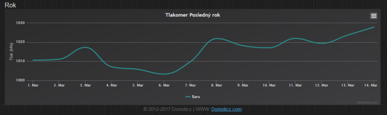
I had barometer BMP180 powered on 2xAA 1,5V , in usage from 1.March 2017 , Start battery power was 85% (not new batteries, before used) and now after 14 days of usage is 84 % , Im very satisfied. Using only without LEDs ,with power regulator on arduino.

-
I'm not having problem with my hardware with other sensors which sleeps every 2 minutes. Same hardware lasts on 1 % battery for 2 weeks , it is good result for me . I only want to know if is better sketch for battery powered door sensor which is based on interrupts wake up from sleep. It will be much better for battery.
@warmaniac said in Low power battery Door/Window sketch nrf24l01:
I'm not having problem with my hardware with other sensors which sleeps every 2 minutes. Same hardware lasts on 1 % battery for 2 weeks , it is good result for me . I only want to know if is better sketch for battery powered door sensor which is based on interrupts wake up from sleep. It will be much better for battery.
Then why don't you just use the sketch I linked to? Or simply add the parts you need (mainly sleep()) to your sketch?
-
@warmaniac said in Low power battery Door/Window sketch nrf24l01:
I'm not having problem with my hardware with other sensors which sleeps every 2 minutes. Same hardware lasts on 1 % battery for 2 weeks , it is good result for me . I only want to know if is better sketch for battery powered door sensor which is based on interrupts wake up from sleep. It will be much better for battery.
Then why don't you just use the sketch I linked to? Or simply add the parts you need (mainly sleep()) to your sketch?
I tryied , many times and changes in sketch but im failed, not waking up on interrupts , im not programmer maybe if I know better C langauge. :( Im using DIGITAL PIN 3 for magnetic sensor input.
-
I don't know if this is correct sketch but now working on interrupts , take a look please
/** * The MySensors Arduino library handles the wireless radio link and protocol * between your home built sensors/actuators and HA controller of choice. * The sensors forms a self healing radio network with optional repeaters. Each * repeater and gateway builds a routing tables in EEPROM which keeps track of the * network topology allowing messages to be routed to nodes. * * Created by Henrik Ekblad <henrik.ekblad@mysensors.org> * Copyright (C) 2013-2015 Sensnology AB * Full contributor list: https://github.com/mysensors/Arduino/graphs/contributors * * Documentation: http://www.mysensors.org * Support Forum: http://forum.mysensors.org * * This program is free software; you can redistribute it and/or * modify it under the terms of the GNU General Public License * version 2 as published by the Free Software Foundation. * ******************************* * * DESCRIPTION * * Simple binary switch example * Connect button or door/window reed switch between * digitial I/O pin 3 (BUTTON_PIN below) and GND. * http://www.mysensors.org/build/binary */ // Enable debug prints to serial monitor #define MY_DEBUG // Enable and select radio type attached #define MY_RADIO_NRF24 //#define MY_RADIO_RFM69 #include <SPI.h> #include <MySensors.h> #include <Bounce2.h> #define CHILD_ID 3 #define BUTTON_PIN 3 // Arduino Digital I/O pin for button/reed switch Bounce debouncer = Bounce(); int oldValue=-1; // Change to V_LIGHT if you use S_LIGHT in presentation below MyMessage msg(CHILD_ID,V_TRIPPED); void setup() { // Setup the button pinMode(BUTTON_PIN,INPUT); // Activate internal pull-up digitalWrite(BUTTON_PIN,HIGH); // After setting up the button, setup debouncer debouncer.attach(BUTTON_PIN); debouncer.interval(5); } void presentation() { // Register binary input sensor to gw (they will be created as child devices) // You can use S_DOOR, S_MOTION or S_LIGHT here depending on your usage. // If S_LIGHT is used, remember to update variable type you send in. See "msg" above. present(CHILD_ID, S_DOOR); } // Check if digital input has changed and send in new value void loop() { debouncer.update(); // Get the update value int value = debouncer.read(); if (value != oldValue) { // Send in the new value send(msg.set(value==HIGH ? 1 : 0)); oldValue = value; } sleep(digitalPinToInterrupt(BUTTON_PIN)-2, CHANGE, 0); }``` -
Hi,
I have some Door/window sensors, powered by a cr2032 coin battery and I was able to run them for 1 year. The sketch above it seems ok, but the secret it's not only the software, it depends on hardware too:- remove voltage regulator and led from the arduino
- choose a ceramic decoupling capacitor for your radio module, and avoid electrolytic capacitors (they have a bigger leakage current)
- I don't use any step-up converter, and use the battery to power both the radio module and arduino (reported both to work at 3V)
- a capacitor (again ceramic) of 100uF across the cell’s terminals could sustain a peak current load.
It's also better to avoid messages sending in a short time, and put some sleep in the middle, but I don't see that situation in the sketch.
-
I don't know if this is correct sketch but now working on interrupts , take a look please
/** * The MySensors Arduino library handles the wireless radio link and protocol * between your home built sensors/actuators and HA controller of choice. * The sensors forms a self healing radio network with optional repeaters. Each * repeater and gateway builds a routing tables in EEPROM which keeps track of the * network topology allowing messages to be routed to nodes. * * Created by Henrik Ekblad <henrik.ekblad@mysensors.org> * Copyright (C) 2013-2015 Sensnology AB * Full contributor list: https://github.com/mysensors/Arduino/graphs/contributors * * Documentation: http://www.mysensors.org * Support Forum: http://forum.mysensors.org * * This program is free software; you can redistribute it and/or * modify it under the terms of the GNU General Public License * version 2 as published by the Free Software Foundation. * ******************************* * * DESCRIPTION * * Simple binary switch example * Connect button or door/window reed switch between * digitial I/O pin 3 (BUTTON_PIN below) and GND. * http://www.mysensors.org/build/binary */ // Enable debug prints to serial monitor #define MY_DEBUG // Enable and select radio type attached #define MY_RADIO_NRF24 //#define MY_RADIO_RFM69 #include <SPI.h> #include <MySensors.h> #include <Bounce2.h> #define CHILD_ID 3 #define BUTTON_PIN 3 // Arduino Digital I/O pin for button/reed switch Bounce debouncer = Bounce(); int oldValue=-1; // Change to V_LIGHT if you use S_LIGHT in presentation below MyMessage msg(CHILD_ID,V_TRIPPED); void setup() { // Setup the button pinMode(BUTTON_PIN,INPUT); // Activate internal pull-up digitalWrite(BUTTON_PIN,HIGH); // After setting up the button, setup debouncer debouncer.attach(BUTTON_PIN); debouncer.interval(5); } void presentation() { // Register binary input sensor to gw (they will be created as child devices) // You can use S_DOOR, S_MOTION or S_LIGHT here depending on your usage. // If S_LIGHT is used, remember to update variable type you send in. See "msg" above. present(CHILD_ID, S_DOOR); } // Check if digital input has changed and send in new value void loop() { debouncer.update(); // Get the update value int value = debouncer.read(); if (value != oldValue) { // Send in the new value send(msg.set(value==HIGH ? 1 : 0)); oldValue = value; } sleep(digitalPinToInterrupt(BUTTON_PIN)-2, CHANGE, 0); }```@warmaniac Using debounce with a sleeping node is rather useless. Sleep() halts the millis() timer which is used by debounce. You can just sleep(100) a few ms before entering the interrupt sleep.
-
@warmaniac Using debounce with a sleeping node is rather useless. Sleep() halts the millis() timer which is used by debounce. You can just sleep(100) a few ms before entering the interrupt sleep.
if I understand correctly you mean like this ?
void loop()
{
  debouncer.update();
  // Get the update value
  int value = debouncer.read();

  if (value != oldValue) {
     // Send in the new value
     send(msg.set(value==HIGH ? 1 : 0));
     oldValue = value;
  }
sleep(200);
sleep(digitalPinToInterrupt(BUTTON_PIN)-2, CHANGE, 0);
}
Wouldn't be delay(200) doing same function ?
-
if I understand correctly you mean like this ?
void loop()
{
  debouncer.update();
  // Get the update value
  int value = debouncer.read();

  if (value != oldValue) {
     // Send in the new value
     send(msg.set(value==HIGH ? 1 : 0));
     oldValue = value;
  }
sleep(200);
sleep(digitalPinToInterrupt(BUTTON_PIN)-2, CHANGE, 0);
}
Wouldn't be delay(200) doing same function ?
@warmaniac delay() does the same thing but does not turn down the power. You can just skip the debouncer stuff.
-
Thanks for you reply !
Apologize me, if I mistaken , but ceramic capacitors in values 100 uF was only SMD? That can't I solder yet. :(@warmaniac said in Low power battery Door/Window sketch nrf24l01:
Apologize me, if I mistaken , but ceramic capacitors in values 100 uF was only SMD? That can't I solder yet. :(
Honestly it's really not a problem to solder those, not long ago (just over a couple of months :) ) I was afraid of SMD soldering and now after only a bit of training it's very easy if you stick to "big" sized SMD components or radios with castellated pins.
But even smaller size gets easy when you learn the right method, I soldered my first SMD atmega328 a few weeks ago and it is running fine :) -
I want also to specify that my sensor was running under library 1.5.4. At the moment I'm experiencing an issue under the library 2.1.1 that makes the sensor continuously wake up, so the battery discharges itself after few hours. Better under library 2.0.0 but the initialization process has many transmissions failure that give to the battery a heavy blow.
Hello! It looks like you're interested in this conversation, but you don't have an account yet.
Getting fed up of having to scroll through the same posts each visit? When you register for an account, you'll always come back to exactly where you were before, and choose to be notified of new replies (either via email, or push notification). You'll also be able to save bookmarks and upvote posts to show your appreciation to other community members.
With your input, this post could be even better 💗
Register Login