💬 Easy/Newbie PCB (RFM69 HW/W edition) for MySensors
-
@sundberg84 - Thank you for the tips, I'll write a battery sketch as you suggested and check the voltages. I'll reply with the results.
- And let me ask one more question; with switched off or lower BOD is it possible to reach longer battery life?
@ZsoltZombori - just to be clear, its either BOD or booster. They have the same result. BOD lowers the minimum voltage threshold before the chip dies, and the booster regulates the voltage up so the chip doesnt die. Same result, different methods.
-
@ZsoltZombori - just to be clear, its either BOD or booster. They have the same result. BOD lowers the minimum voltage threshold before the chip dies, and the booster regulates the voltage up so the chip doesnt die. Same result, different methods.
@sundberg84 - Ah, I see. Thank you for this information. I'll check the consumption of the node itself then with BME280 attached to find out which component is the highest power consumer.
-
@ZsoltZombori - just to be clear, its either BOD or booster. They have the same result. BOD lowers the minimum voltage threshold before the chip dies, and the booster regulates the voltage up so the chip doesnt die. Same result, different methods.
@sundberg84 - I attached the BME280 to D5 to switch on/off (to achieve less power consumption) but if I upload the program the module powers up, and connecting, send a measurement with temp, hum, bat and goes to sleep than wake up, and does nothing. If I attach the sensor to normally VCC + GND, it works fine. How can it be? What could be the problem?
-
@sundberg84 - I attached the BME280 to D5 to switch on/off (to achieve less power consumption) but if I upload the program the module powers up, and connecting, send a measurement with temp, hum, bat and goes to sleep than wake up, and does nothing. If I attach the sensor to normally VCC + GND, it works fine. How can it be? What could be the problem?
@ZsoltZombori - Did you put the pin HIGH before read? (Comfirm with a multimeter?) If you did, you might want to add a wait(); before the readings so the sensors gets time to stabilise?
Or the BME module needs some sort of initialization/startup after powered on?
-
I think you need to reinitialize the sensors before you actually read it after you power it down. I suggest you remove the instructions in setup and put everything in a function that you call every time you read the sensor, where in the beginning you set pin D5 high and at the end you set it low.
-
@ZsoltZombori - Did you put the pin HIGH before read? (Comfirm with a multimeter?) If you did, you might want to add a wait(); before the readings so the sensors gets time to stabilise?
Or the BME module needs some sort of initialization/startup after powered on?
@sundberg84 - Very good tip, I read the datasheet of bme280 sensor and it need time to initialize. I added 10 ms wait to program,
@gohan - I made a very beginner mistake as you said. The wire.begin was added to setup, I wrote it to loop, but it is not working.. -
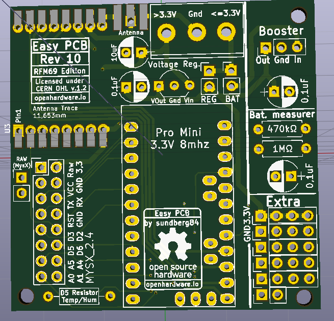
Some initial changes for Rev 10.
- MysX location changed to accept more MysX boards and align like Nrf24 version.
- Antenna location changed, radio rotated 180 degrees
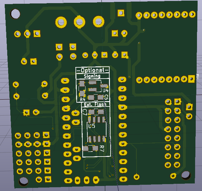
- Optional signing added
- Optional SPI flash added.
- Extra pins aligned to 2.45 vertical & horizontal
- Relocated Extra + Bat Measurer some to allow more space to booster
- Pinholes added for RFM Radio
- Changed pull-up resistor from D3 to D5 to have one more pin for Interrupt
-
@gohan - yes, but then you are not free to use the extra area as you like.
-
@gohan isn't a trace cut harder to achieve than solder a wire to the right pin?
-
Proposal.
Make two of the pads at the extra area with A4 and A5 (I2C) as more and more sensors are I2C.
Preferably the two pads next to VCC and GND.
Like the BMP280 and BME280, they are I2C with VCC, GND, SCL and SDA, so first line of pins in the extra area should be:
VCC o-o-o-o
GND o-o-o-o
A5 -o o o o
A4 -o o o oThe new layout with the SMD on the bottom layer looks good.
-
Please make the pad for the antenna on the "bottom" larger, same as "above". Most ready-made antennas are with a 90 degree wire for easier soldering.

@mickecarlsson - im not sure what you mean with:
make the pad for the antenna on the "bottom" larger, same as "above"
Picture?
I was thinking about I2c but the problem is that different sensors use different pin-orders.
Also see the discussion with gohan above about extra area. -
-
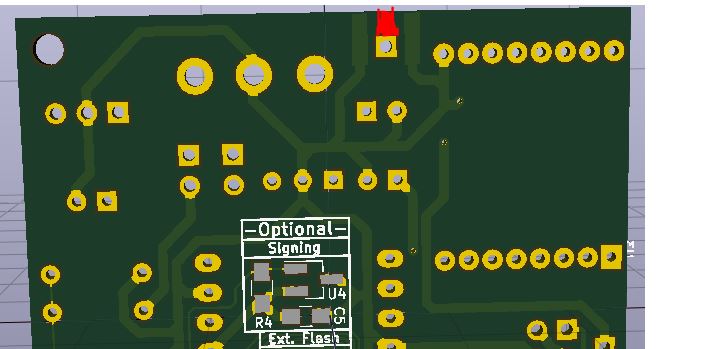
This area that I have painted red.@mickecarlsson - aha!! Okey, no problems :) I will just double-check this will not cause any issues with a SMA antenna.
-
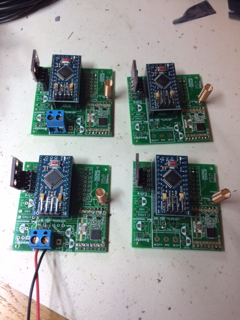
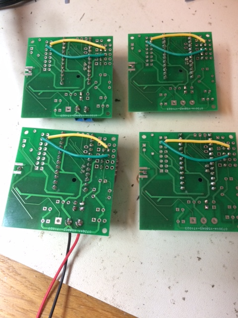
I have just finished soldering my last four easypcb with BME280:
-
I have just finished soldering my last four easypcb with BME280:
@mickecarlsson - Woao - looks great!
If you do that many with Ic2 i can understand you want extra area to be extended ;) I will think about it or maybe I can do a MysX daugherboard to you instead.Can I use your pic as a good example on the openhardware page?
-
Yes, you can use the pictures. If you need better pictues I can provide it to you.