nRF5 action!
-
-
Like NeverDie I am also having some trouble getting started with the NRF5 programming.
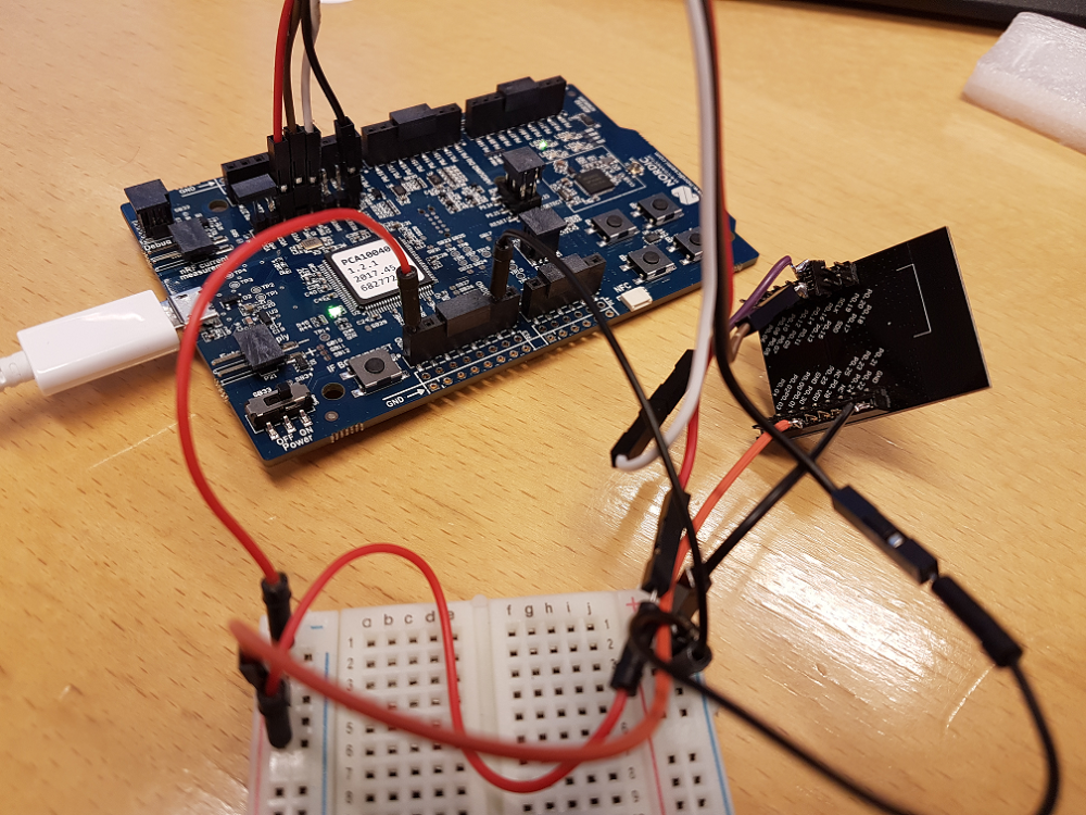
Here is my setup:
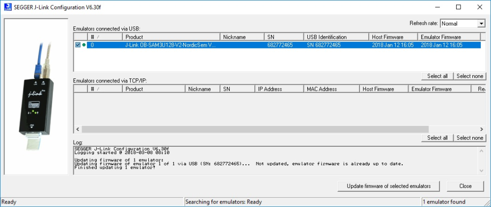
The problem "No valid JTAG Interface Configured":
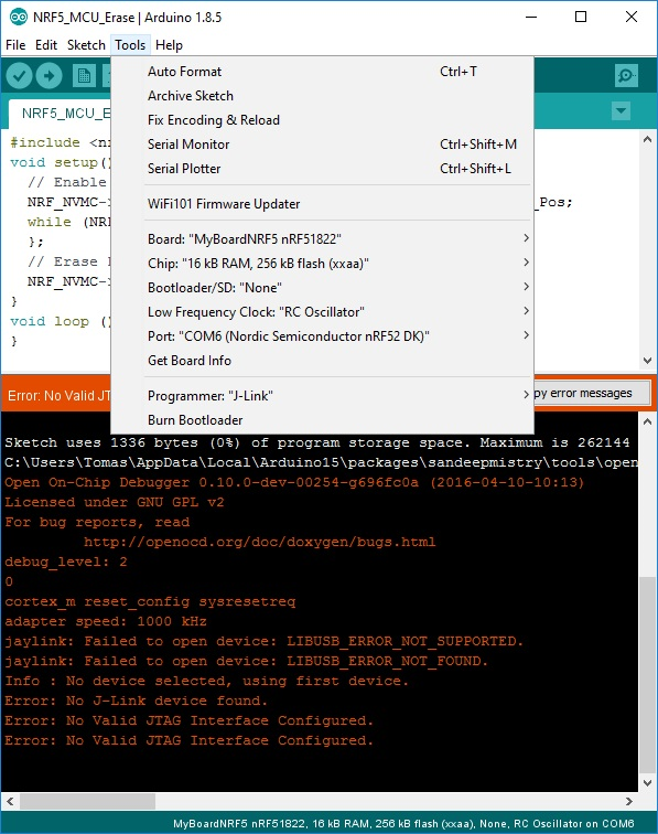
Did I miss some step to configure the J-Link somewhere?
-
@korttoma I have the same problem with the official jlink drivers. So I drag/drop the hex file from output directory to the Jlink drive at the moment.
-
@neverdie said in nRF5 Bluetooth action!:
I've always used the IDC connector.
i.e. the 10-pin connector.
-
@neverdie thank you for pointing to the power problem. I had one jumper left for my adapter to connect GND to GND and "as usual" it had a contact problem, I just replaced it and I can see the module in nRFgo Studio, even without external power.
-
Question;
I've been using the Ebyte modules and I'm making progress. But somehow the energy consumption is far too much. 11,7 mA when I use a clean sketch with hwSleep().
When I change to "Normal" Sleep() I get 0.1mA.
which one should be the right one to use, keeping in mind, I would like to wake up from an interrupt.
-
@Mika what is your experience regarding battery consumption on these?
I put together a sketch witch seems to work fine but one CR2032 just lasts a couple of days.
Sketch:
/**
 * The MySensors Arduino library handles the wireless radio link and protocol
 * between your home built sensors/actuators and HA controller of choice.
 * The sensors forms a self healing radio network with optional repeaters. Each
 * repeater and gateway builds a routing tables in EEPROM which keeps track of the
 * network topology allowing messages to be routed to nodes.
 *
 * Created by Henrik Ekblad <henrik.ekblad@mysensors.org>
 * Copyright (C) 2013-2015 Sensnology AB
 * Full contributor list: https://github.com/mysensors/Arduino/graphs/contributors
 *
 * Documentation: http://www.mysensors.org
 * Support Forum: http://forum.mysensors.org
 *
 * This program is free software; you can redistribute it and/or
 * modify it under the terms of the GNU General Public License
 * version 2 as published by the Free Software Foundation.
 *
 *******************************
 */

// Enable debug prints to serial monitor
//#define MY_DEBUG

// Define a static node address, remove if you want auto address assignment
//#define MY_NODE_ID 26                                                          // Kök
#define MY_NODE_ID 27                                                          // Test device


// Enable and select radio type attached

#define MY_RADIO_NRF5_ESB

#include <MySensors.h>

#define SN "NRF5 Scene"
#define SV "1.0"

#define CHILD_ID_SCENE 1

// PIN for the buttons
byte buttonOne = 28;

//Bounce debouncer[NUMBUTTONS];
int buttonOneoldValue;


// Pin definitions
#define DIGITAL_INPUT_INT 28   // The digital input you attached your interrupt  (Only 2 and 3 generates interrupt!)


// Sensor messages
MyMessage msgOn(CHILD_ID_SCENE, V_SCENE_ON);

// Global settings
uint16_t SceneOne = 0;
uint16_t SceneTwo = 1;


void blinkityBlink(uint8_t repetitions) {
  for (int x=0;x<repetitions;x++) {
    digitalWrite(LED_BUILTIN,HIGH);
    wait(20);
    digitalWrite(LED_BUILTIN,LOW);
    wait(100);
    digitalWrite(LED_BUILTIN,HIGH);
    wait(20);
    digitalWrite(LED_BUILTIN,LOW);
    if (x<(repetitions-1)) {  //skip waiting at the end of the final repetition
      wait(500);
    }
  }
}


/****************************************************
 *
 * Setup code
 *
 ****************************************************/

void setup() {

  hwPinMode(LED_BUILTIN,OUTPUT_D0H1);
  blinkityBlink(2);  //signify power-up and start of operations

  NRF_CLOCK->INTENSET=B11;  //enable interrupts for EVENTS_HFCLKSTARTED and  EVENTS_LFCLKSTARTED
  NRF_CLOCK->TASKS_HFCLKSTART=1;  //start the high frequency crystal oscillator clock
  while (!(NRF_CLOCK->EVENTS_HFCLKSTARTED)) {} //wait until high frequency crystal oscillator clock is up to speed and working

  hwPinMode(DIGITAL_INPUT_INT, INPUT_PULLUP);

    /// Make input & enable pull-up resistors on switch pins
  hwPinMode(buttonOne, INPUT_PULLUP);
  buttonOneoldValue = -1;


  sendBattLevel();


}

void presentation()  {
  sendSketchInfo(SN, SV);
  //present the scene controller to gateway
  wait(10);
  present(CHILD_ID_SCENE, S_SCENE_CONTROLLER);

  wait(10);
}


/***********************************************
 *
 *  Main loop function
 *
 ***********************************************/
void loop() {

  // Check for button activity

  int value = digitalRead(buttonOne);

  if (value != buttonOneoldValue)
    {
      // Send in the new value
      if (value == LOW)
      {
        send(msgOn.set(SceneOne));

        wait(20);

        send(msgOn.set(SceneTwo));

        sendBattLevel();


      }
      buttonOneoldValue = value;
    }

  sleep(digitalPinToInterrupt(DIGITAL_INPUT_INT), CHANGE, 0);

}


/********************************************
 *
 * Sends battery information (battery percentage)
 *
 * Parameters
 * - force : Forces transmission of a value
 *
 *******************************************/
void sendBattLevel()
{
    long vcc = hwCPUVoltage();

    // Calculate percentage

    vcc = vcc - 1800; // subtract 1.9V from vcc, as this is the lowest voltage we will operate at

    long percent = vcc / 14.0;
    sendBatteryLevel(percent);

}
I noticed that the chip sais:
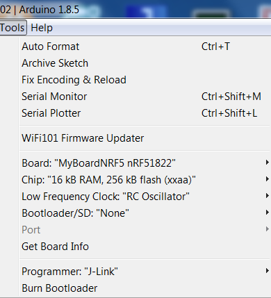
N51822
QFABC0
1646UUQFAB translates to 16kB RAM, 128kB flash and I can not even select this option in the arduino IDE. Can this be the problem?
@d00616 refer to his document for some high current consumption issue but I'm not sure what to do with the info.
Is there something wrong with my sketch or is there just an old crappy chip on the device??
-
Same result, battery out within few days, I want to do a check of current consumption, but not yet free time...
I want to try this:
https://github.com/ThingPulse/ESP8266PowerMonitor
https://thingpulse.com/2018/02/25/esp8266-monitoring-power-consumption/ -
@korttoma have you tried the code @NeverDie put together using the LPCOMP ? With a QFAAH0 (which I believe is the same version than QFABC0, but with 256K flash) he went down to something like 4µA.
From the document you link, anomaly 70, it will be necessary to add an extra wait of 36us after that line, it's strange that @NeverDie never had any problem with it. Or maybe I misunderstand the document :)void activateLpComp() { ... while (!(NRF_LPCOMP->EVENTS_READY)) {} //wait until ready ... }Test code from @NeverDie using LPCOMP is here:
https://forum.mysensors.org/topic/6961/nrf5-bluetooth-action/1307I will try it on my board (using a module with QFAAH0) tomorrow, if power consumption is as low as expected I'll try on the beacon board.
[Edit] Just checked quickly my "beacon" board and it's using a QFAAH1 chip (made in 2017), so the test might not be relevant...
-
I don't remember. I've lately been using LoRa modules, plus getting distracted by CNC, so my nRF5 work has been on hold. I'm hoping that d00616 continues to work on the software though so that more than one nRF5 interrupt can be active at a time.
-
@korttoma have you tried the code @NeverDie put together using the LPCOMP ? With a QFAAH0 (which I believe is the same version than QFABC0, but with 256K flash) he went down to something like 4µA.
From the document you link, anomaly 70, it will be necessary to add an extra wait of 36us after that line, it's strange that @NeverDie never had any problem with it. Or maybe I misunderstand the document :)void activateLpComp() { ... while (!(NRF_LPCOMP->EVENTS_READY)) {} //wait until ready ... }Test code from @NeverDie using LPCOMP is here:
https://forum.mysensors.org/topic/6961/nrf5-bluetooth-action/1307I will try it on my board (using a module with QFAAH0) tomorrow, if power consumption is as low as expected I'll try on the beacon board.
[Edit] Just checked quickly my "beacon" board and it's using a QFAAH1 chip (made in 2017), so the test might not be relevant...
@nca78 thanks for the hint.
I tried to merge my sketch with the code provided by @NeverDie but I can not seem to get it to detect my button and I don't quite understand where I should attach my button that is on pin 28 to the interrupt thingie.
Here is my code now:
//This sketch is applicable to Coincell Multisensor nRF51822, version 10

// Define a static node address, remove if you want auto address assignment
//#define MY_NODE_ID 26                                                          // Kök
#define MY_NODE_ID 27                                                          // Test device


// Enable and select radio type attached

#define MY_RADIO_NRF5_ESB

#define SN "NRF5 Scene"
#define SV "1.0"

#define CHILD_ID_SCENE 1

//#define MY_CORE_ONLY


#define IS_NRF51  //true iff the target is an nRF51.  If an nRF52, then comment this line out!

// PIN for the buttons
byte buttonOne = 28;

//Bounce debouncer[NUMBUTTONS];
int buttonOneoldValue;


// Pin definitions
//#define DIGITAL_INPUT_INT 28   // The digital input you attached your interrupt  (Only 2 and 3 generates interrupt!)


//#define I2C_INTERRUPT_PIN PIN_BUTTON1
//#define LEAK_DETECTION_PIN PIN_BUTTON1

#include <nrf.h>
#include <MySensors.h>

volatile bool button_pressed=false;

// Sensor messages
MyMessage msgOn(CHILD_ID_SCENE, V_SCENE_ON);

// Global settings
uint16_t SceneOne = 0;
uint16_t SceneTwo = 1;

void blinkityBlink(uint8_t pulses, uint8_t repetitions) {
  for (int x=0;x<repetitions;x++) {
    for (int i=0;i<pulses;i++) {
      digitalWrite(LED_BUILTIN,HIGH);
      wait(20);
      digitalWrite(LED_BUILTIN,LOW);
      wait(100);
    }
      wait(500);
  }
}

void disableNfc() {  //only applied to nRF52

#ifndef IS_NRF51
  //Make pins 9 and 10 usable as GPIO pins.
  NRF_NFCT->TASKS_DISABLE=1;  //disable NFC
  NRF_NVMC->CONFIG=1;  // Write enable the UICR
  NRF_UICR->NFCPINS=0; //Make pins 9 and 10 usable as GPIO pins.
  NRF_NVMC->CONFIG=0;  // Put the UICR back into read-only mode.
#endif
}


void turnOffRadio() {
  NRF_RADIO->TASKS_DISABLE=1;
  while (!(NRF_RADIO->EVENTS_DISABLED)) {}  //until radio is confirmed disabled
}

void turnOffUarte0() {
#ifndef IS_NRF51
  NRF_UARTE0->TASKS_STOPRX = 1;
  NRF_UARTE0->TASKS_STOPTX = 1;
  NRF_UARTE0->TASKS_SUSPEND = 1;
  NRF_UARTE0->ENABLE=0;  //disable UART0
  while (NRF_UARTE0->ENABLE!=0) {};  //wait until UART0 is confirmed disabled.
#endif

#ifdef IS_NRF51
  NRF_UART0->TASKS_STOPRX = 1;
  NRF_UART0->TASKS_STOPTX = 1;
  NRF_UART0->TASKS_SUSPEND = 1;
  NRF_UART0->ENABLE=0;  //disable UART0
  while (NRF_UART0->ENABLE!=0) {};  //wait until UART0 is confirmed disabled.
#endif
}

void turnOffAdc() {
#ifndef IS_NRF51
  if (NRF_SAADC->ENABLE) { //if enabled, then disable the SAADC
    NRF_SAADC->TASKS_STOP=1;
    while (NRF_SAADC->EVENTS_STOPPED) {} //wait until stopping of SAADC is confirmed
    NRF_SAADC->ENABLE=0;  //disable the SAADC
    while (NRF_SAADC->ENABLE) {} //wait until the disable is confirmed
  }
#endif
}


void turnOffHighFrequencyClock() {
    NRF_CLOCK->TASKS_HFCLKSTOP = 1;
    while ((NRF_CLOCK->HFCLKSTAT) & 0x0100) {}  //wait as long as HF clock is still running.
}


void mySleepPrepare()
{
  turnOffHighFrequencyClock();
  turnOffRadio();
  turnOffUarte0();
}


void activateLpComp() {
  //NRF_LPCOMP->PSEL=1; // monitor AIN1 (pin P0.03 on nRF52832 test board).
  //while (!(NRF_LPCOMP->PSEL==1)) {} //wait until confirmed
  NRF_LPCOMP->PSEL=3; // monitor AIN3 (pin P0.02 on nRF51822 for coincell_multisensor_v10)
  while (!(NRF_LPCOMP->PSEL==3)) {} //wait until confirmed
  NRF_LPCOMP->REFSEL=1;  // choose 1/4 VDD as the reference voltage
  while (!(NRF_LPCOMP->REFSEL==1)) {} //wait until confirmed
  NRF_LPCOMP->ANADETECT=1;  //detect UP events.
  while (NRF_LPCOMP->ANADETECT!=1) {} //wait until confirmed
  NRF_LPCOMP->INTENSET=B0100;  //Enable interrupt for UP event
  while (!(NRF_LPCOMP->INTENSET==B0100)) {} //wait until confirmed
  NRF_LPCOMP->ENABLE=1;  //Enable LPCOMP
  while (!(NRF_LPCOMP->ENABLE==1)) {} //wait until confirmed
  NRF_LPCOMP->TASKS_START=1;  //start the LPCOMP
  while (!(NRF_LPCOMP->EVENTS_READY)) {}  //wait until ready

  NVIC_SetPriority(LPCOMP_IRQn, 15);
  NVIC_ClearPendingIRQ(LPCOMP_IRQn);
  NVIC_EnableIRQ(LPCOMP_IRQn);
}

void suspendLpComp() { //suspend getting more interrupts from LPCOMP before the first interrupt can be handled
  if ((NRF_LPCOMP->ENABLE) && (NRF_LPCOMP->EVENTS_READY)) {  //if LPCOMP is enabled
    NRF_LPCOMP->INTENCLR=B0100;  //disable interrupt from LPCOMP
    while (NRF_LPCOMP->INTENCLR==B0100) {} //wait until confirmed
  }
}

void resumeLpComp() { //suspend getting interrupts from LPCOMP
  NRF_LPCOMP->INTENSET=B0100;  //Enable interrupt for UP event
  while (!(NRF_LPCOMP->INTENSET==B0100)) {} //wait until confirmed
}

/****************************************************
 *
 * Setup code
 *
 ****************************************************/

void setup() {

  hwInit();
  hwPinMode(LED_BUILTIN,OUTPUT_D0H1);
  disableNfc();
  turnOffAdc();
  activateLpComp();
  blinkityBlink(2,1);  //Signify end of setup with two quick pulses.
  mySleepPrepare();
  button_pressed=false;

  //NRF_CLOCK->INTENSET=B11;  //enable interrupts for EVENTS_HFCLKSTARTED and  EVENTS_LFCLKSTARTED
 // NRF_CLOCK->TASKS_HFCLKSTART=1;  //start the high frequency crystal oscillator clock
 // while (!(NRF_CLOCK->EVENTS_HFCLKSTARTED)) {} //wait until high frequency crystal oscillator clock is up to speed and working

  //hwPinMode(DIGITAL_INPUT_INT, INPUT_PULLUP);

    /// Make input & enable pull-up resistors on switch pins
  hwPinMode(buttonOne, INPUT_PULLUP);
  //buttonOneoldValue = -1;


  //sendBattLevel();


}

void presentation()  {
  sendSketchInfo(SN, SV);
  //present the scene controller to gateway
  wait(10);
  present(CHILD_ID_SCENE, S_SCENE_CONTROLLER);

  wait(10);
  sendBattLevel();

}

void sendBattLevel()
{
    long vcc = hwCPUVoltage();

    // Calculate percentage

    vcc = vcc - 1800; // subtract 1.9V from vcc, as this is the lowest voltage we will operate at

    long percent = vcc / 14.0;
    sendBatteryLevel(percent);

}

void loop() {

  sleep(10000);  //sleep for 5 seconds.
  mySleepPrepare();  //An ounce of prevention: Turn-off HF clock, etc, ASAP to save power, just in case the library's sleep() routine resumed them.
  if (button_pressed) {   //if a leak is detected
    suspendLpComp(); //suspend LPCOMP to prevent multiple interrupts
    //blinkityBlink(10,3);  //blink a lot to show that a leak was detected.
    send(msgOn.set(SceneOne));

        wait(20);

        send(msgOn.set(SceneTwo));

        sendBattLevel();
    button_pressed=false;  //Clear the semaphore
    NRF_LPCOMP->EVENTS_UP=0;  //Clear the semaphore
    resumeLpComp();  //operations of LPCOMP were suspended after detecting the LPCOMP iterrupt
  }
  else {
    blinkityBlink(1,1);  //otherwise, just one short blink to indicate the wakeup was scheduled by the RTC
  }
}


// * Reset events and read back on nRF52
//* http://infocenter.nordicsemi.com/pdf/nRF52_Series_Migration_v1.0.pdf

#if __CORTEX_M == 0x04
#define NRF5_RESET_EVENT(event)                                                 \
        event = 0;                                                                   \
        (void)event
#else
#define NRF5_RESET_EVENT(event) event = 0
#endif


// This must be in one line
extern "C" { void LPCOMP_IRQHandler(void) {button_pressed=true; NRF5_RESET_EVENT(NRF_LPCOMP->EVENTS_UP); NRF_LPCOMP->EVENTS_UP=0; MY_HW_RTC->CC[0]=(MY_HW_RTC->COUNTER+2);}}
I thought that I should do it like this:
void activateLpComp() {
   NRF_LPCOMP->PSEL=28; // monitor AIN3 (pin P0.02 on nRF51822 for coincell_multisensor_v10)
  while (!(NRF_LPCOMP->PSEL==28)) {} //wait until confirmed
But then it does not seem to run the loop anymore because I do not get the 10s blink.
-
Guys, help me understand: when do I need to enable DC-DC?
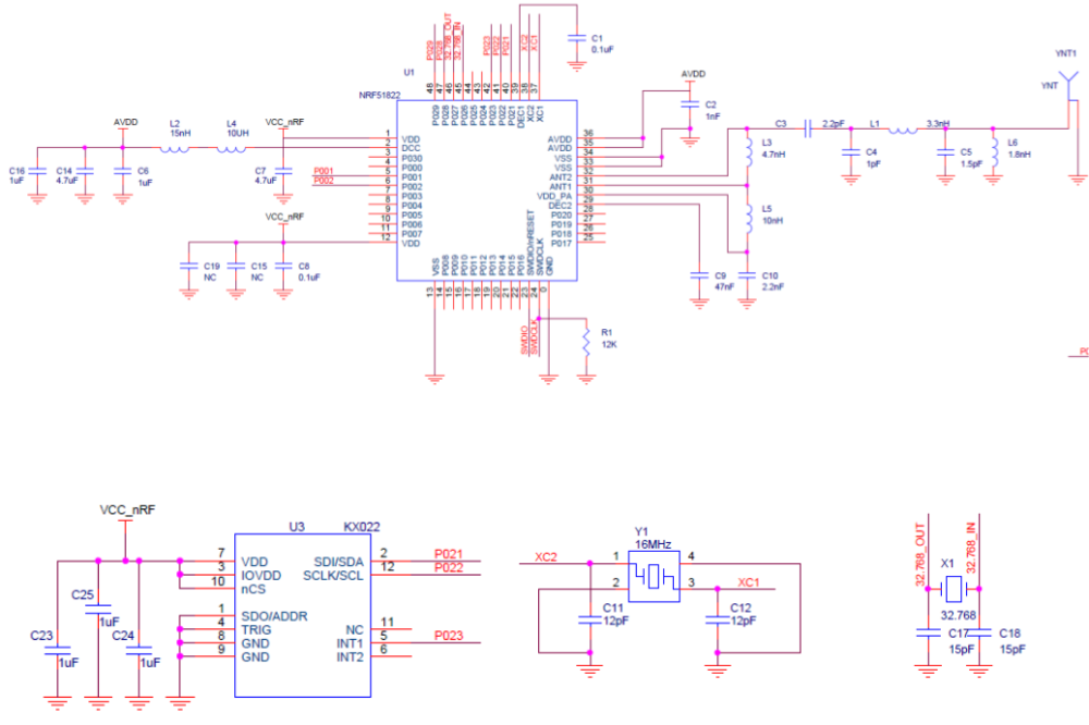
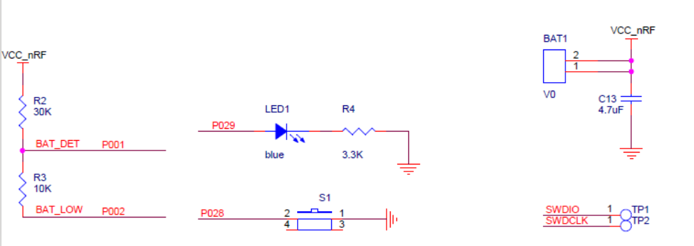
My breakout board consists of Ebyte module and a couple of buttons. Battery is CR2450 directly connected to the module.
Do I need DC-DC? -
@toyman With DC-DC, it uses roughly half the current during Tx and Rx. Seems like a no brainer to me, but you don't literally "need" to have it. I'm not aware of any downsides to it.
-
@neverdie thx. What is needed hardware-wise? Two inductors between dc and dec4? Like in your breakout board?
@toyman Correct. You can review the schematic for this project: https://www.openhardware.io/view/472/Ebyte-nRF52832-Prototyping-Board
-
I guess this is why I cant get LPCOMP to work on the device.
Eight input options (AIN0 to AIN7)I would have to use the analog inputs because pin 28 is just a general purpose I/O pin.