nRF5 action!
-
I guess this is why I cant get LPCOMP to work on the device.
Eight input options (AIN0 to AIN7)I would have to use the analog inputs because pin 28 is just a general purpose I/O pin.
-
@korttoma using MySensors NRF5 boards you should be able to assign one AINx pin to physical pin 28.
The index you need to put in the code is the AIN index not the pin number. -
@nca78 sorry but I cannot figure out how to do this. Should I do it in the MyBoardNRF5.cpp, MyBoardNRF5.h or in the sketch?
-
@korttoma sorry I said stupid things as I'm a beginner too, you can't reassign analog inputs and LPCOMP to different pins on NRF5 chips.
@nca78 it is ok, I think I will have to set up a test system with a different device with witch I can measure current consumption, attach serial logging and then try to fiddle with the code. I'm flying in the dark with this bluetooth beacon device since I cannot access any pins.
-
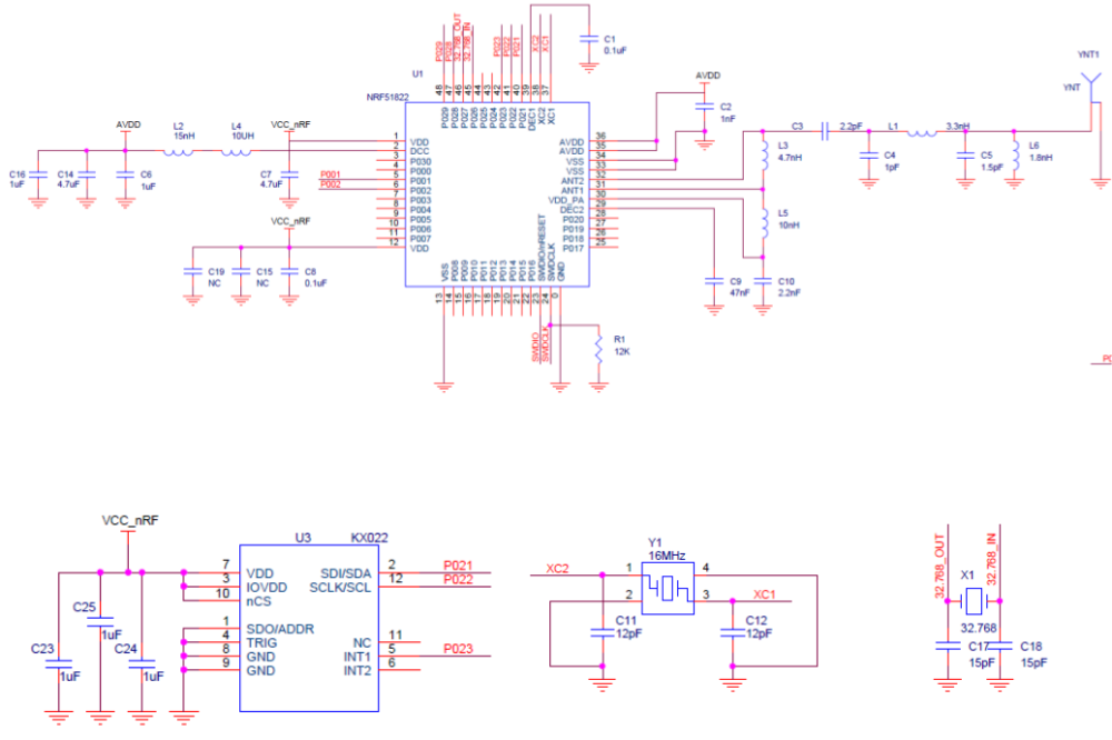
@toyman Correct. You can review the schematic for this project: https://www.openhardware.io/view/472/Ebyte-nRF52832-Prototyping-Board
-
@neverdie thx. Why don't you have a capacitor between DEC4 to GND? I can see only 2 inductors, while Nordic power guidelines prescribe an LC filter between DCC and DEC, ie inductors and a capacitor. nrf52dk also has it.
@toyman I guess I made an error then. Thanks for pointing that out. In general, I haven't gotten much feedback on the PCB's that I've posted, so any feedback is always appreciated. :)
-
@toyman I guess I made an error then. Thanks for pointing that out. In general, I haven't gotten much feedback on the PCB's that I've posted, so any feedback is always appreciated. :)
-
@omemanti said in nRF5 Bluetooth action!:
@neverdie Question is, did the DC/DC still work without the cap?
I believe it did. If you look at: https://www.openhardware.io/view/471/Ebyte-nRF52832-Small-Breakout-Board
which has the inductors soldered on, I believe that is the one that I tested. Enough time has passed though that I can't be 100% sure now. I made a number of different variations, and I didn't post all of them. -
@omemanti said in nRF5 Bluetooth action!:
@neverdie Question is, did the DC/DC still work without the cap?
I believe it did. If you look at: https://www.openhardware.io/view/471/Ebyte-nRF52832-Small-Breakout-Board
which has the inductors soldered on, I believe that is the one that I tested. Enough time has passed though that I can't be 100% sure now. I made a number of different variations, and I didn't post all of them.@neverdie said in nRF5 Bluetooth action!:
nough time has passed though that I can't be 100% sure now. I made a number of different variations, and I didn't post all of them
I used your schematic for a PCB I ordered yesterday :), did saw the post about the cap until it was too late :(
part of the game!Edit: according to your post https://forum.mysensors.org/topic/6961/nrf5-bluetooth-action/797 it did work
-
@korttoma have you tried the code @NeverDie put together using the LPCOMP ? With a QFAAH0 (which I believe is the same version than QFABC0, but with 256K flash) he went down to something like 4µA.
From the document you link, anomaly 70, it will be necessary to add an extra wait of 36us after that line, it's strange that @NeverDie never had any problem with it. Or maybe I misunderstand the document :)void activateLpComp() { ... while (!(NRF_LPCOMP->EVENTS_READY)) {} //wait until ready ... }Test code from @NeverDie using LPCOMP is here:
https://forum.mysensors.org/topic/6961/nrf5-bluetooth-action/1307I will try it on my board (using a module with QFAAH0) tomorrow, if power consumption is as low as expected I'll try on the beacon board.
[Edit] Just checked quickly my "beacon" board and it's using a QFAAH1 chip (made in 2017), so the test might not be relevant...
@nca78 said in nRF5 Bluetooth action!:
I will try it on my board (using a module with QFAAH0) tomorrow, if power consumption is as low as expected I'll try on the beacon board.
@NeverDie I have tried the sketch nearly unchanged (only changed to lines because I use pin P0.01 so AIN2) and my current consumption is a bit over 30uA, do you have any idea of what I should check ? (I tried with both versions 0.1 and 0.3 of MySensors NRF5 boards).
At the moment my board only has a led and a DRV5032FB (<<1uA) in addition to the nrf51 module. -
Just to close the loop on DC-DC:
Figure 2
-
@nca78 said in nRF5 Bluetooth action!:
I will try it on my board (using a module with QFAAH0) tomorrow, if power consumption is as low as expected I'll try on the beacon board.
@NeverDie I have tried the sketch nearly unchanged (only changed to lines because I use pin P0.01 so AIN2) and my current consumption is a bit over 30uA, do you have any idea of what I should check ? (I tried with both versions 0.1 and 0.3 of MySensors NRF5 boards).
At the moment my board only has a led and a DRV5032FB (<<1uA) in addition to the nrf51 module.@nca78 said in nRF5 Bluetooth action!:
do you have any idea of what I should check ?
Have you tried disabling serial?
-
@nca78 said in nRF5 Bluetooth action!:
do you have any idea of what I should check ?
Have you tried disabling serial?
-
Unsure then.
-
@nca78 said in nRF5 Bluetooth action!:
I will try it on my board (using a module with QFAAH0) tomorrow, if power consumption is as low as expected I'll try on the beacon board.
@NeverDie I have tried the sketch nearly unchanged (only changed to lines because I use pin P0.01 so AIN2) and my current consumption is a bit over 30uA, do you have any idea of what I should check ? (I tried with both versions 0.1 and 0.3 of MySensors NRF5 boards).
At the moment my board only has a led and a DRV5032FB (<<1uA) in addition to the nrf51 module.@nca78 said in nRF5 Bluetooth action!:
@NeverDie I have tried the sketch nearly unchanged (only changed to lines because I use pin P0.01 so AIN2) and my current consumption is a bit over 30uA, do you have any idea of what I should check ? (I tried with both versions 0.1 and 0.3 of MySensors NRF5 boards).
At the moment my board only has a led and a DRV5032FB (<<1uA) in addition to the nrf51 module.Ok, case closed, it was just because the SWD pins were still connected to my NRF52 DK. When I just connect VCC and GND it's down to something a bit below 5uA. I'm using a multimeter and DK is at 2.8V so real consumption will be a bit higher. But it should give me a battery life around 1year for my bedroom doors, so I'll just use my nrf51 modules for that and move to the more interesting nrf52.
-
@nca78 said in nRF5 Bluetooth action!:
@NeverDie I have tried the sketch nearly unchanged (only changed to lines because I use pin P0.01 so AIN2) and my current consumption is a bit over 30uA, do you have any idea of what I should check ? (I tried with both versions 0.1 and 0.3 of MySensors NRF5 boards).
At the moment my board only has a led and a DRV5032FB (<<1uA) in addition to the nrf51 module.Ok, case closed, it was just because the SWD pins were still connected to my NRF52 DK. When I just connect VCC and GND it's down to something a bit below 5uA. I'm using a multimeter and DK is at 2.8V so real consumption will be a bit higher. But it should give me a battery life around 1year for my bedroom doors, so I'll just use my nrf51 modules for that and move to the more interesting nrf52.
@nca78 would you mind sharing your sketch files for your door sensors?
As I'm not a programmer and not so good at programing I usually rely on example code to get anything done. More examples gives me more understanding how things should be done.- Tomas
-
@nca78 would you mind sharing your sketch files for your door sensors?
As I'm not a programmer and not so good at programing I usually rely on example code to get anything done. More examples gives me more understanding how things should be done. -
@toyman I guess I made an error then. Thanks for pointing that out. In general, I haven't gotten much feedback on the PCB's that I've posted, so any feedback is always appreciated. :)
@neverdie said in nRF5 Bluetooth action!:
@toyman I guess I made an error then. Thanks for pointing that out.
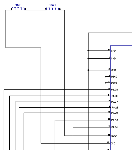
I actually think you were correct in your design, @NeverDie ;-)
A while ago part of the e73-2g4m04s schematic was posted on this forum:
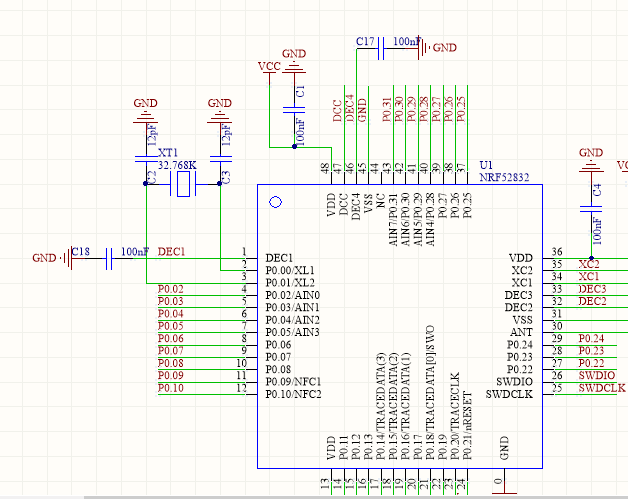
Clearly the inductors to use the DC/DC converter are not connected to DCC. There is however a capacitor C17 from DEC4 to GND.
The Nordic reference schematic shows the missing L2 and L3, but capacitor C10 is actually present in the e73-2g4m04s (the mentioned C17, albeit only 100nF instead of 1.0uF in the reference):
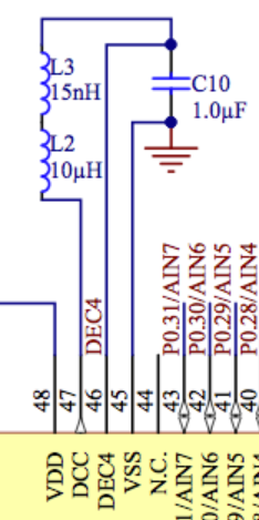
Therefore I think your breakout is correct, as only the inductors between DCC and DEC4 need to be added to match the reference schematic :+1:
http://yveaux.blogspot.nl
-
@neverdie said in nRF5 Bluetooth action!:
@toyman I guess I made an error then. Thanks for pointing that out.
I actually think you were correct in your design, @NeverDie ;-)
A while ago part of the e73-2g4m04s schematic was posted on this forum:
Clearly the inductors to use the DC/DC converter are not connected to DCC. There is however a capacitor C17 from DEC4 to GND.
The Nordic reference schematic shows the missing L2 and L3, but capacitor C10 is actually present in the e73-2g4m04s (the mentioned C17, albeit only 100nF instead of 1.0uF in the reference):
Therefore I think your breakout is correct, as only the inductors between DCC and DEC4 need to be added to match the reference schematic :+1: