What did you build today (Pictures) ?

-
@ncollins said in What did you build today (Pictures) ?:
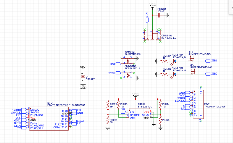
10P 0.5 FPC connector for programming and serial debugging
How many of the 10 pins do you actually use?
-
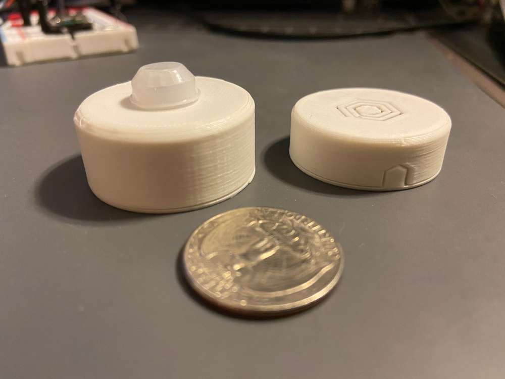
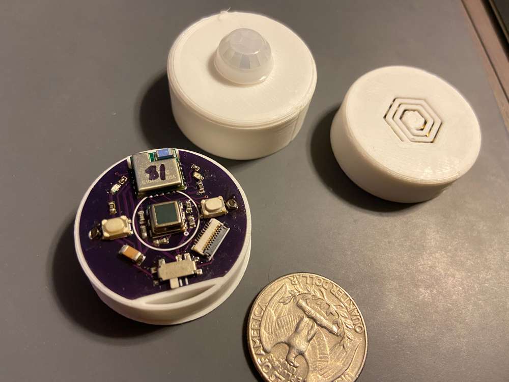
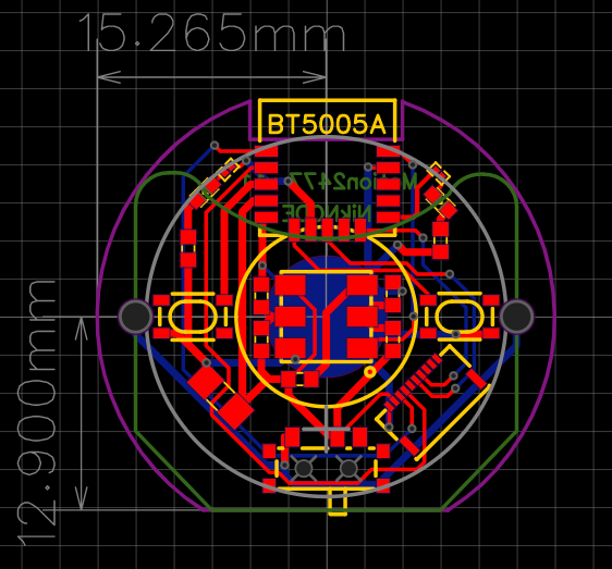
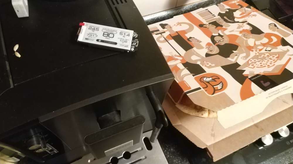
The latest addition to my coin cell nodes, a PIR motion sensor based on the Ebyte NRF52805 module.
The PIR sensor is a Senba S16-L221D-2. I'm measuring around 24uA, which is higher than advertised, but with the 6-7uA from the NRF52805, should still get me 3-4 years on a single 2477.
-
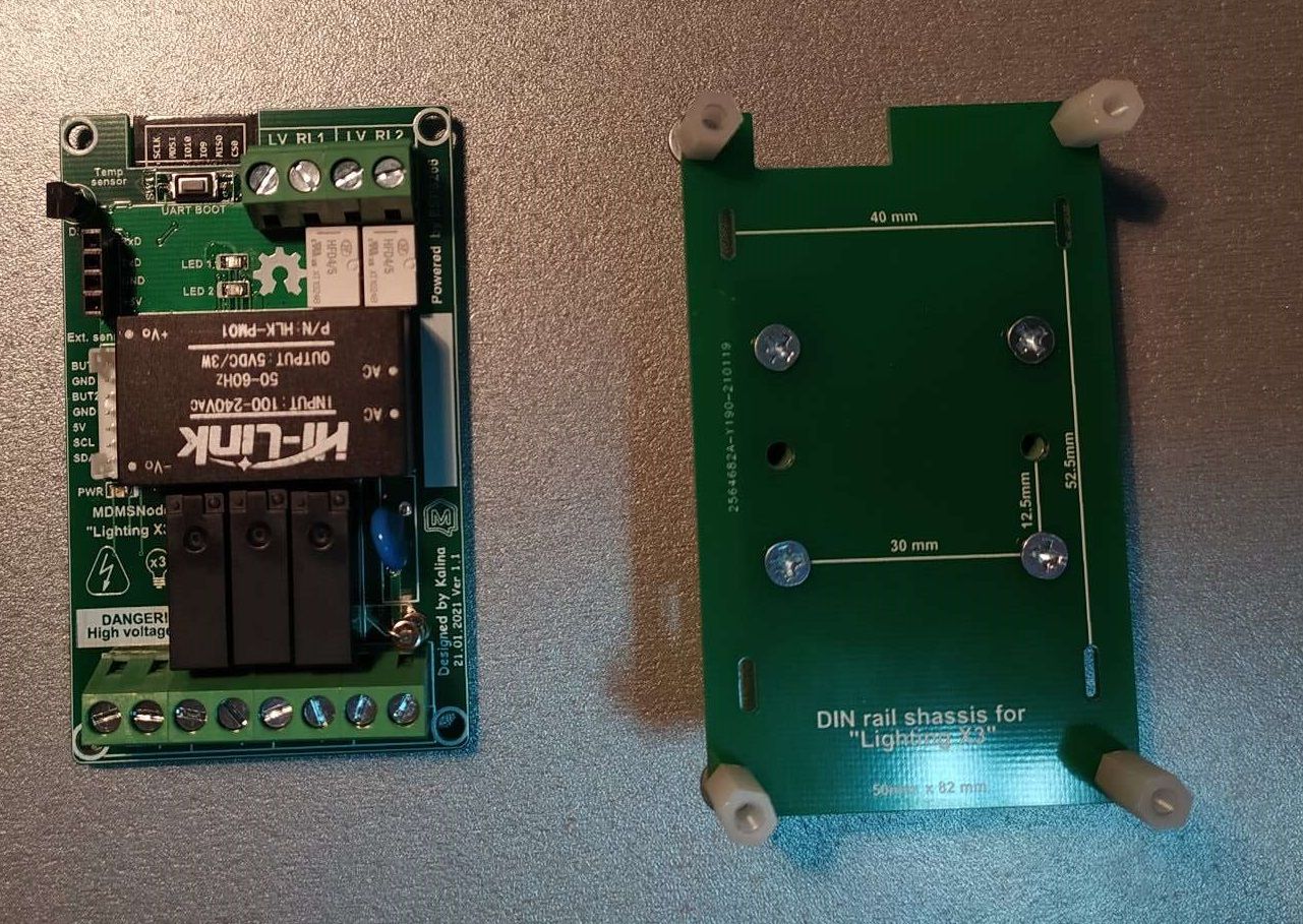
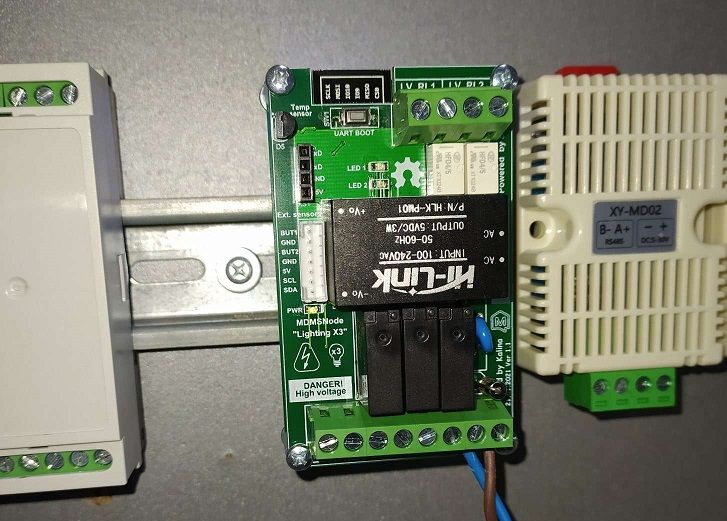
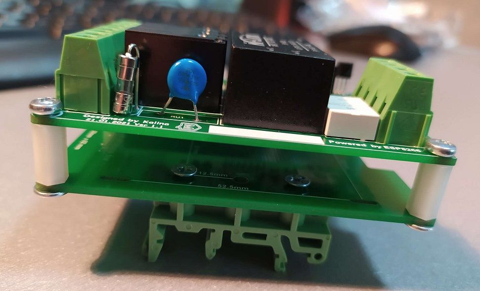
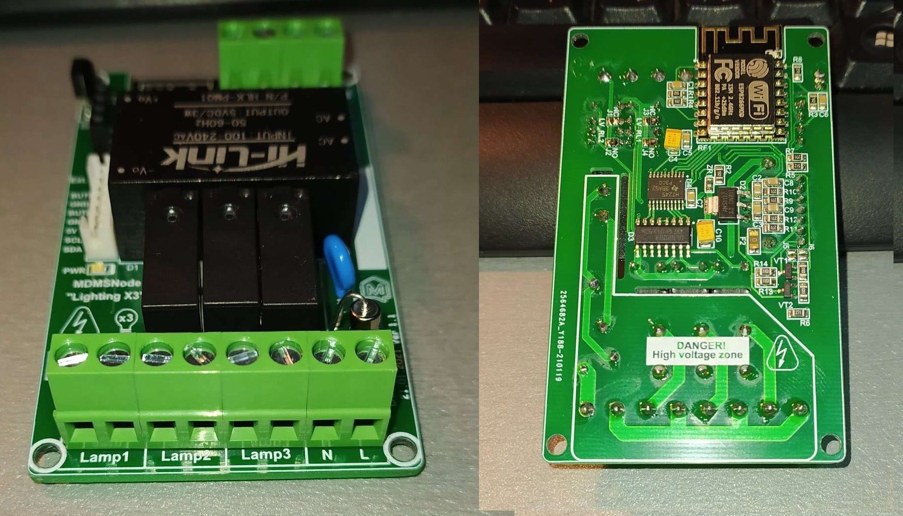
Today i have assembled the latest revision of my Lighting X3 for DIN rail mounting.
-
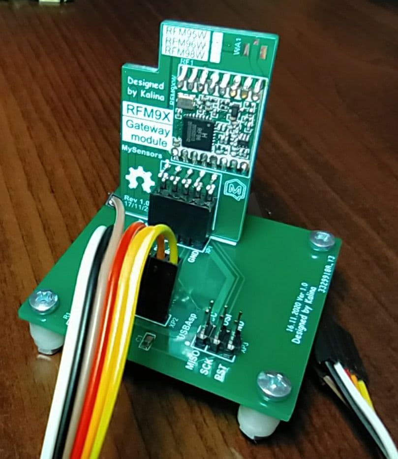
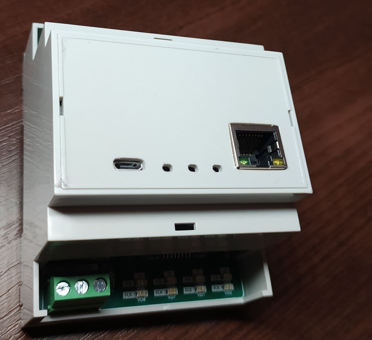
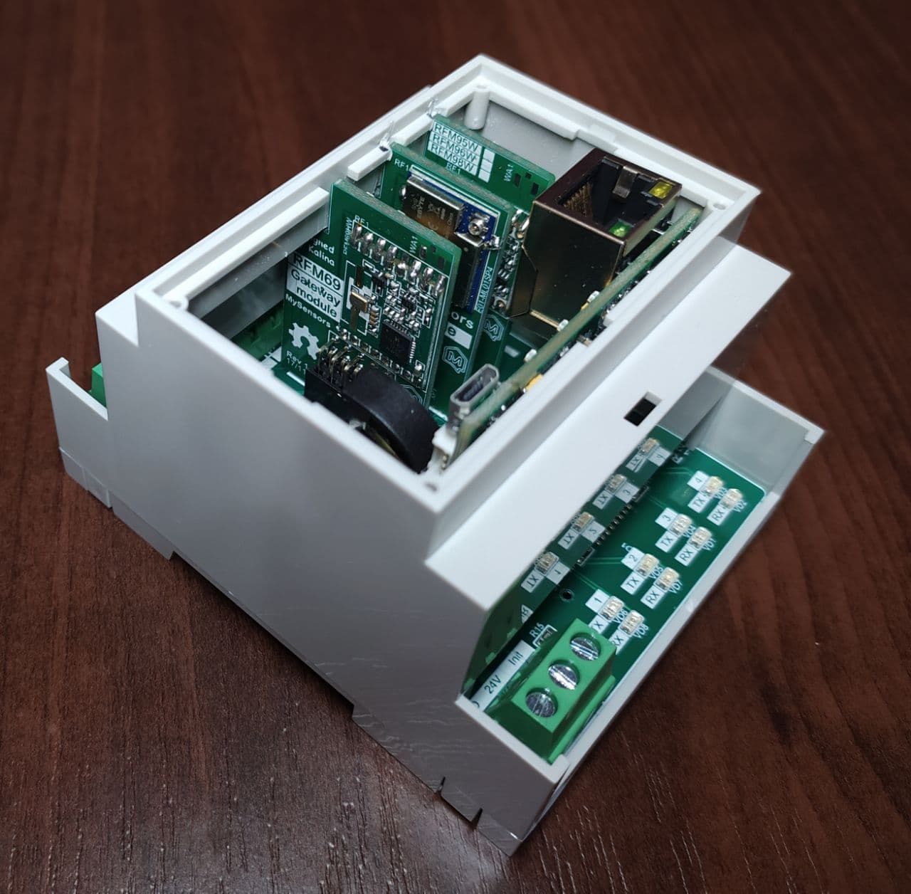
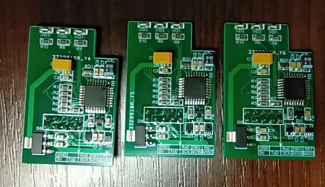
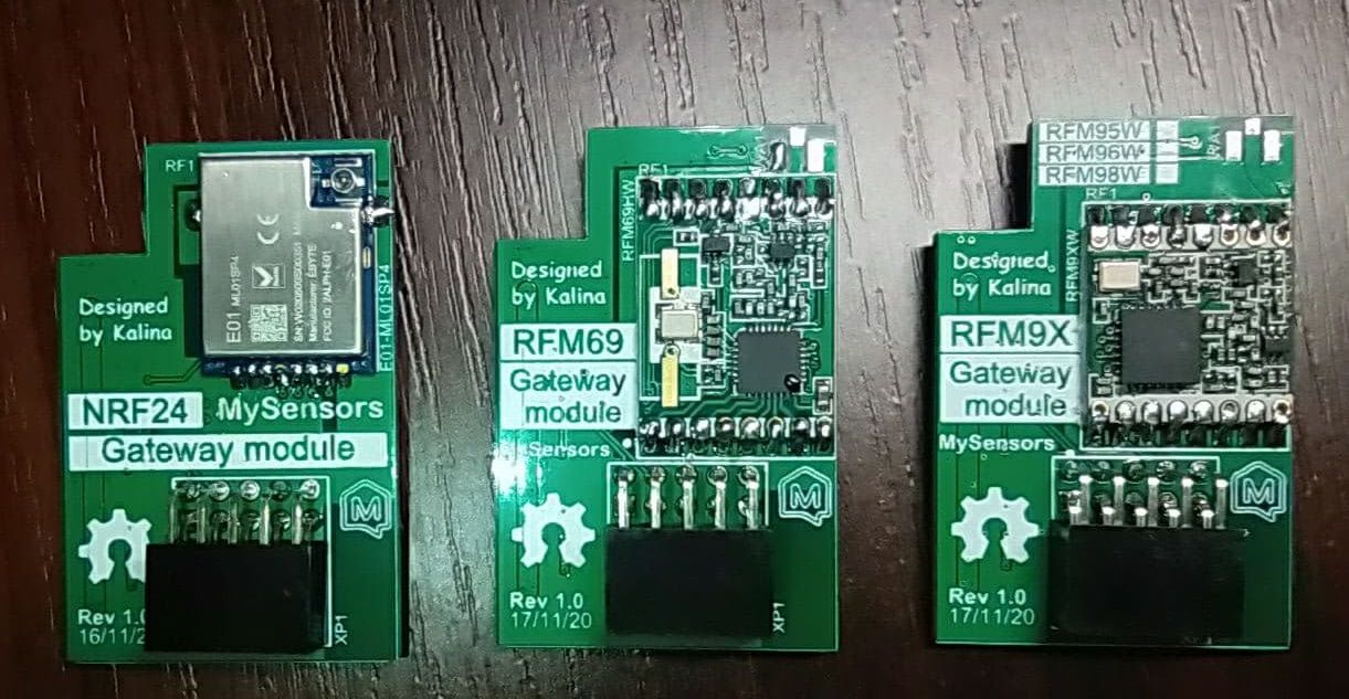
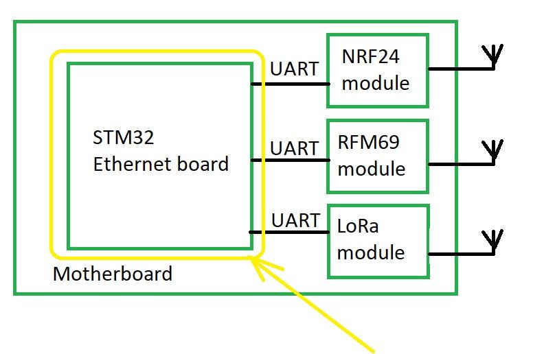
Oh yes, I forgot to share photos of my new project - Multinetwork Mysensors Gateway. The main idea of this gateway is that it can at the same time serve up to four different networks (Lora - RFM9X, 2.4 GHz - NRF24 and ISM band RFM69). These networks can be assembled in separate modules and each user can build own set of modules. The incoming stream will be connected via Ethernet on various ports, for example, the gate will have the IP address 192.168.1.128, and each subnet will be served on ports 5003 - the first subnet, 5004 - the second, and so on ...
-
@monte Not certainly in that way. In this project, everything is open source with the exception of the board with an ethernet (based on STM32). The ethernet board was developed by my partners and they are not ready to share it yet. But I hope I can persuade them to do it :-)
-
@monte Not certainly in that way. In this project, everything is open source with the exception of the board with an ethernet (based on STM32). The ethernet board was developed by my partners and they are not ready to share it yet. But I hope I can persuade them to do it :-)
@kalina I like how it both consolidates and reduces wall-wart clutter all in one stroke. :-)
I don't see any antennas though. Where do they go? And does having multiple radios packed close together like that create any noteworthy EMI? I knew a guy who had set up an RFM69 hat on his Raspberry Pi but later found that the raspberry Pi produced a lot of RF noise/EMI that reduced the effective range of his gateway. I don't know whether or not that might happen in your case, but I thought I'd mention it to help with your troubleshooting in the event you notice any unexpected range reduction.
-
@monte Not certainly in that way. In this project, everything is open source with the exception of the board with an ethernet (based on STM32). The ethernet board was developed by my partners and they are not ready to share it yet. But I hope I can persuade them to do it :-)
-
@kalina I like how it both consolidates and reduces wall-wart clutter all in one stroke. :-)
I don't see any antennas though. Where do they go? And does having multiple radios packed close together like that create any noteworthy EMI? I knew a guy who had set up an RFM69 hat on his Raspberry Pi but later found that the raspberry Pi produced a lot of RF noise/EMI that reduced the effective range of his gateway. I don't know whether or not that might happen in your case, but I thought I'd mention it to help with your troubleshooting in the event you notice any unexpected range reduction.
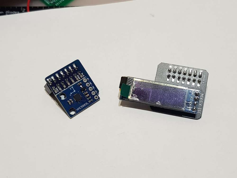
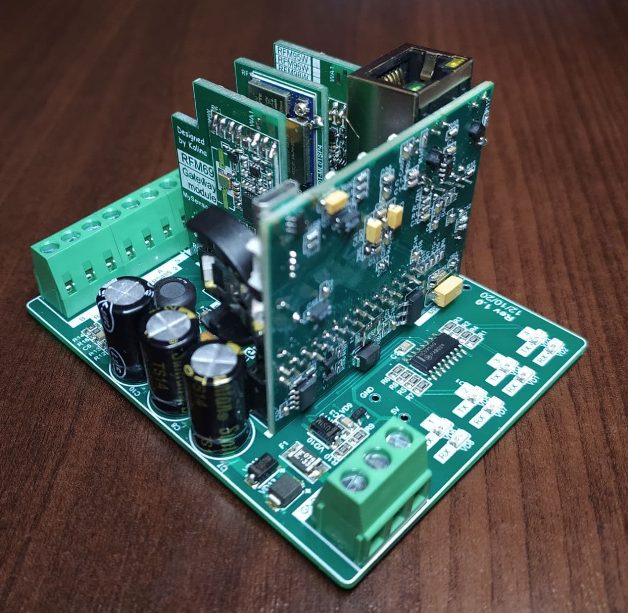
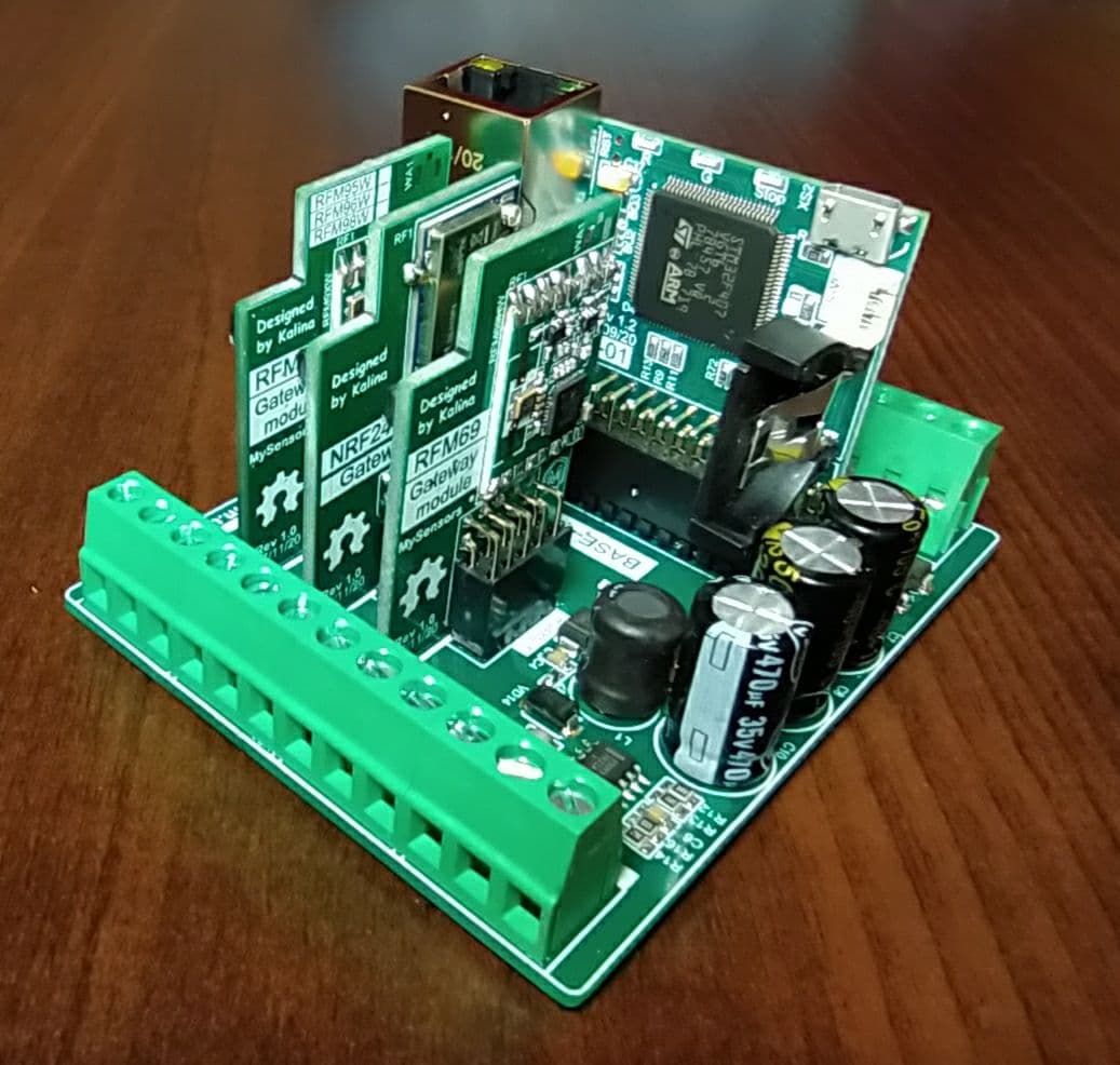
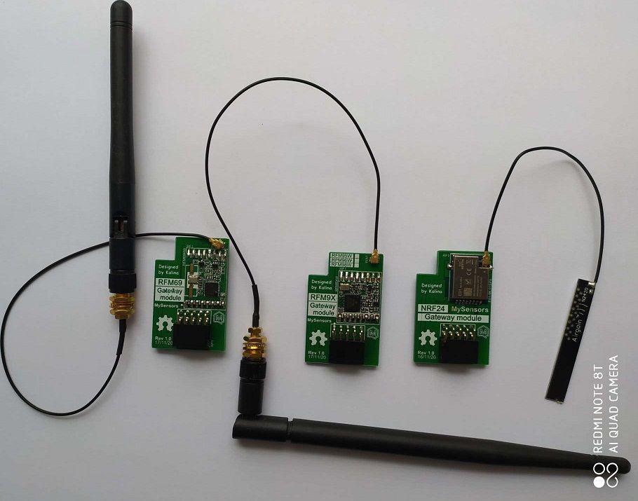
@NeverDie EMI is a big topic. I think there will be no problems. I am going to do some tests of communication
quality for various modules and antennas. As for the antennas, I am going to fixed them to the body through the holes, but I have not yet decided on the location. As for connection antenna to the module you can see the on photo ...
-
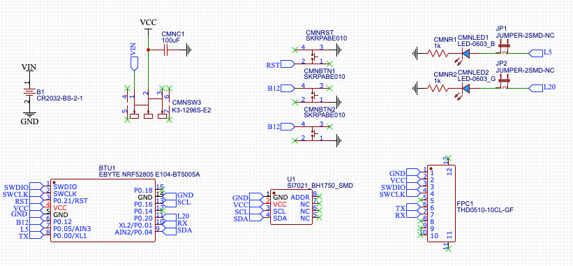
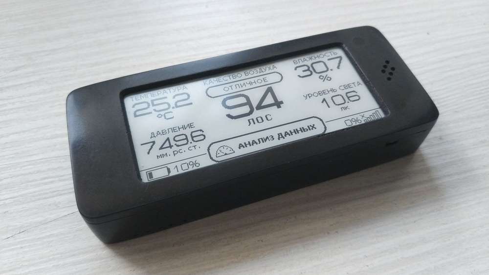
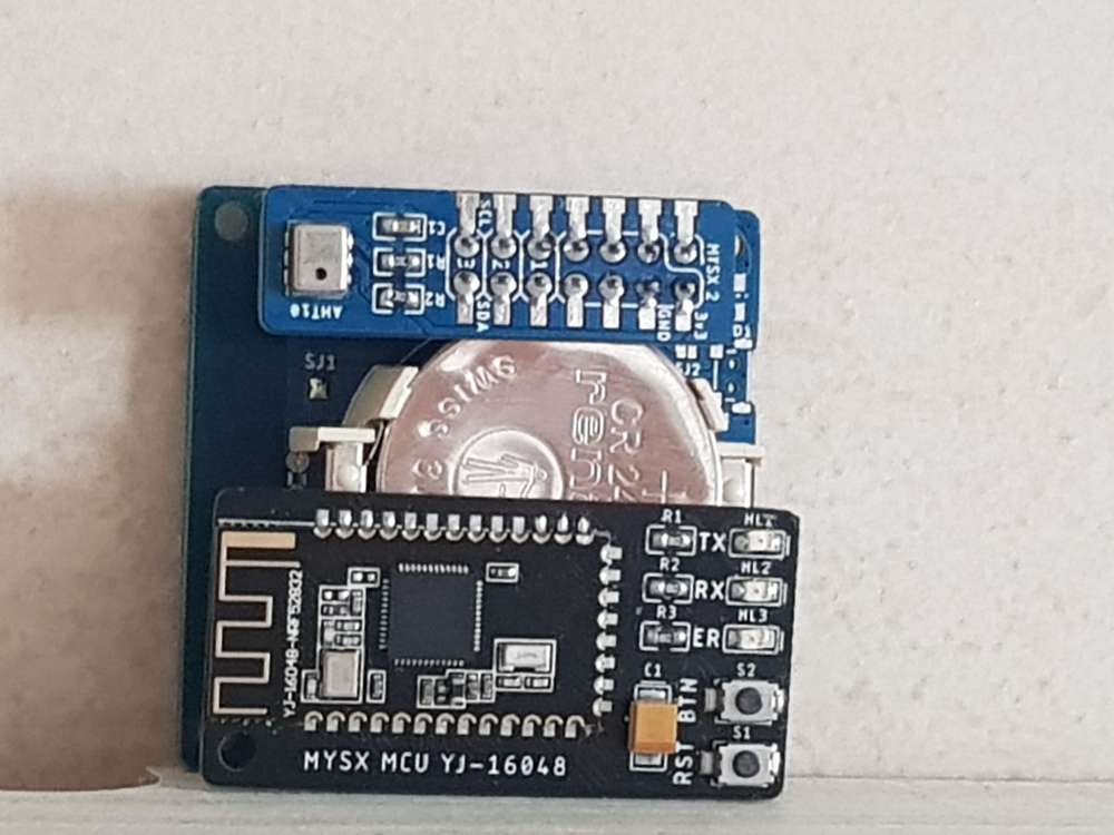
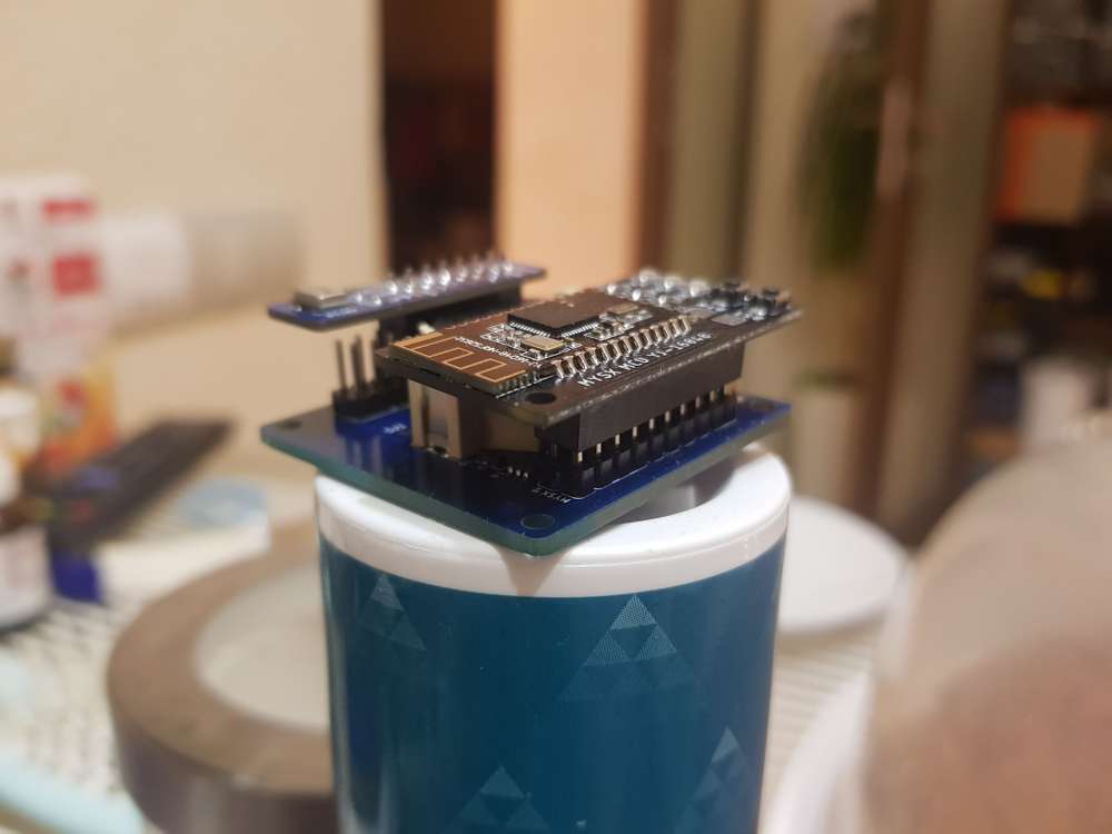
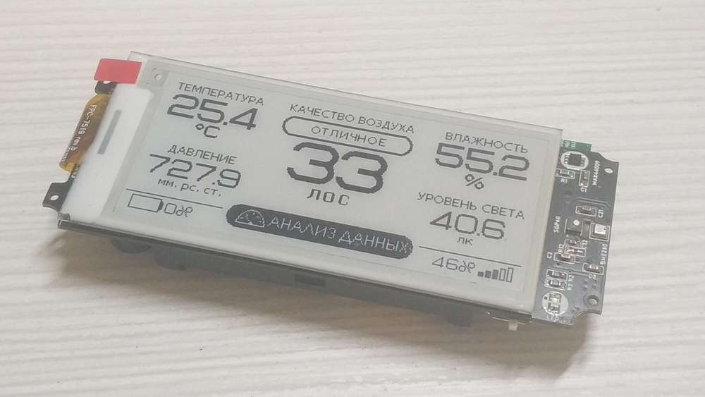
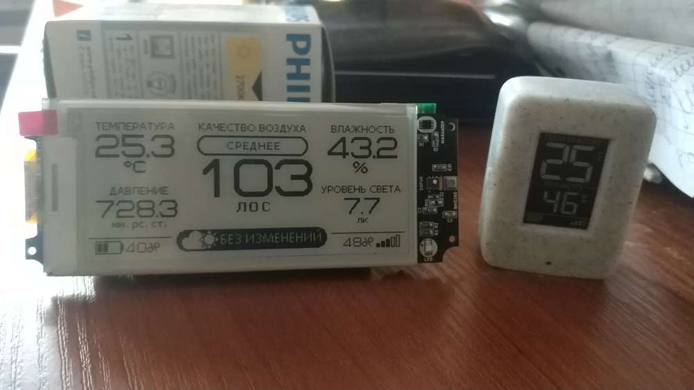
Hello everyone. I want to show you my new device, battery powered air quality sensor. The device also has light, temperature, humidity, and atmospheric pressure sensors. I am currently testing the software.
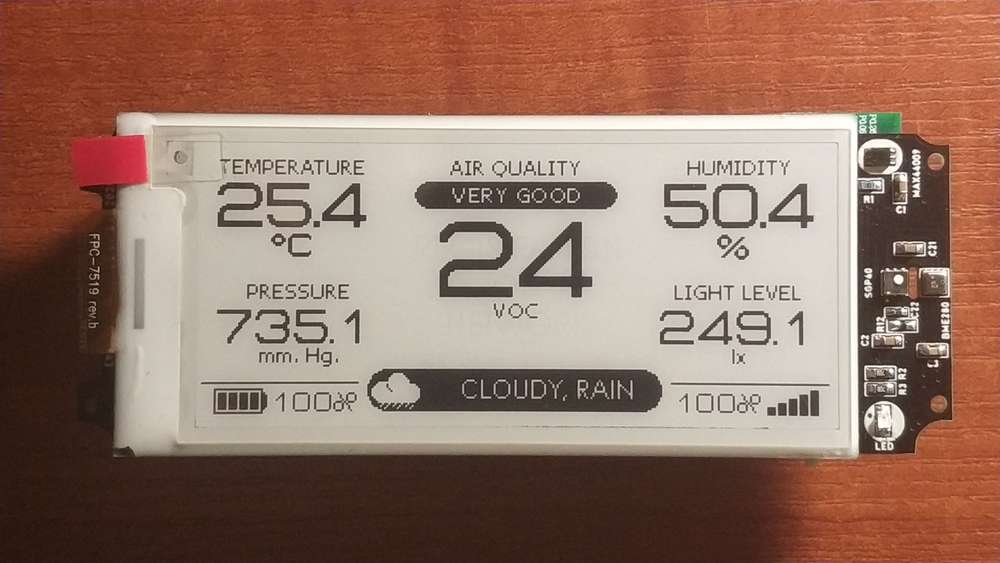
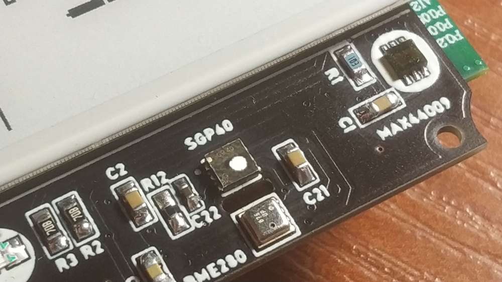
@berkseo I'm curious: which air quality sensor did you opt to build into your device, and what about it did you prefer over the other available air quality sensors that you might have picked, but didn't? Two or three years ago I looked into a few different sensors, but they looked bigger that what you've settled on and their capabilities were pretty narrow. Hopefully the sensor offerings have gotten better since then.
-
Hello everyone. I want to show you my new device, battery powered air quality sensor. The device also has light, temperature, humidity, and atmospheric pressure sensors. I am currently testing the software.
-
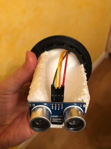
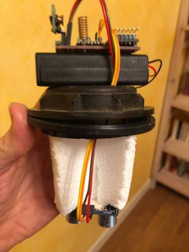
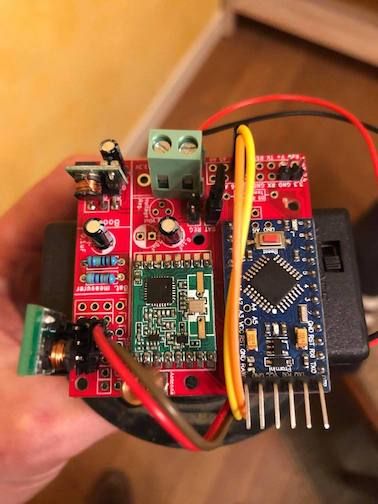
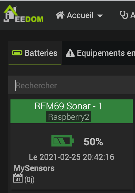
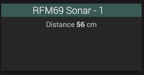
My first RFM69 Battery sensor: an ultrasonic sonar to measure the level of my fuel tank (don't laugh, winters can be cold in Burgundy :-) )
Many thanks to @sundberg84 and @mfalkvidd for advice to the Newbie i am and to @Gerator for the RFM69 gateway
-
My first RFM69 Battery sensor: an ultrasonic sonar to measure the level of my fuel tank (don't laugh, winters can be cold in Burgundy :-) )
Many thanks to @sundberg84 and @mfalkvidd for advice to the Newbie i am and to @Gerator for the RFM69 gateway
-
@mfalkvidd You're right: For production i'm going to build isolation for the sensor not to be in contact
Anyway: The flash point of domestic fuel oil is 55 ° C, which means that fuel oil cannot ignite below this temperature. In addition, in its liquid form, fuel oil is non-flammable at room temperature.
-
Hi guys,
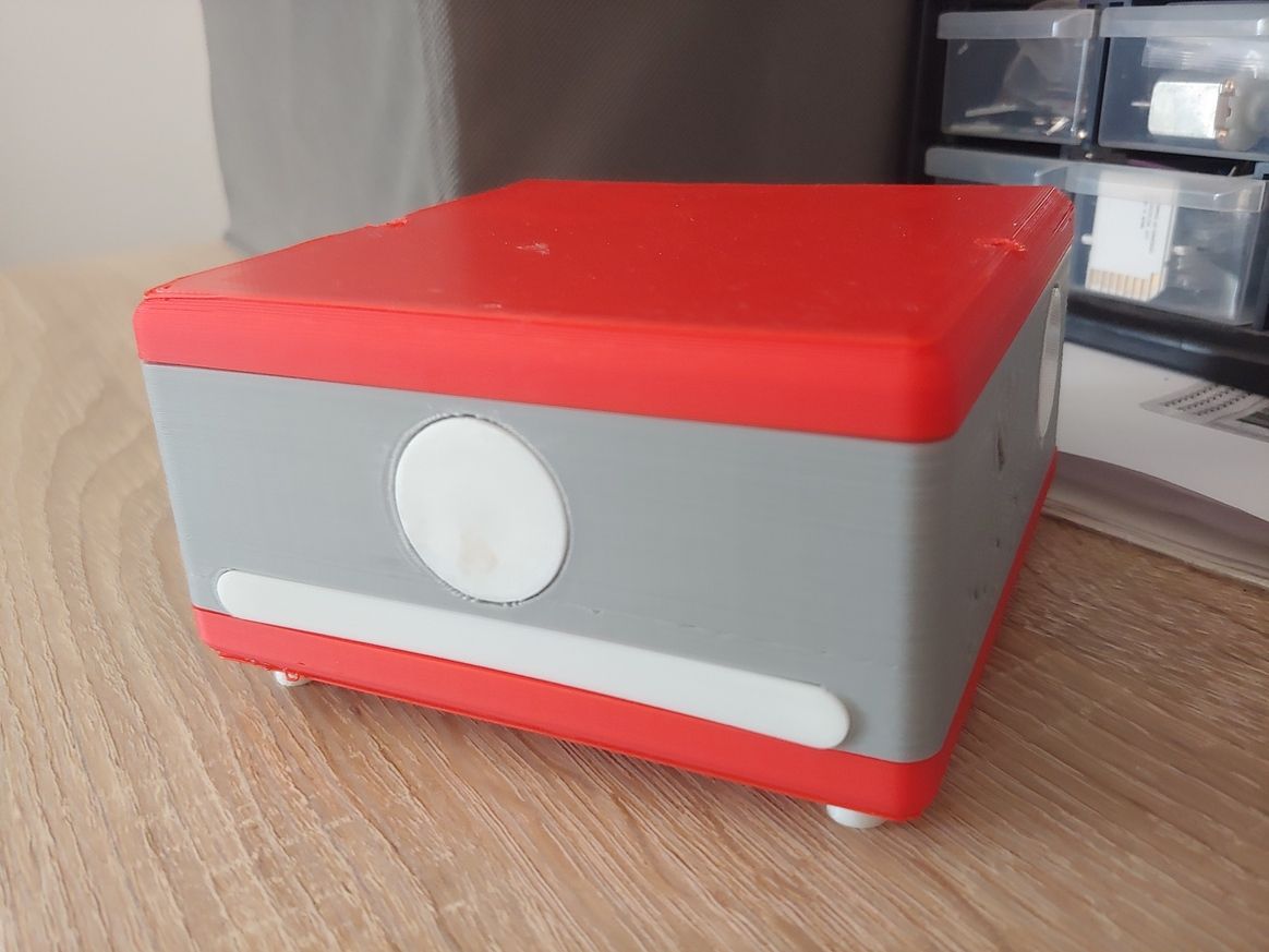
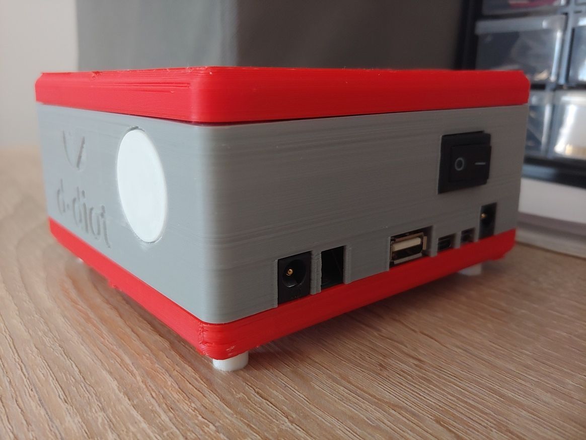
my last creation: the d-diot hub v.3.0
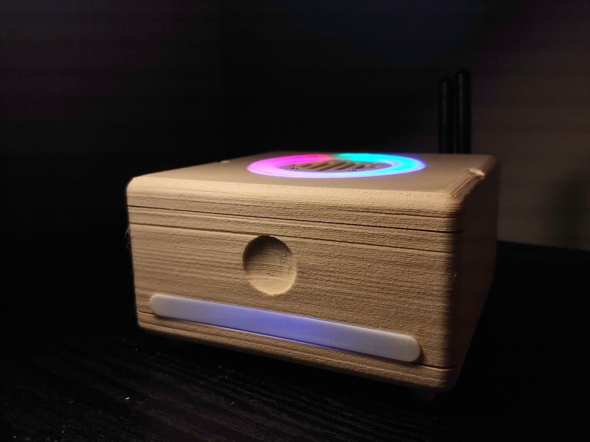
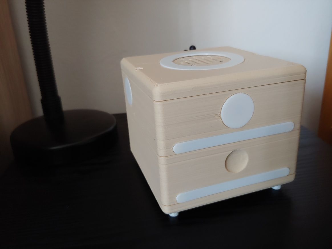
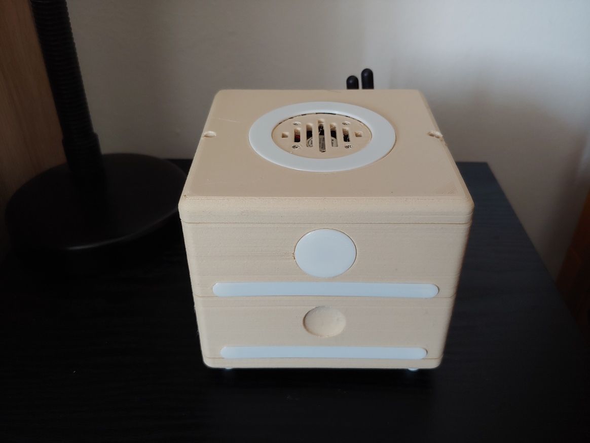
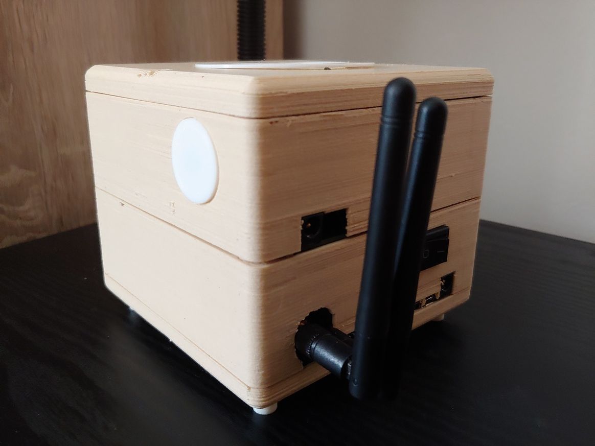
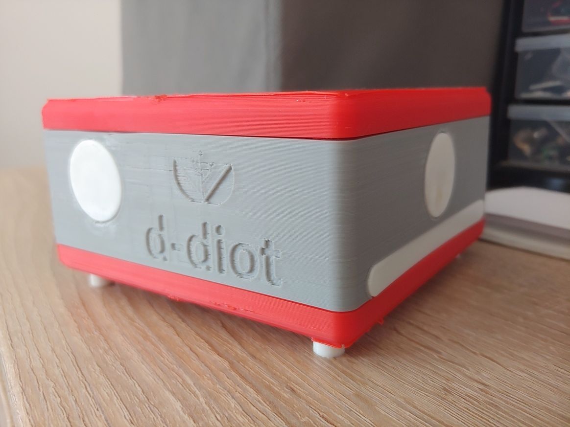
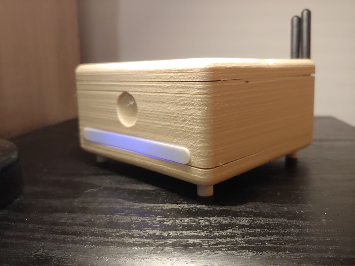
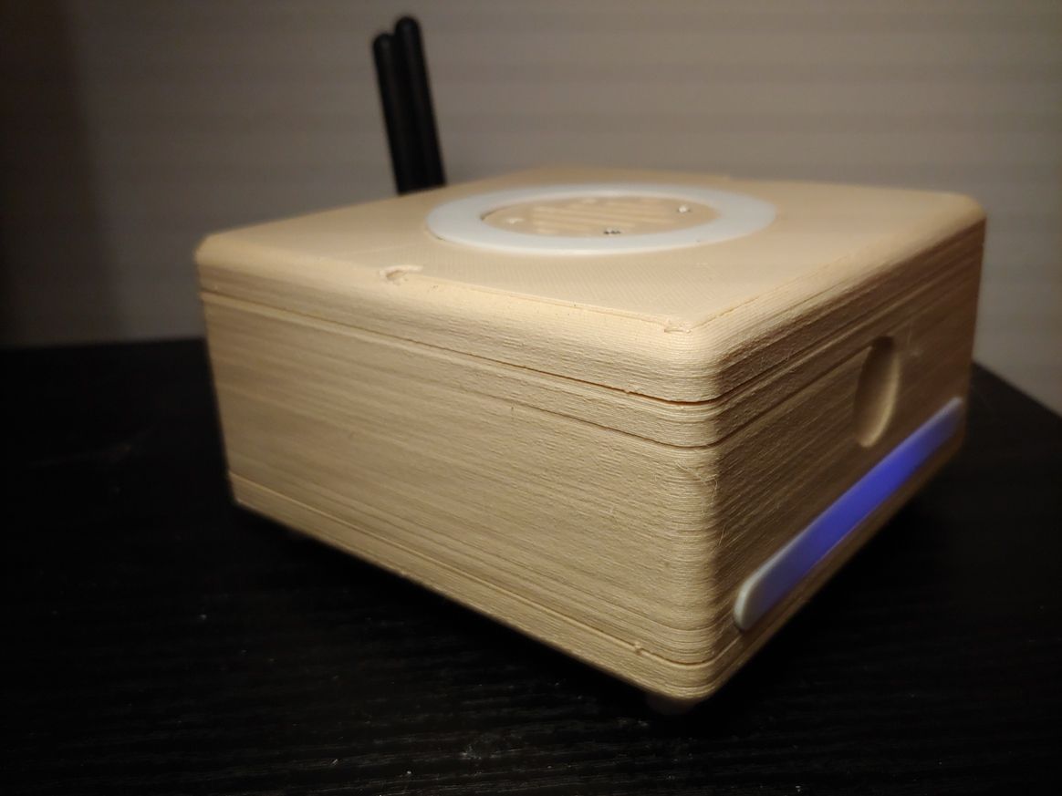
The hub A (wood) is a dual MySensors gateway (RFM69 and NRF24) based on two ESP8266 modules and a BLE gateway + RGB controller thanks to an ESP32 module and ESPHome firmware.
The hub B (grey and red) is an IR gateway and RC 433 Mhz gateway based on ESP32 modules with an ESPHome firmware. The hub B has also an integrated step-up and step-down voltage regulator based on Arduino Nano.
To allow the maximum flexibility in placement inside the house, each module can be build as a stand-alone piece of hardware or combined in a single device (see pictures).
The hub is meant to be used with Home Assistant, the case is 3d printable and as usual, if someone is interested, there is a dedicated wiki page with all the details and the build instructions.
-
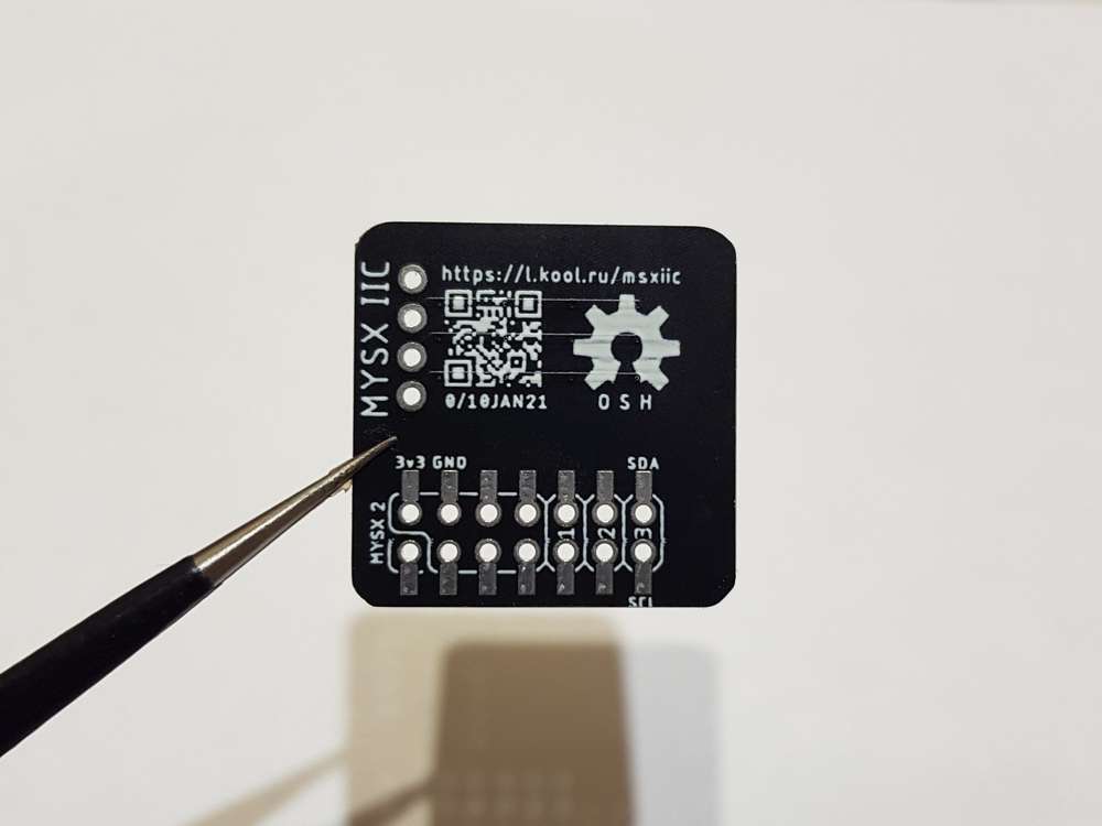
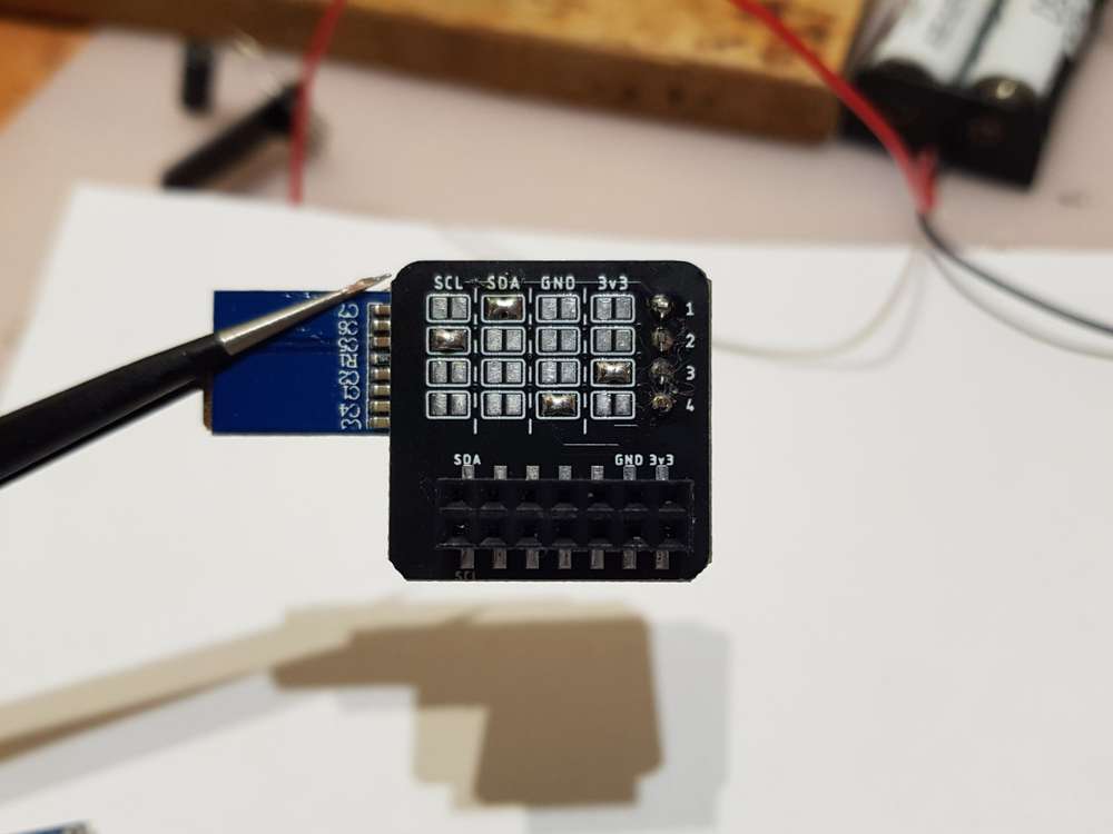
@KooLru - very clever sollution for the lines.