What did you build today (Pictures) ?


  • Mod

    Today I also started upgrading my Domoticz running Raspbian 7 (Wheezy) to Raspbian 9 (Stretch). I tried to do an in-place upgrade but the rpi wouldn't start after the upgrade so I had to start over on a clean Raspbian 9 image.

    I took the chance to switch to f2fs for the root filesystem, which should make the SD card less susceptible to corruption. I used this guide and it worked, except that I also added discard to the fourth field in /etc/fstab and changed the sixth field to 0 to not fsck before boot.

    When I wake up tomorrow, domoticz might have finished compiling.


  • Though not directly MySensors related, I am setting my 3D printer up with some lights to see my prints for my MySensors projects better when running a job. These are some white LED light assemblies that have been salvaged from some recycled document cameras. I built a simple 7805 regulator circuit to run them. The next step is to design and print some brackets and articulating arms to mount them to the printer.
    0_1510472883445_upload-624321fb-df7a-41d4-a54f-1b8337715289
    0_1510472909796_upload-ad6d9514-19ea-43dd-91ce-87e302af64f5 0_1510472927556_upload-0332836f-c3ef-4256-9df9-60c6f6980b28


  • MySensors Evangelist

    @mfalkvidd ai ai. Yes. I was warned on the Domoticz website about the 'not being able to startup'. I was able to successfully update from Wheezy to Jessi. Skipped the Stretch part for now.

    Just made some preparations for the new node that has to replace several individual nodes in the technical-room. (Control of WTW, Measurement of heating pipes of CV using Temperature Sensors, Leakage Detector of CV, Door Sensor and last but not least OTGW-Reset)
    0_1510504350773_What_i_did_today-resized.jpg

    Could not complete the PCB due to some missing components. The Sketch is running fine on my NANO
    0_1510504673338_Proto-resized.jpg
    Looks like a mess now, but this development PCB comes in quite handy.


  • Hardware Contributor

    That was yesterday.. 😊

    @tekka and I tested some new features he made, so here was my humble and fun test setup

    0_1510566539991_IMG_20171112_203729.jpg

    Of course the Halo GW didn't disappoint us! All boards (mixed mcus and radios nodes) were attacking it at an agressive rate (100ms rate), and there was no crash at all. Halo GW was laughing & kidding us saying "Please give me more, I like doing this" 🙂 (but I was lazy to assemble more, there was 13 nodes on the table..).
    Too strong @tekka 😉


  • Hero Member

    Here is my Wemos "Serial" wireless gateway that I just today put together and installed. Connects to Domoticz as an ethernet gateay over wi-fi. Uses a static IP address that I configured on the wi-fi router. By the way, it's powered (and physically supported) by an Ikea USB charger, as seen in the photo. 🙂
    0_1510588567991_Wemos_gateway.jpg


  • Mod

    0_1510868791579_IMG_20171116_224416.jpg

    Mqtt IR remote controller for air conditioning / heat pump

    0_1510868927908_Screenshot_20171116-224308.png

    Quick interface design using Mqtt dash

    Not mysensorized, but still a neat and cheap solution.


  • Hero Member

    @gohan That would make for a very interesting project write-up, so that others might quickly replicate your work without a lot of head scratching.


  • Mod

    It is actually very simple project: I followed this guide -> http://www.sysrun.io/2017/02/22/use-a-esp8266-to-control-your-ac-via-mqtt/ and used a pn2222a to boost the IR Led.
    Also the app is very simple: just link each item to one of the topics.
    It was meant to be a simple stand alone solution, connected to an external mqtt broker so you can turn on heating/cooling before coming back home without using any complex Home automation system. It is still in the test phase as I just have the IR led transmitting something and I have to test if it is actually working with the Daikin unit I need to control (it is not in my house so I have to way for the real test)


  • MySensors Evangelist

    0_1510959314040_Dallas Working.jpg
    With help of @dbemowsk @sundberg84 I was able to complete my "CV All in one sensor" using the easy PCB. 😉
    It now replaces 2 Arduino Nanos with only 1 Easy PCB. Currently the 0,1u Capacitor is missing, however as I was told by the designer it still could work. And it does.

    This node:

    • monitors the pipes of my central house heating,
    • Is able to detect if the heating unit has a leakage.
    • Switches on the light if the door is opened
    • if the humidity in the bathroom becomes to high, or somebody is cooking.. It will start the BRINKS central WTW.
    • Can reset my OTGW unit if it has a lock up.

    0_1510959911977_Vloerverwarmin.JPG


  • 4x cheap load cells under each foot of my bed
    0_1511141720759_2017-11-19 17.33.49.jpg

    Sparkfun HX711 breakout and an Arduino
    0_1511141724939_2017-11-19 17.33.58.jpg

    Was going for a bed occupancy sensor, but I got a pretty decent scale out of it, it is sensitive enough that it registers if I put my water bottle down on the bed.


  • Hardware Contributor

    @SquareKinematics said in What did you build today (Pictures) ?:

    Was going for a bed occupancy sensor, but I got a pretty decent scale out of it, it is sensitive enough that it registers if I put my water bottle down on the bed.

    Sounds awesome if it's that precise, could you make a post in "My Project" with reference to the load cells you used, wiring and some test code ? Thank you in advance 🙂


  • @Nca78 I will be sure to do that when it's done, it's still a little rough around the edges 🙂


  • Hardware Contributor

    Today I made a pogo pin programming board for my Logger. (The logger works except one last thing... Rev 5 here we come!)
    0_1511353120457_15113530928851279978681.jpg


  • I've been playing with an Adafruit AudioFX board and cobbled together this annunciator. Eventually it will be a MySensors node to play alarms or other sounds. It is using a cheap portable speaker to play the sounds. I got it to work with my doorbell button node today.
    annunciator test


  • Hardware Contributor

    Last fix done on my Logger... I will send it to pcb house today and probably publish a beta on openhardware. Probably nothing special but for me as hobby pcb maker this has been a challenge and great knowledge increase in using oscilloscope and new components.

    0_1511440593878_15114405675621084714349.jpg

    Tomorrow Black Friday!! (I work in retail so that's a high focus now...)


  • Hero Member

    Yesterday received the PCB. Today assembled for testing this battery-powered nRF52-based passive infrared motion detector:
    0_1511459187973_PIR_02.jpg


  • Mod

    Battery powered MySensors Washing machine & dryer monitor, using LDR's to monitor LEDs on front of the appliances.
    Each time a LED toggles, the node wakes from interrupt and sends a message. Easy peasy!
    When a device is ready, I'll get a message on my mobile phone 😄

    0_1511607742913_upload-656fdf4c-6707-4a8b-a58c-ef7e74fe1b9f

    0_1511607798459_upload-0183f0a1-571d-45e6-8ecc-b4a33fd9c4e9

    Still need to stuff it in an enclosure...


  • Mod

    @Yveaux said in What did you build today (Pictures) ?:

    Still need to stuff it in an enclosure...

    Yes, definitely very low WAF 😁


  • Hardware Contributor

    @gohan - you mean HIGH waf? 🙂 I really like the design... (if the first picture is only what you see)


  • Mod

    @sundberg84 said in What did you build today (Pictures) ?:

    @gohan - you mean HIGH waf? 🙂 I really like the design... (if the first picture is only what you see)

    Ofcourse! WAF is overrated anyhow...


  • Hardware Contributor

    @Yveaux - Yes, as long as you don't tell her 😉


  • @Yveaux
    I think I have similar washing machine, doesn't the LED blink if leave the laundry inside the machine after it had ended washing?
    Just curious, if you anyway have had the lid/cover removed from washing machine, why not solder wires parallel to LED and connect to an optocoupler that feeds signal direct to Arduino, and also take 5V supply from the washing machine, and then you can avoid using batteries


  • Hardware Contributor

    @bjacobse it's pretty different to remove the top that's usually easily removable to put inside furniture, and to unmount front panel and then solder stuff on the PCB. High WAF probably includes ensuring the warranty is not void 😄


  • Mod

    @bjacobse said in What did you build today (Pictures) ?:

    @Yveaux
    I think I have similar washing machine, doesn't the LED blink if leave the laundry inside the machine after it had ended washing?

    The sensor is placed on a led that lights when the machine is finished. I would prefer a led that is lit when it is washing and goes out when finished, but my machine hasn't any.

    Just curious, if you anyway have had the lid/cover removed from washing machine, why not solder wires parallel to LED and connect to an optocoupler that feeds signal direct to Arduino, and also take 5V supply from the washing machine, and then you can avoid using batteries

    Now I simply removed the cover to hide the wire. The electronics and led are hidden behind a lot of metal aan plastic. I didn't want to take the washer apart and the dryer too.

    Just a simple solution working for multiple devices.


  • @Yveaux said in What did you build today (Pictures) ?:

    @bjacobse said in What did you build today (Pictures) ?:

    @Yveaux
    I think I have similar washing machine, doesn't the LED blink if leave the laundry inside the machine after it had ended washing?

    The sensor is placed on a led that lights when the machine is finished. I would prefer a led that is lit when it is washing and goes out when finished, but my machine hasn't any.

    Just curious, if you anyway have had the lid/cover removed from washing machine, why not solder wires parallel to LED and connect to an optocoupler that feeds signal direct to Arduino, and also take 5V supply from the washing machine, and then you can avoid using batteries

    Now I simply removed the cover to hide the wire. The electronics and led are hidden behind a lot of metal aan plastic. I didn't want to take the washer apart and the dryer too.

    Just a simple solution working for multiple devices.

    Ah this make good sense, I didn't think the electronics was hidden and difficult to get to


  • Mod

    @bjacobse said in What did you build today (Pictures) ?:

    Ah this make good sense, I didn't think the electronics was hidden and difficult to get to

    It's German quality 😏


  • Finally got my LoRaWAN RAk831 with RPI gateway online


  • @Yveaux So I never fully understood the reasoning behind putting sensors on a washer or dryer. So you start your clothes washing or drying before you leave for somewhere. Is there a reason to know that it's finished when you are away? There is nothing you can do about it until you get home, at which time you could reasonably assume that it is finished. If you are home, can't you just go and check it after some time? Why would you need a message on your phone?

    Just curious.


  • Mod

    @dbemowsk just to keep the machines running continuously 😉
    And I need to go up 3 stairs to just check on them 💩


  • @Yveaux Makes some sense. Another reason would probably be....."Because you can"... LOL


  • Hardware Contributor

    @dbemowsk said in What did you build today (Pictures) ?:

    @Yveaux So I never fully understood the reasoning behind putting sensors on a washer or dryer. So you start your clothes washing or drying before you leave for somewhere. Is there a reason to know that it's finished when you are away? There is nothing you can do about it until you get home, at which time you could reasonably assume that it is finished. If you are home, can't you just go and check it after some time? Why would you need a message on your phone?

    Just curious.

    Or if someone else than you starts the machine before leaving for the full day, and you come back much earlier and if you don't have a warning you don't necessarily think about checking the washing machine when you arrive home. Here with the warm temperature if I leave the laundry in the washing machine for 4-5 hours without opening, I'm good for a new wash because it will smell pretty bad 😞


  • @dbemowsk
    My wife actually fairly often forget to check when the washingmachine is finished, and notice it a few hours later, when kids are a sleep and there is quiet in the house, I will imagine receiving an SMS when washing machine is ready to be emptied will help her, as she is checking her phone often,, even when kids are using all her time


  • Hero Member

    The value on a dryer is even more tangible: the sooner you get your clothes out, the less wrinkly they get.


  • @NeverDie All good points that I hadn't thought of.


  • MySensors Evangelist

    @dbemowsk while you are at it..consider 🙂

    The dishwasher can be added as well. My devices dishwasher / washing machine / dryer send messages to all tvs that are turned on. Identifying themselves and invite you to come and clean them :). It comes in handy and absolutely jaw dropping on your visitors.

    If you turn on the stove air circulation system in the kitchen... Why not greet the wife with automatically start the TV in the kitchen and play her favourite radio channel at her preferred volume...


  • Hero Member

    Back to the OP topic, I made a micro-usb OTG cable (bottom cable below) that passes through all 5 pins:
    0_1511722883854_OTGcable.jpg
    This will replace the more fragile cable above it in the next generation of my nRF5 micro-usb programming/debug adapter.

    It turns out you can't buy this cable. At least, I couldn't find any for sale. Instead, I had to make it myself. Fortunately, Adafruit sells a little DIY kit that helped tremendously:
    https://www.adafruit.com/product/1826

    🙂


  • Mod

    @NeverDie So much heat shrink tubing -- makes my eyes hurt 😭


  • @NeverDie So many colours of nations offended... Have you thought of going for President ?


  • Hero Member

    Actually, this was the very first time I've used shrink tubing. How could I do it better?

    Mostly I didn't want there to be much bending, which might lead to tearing loose the solder connections. I wanted the finished cable to be a "once and done." Now that it's done, the connections should go very easy.


  • 0_1511727705490_15117276954701212117694.jpg

    0_1511727729141_15117277179511389767526.jpg

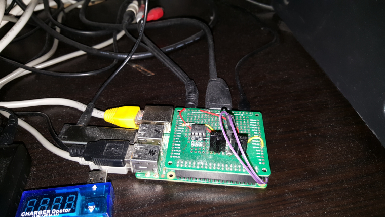
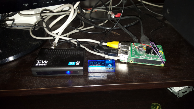
    I use raspberry for watching television, movies etc. Today I build raspberry hat to turn on from remote control. Attiny85 recognizes programmed remote code and by optocoupler short circuit on pins.


  • @scalpel how do You program the ir code for the power button ? can it be programed from the linux running in the rpi ? or it is just hardcoded into atiny code ?


  • Hardcoded In attiny. Learn arduino irremote library.

    Pozdrawiam / regards


  • @scalpel yeah, I did this kind of project also and I wonder if there is a software for that 🙂 It would be fun to be able to set the wakeup ir code from the linux os, with for example i2c or 1-wire interface.


  • Mod

    @rozpruwacz how often would you need to change the IR code for that?


  • rarely, but still it would be fun to make such thing 🙂


  • @sincze said in What did you build today (Pictures) ?:

    her favourite radio channel at her prefer

    @sincze hi, could you elaborate a bit more the TV messages, do you have any link with more info? Was that the LG tv with Mqtt that was mentioned on the forum?(or I mixed forums)


  • MySensors Evangelist

    @dakipro we use kodi on al lgl tvs. The libreelec TV box has cec and can turn on the TV via hdmi. If TV is on I am able to control the volume via the LG webserver. Kodi (api) can display the notifications for Me :). Not that fancy but it works like a charm.


  • Side note. I did a quick search, there is a cec library for arduino!
    https://github.com/stefslon/cec-arduino


  • @sincze
    If it works like a charm - it's fancy 😉


  • Hardware Contributor

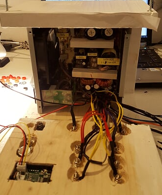
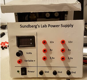
    Back to topic! Last night I made some changes to my ATX Power supply because the variable settings was to sensitive:

    0_1511953574080_upload-c7feca62-d22d-435e-9c73-9599ca0c9044

    0_1511953586756_upload-3bb65a38-91b8-4dc8-9dd7-3a0af6fd45f9


  • @sundberg84 Did you find that taking the cover off improved the accuracy at all ?
    😆


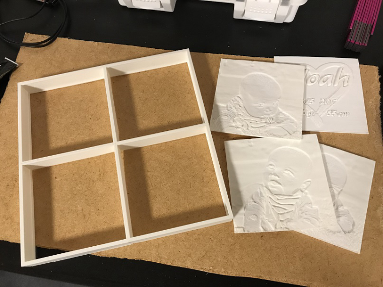
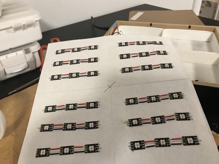
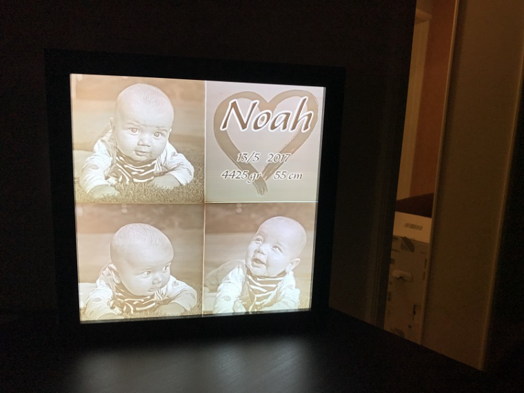
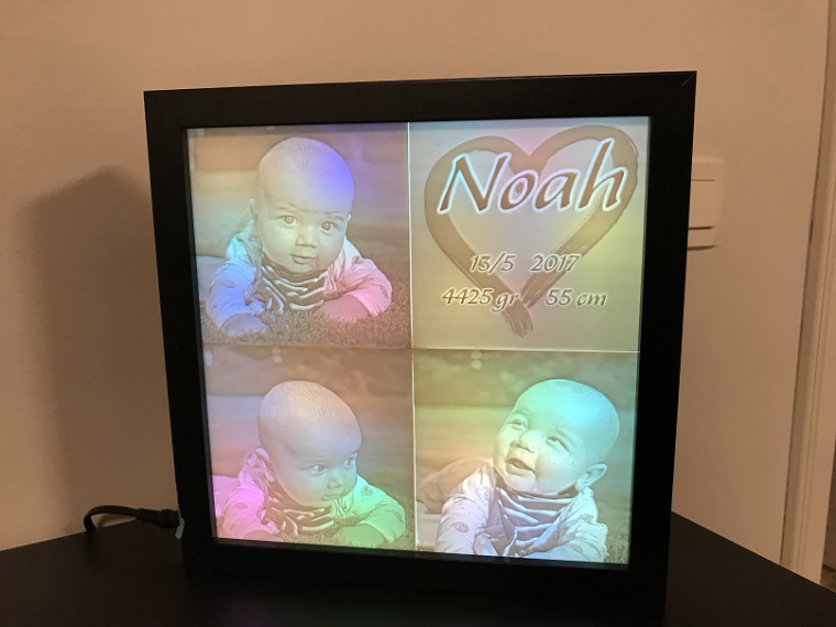
  • I built a lithophane lamp for my grandson. The electronics is basically only a pro mini and 36 neopixels. Sadly this version is not mysensorized but maybe I'll do that in version 2 🙂

    0_1511962986127_IMG_8296.jpg
    0_1511963011727_IMG_8301.jpg
    0_1511963026597_IMG_8297.jpg
    0_1511963045498_IMG_8298.jpg


  • Hero Member

    @maghac Cool. How were you able to convert the photos into that embossed material (or whatever it is)? Is that a CNC process, or something else? It seems to have very good resolution.


  • Mod

    I have seen a video where you can convert your pictures and print them using a 3D printer


  • @gohan said in What did you build today (Pictures) ?:

    I have seen a video where you can convert your pictures and print them using a 3D printer

    Correct, these are 3D printed lithophanes (https://en.wikipedia.org/wiki/Lithophane). I used http://3dp.rocks/lithophane/ to convert jpg files to STL files for printing.


  • Hardware Contributor

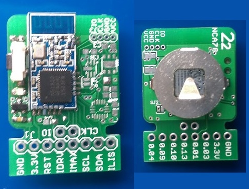
    After failing to assemble a completely functional version of my new livolo switch board, I assembled a first prototype of my new "22" sensor board. Unfortunately I didn't receive the sensors yet so it only has a switch, a hall sensor for door and a led, but that's enough for the first testing.
    Board is made to cut headers when it will be finished, but meanwhile I can use the headers to make it a breakout board for the nrf51 module or for each of the sensors.
    0_1512127797656_22.jpg


  • Hardware Contributor

    @Nca78 nice 👍 it looks like familiar to me, i don't know why 😉 I agree with you, I prefer rounded square shape as it fits more easily everywhere than circles


  • Hero Member

    👍 Have you settled yet on what kind of connector you're going to use on future boards?


  • Hardware Contributor

    @scalz said in What did you build today (Pictures) ?:

    @Nca78 nice 👍 it looks like familiar to me, i don't know why 😉

    Not sure which one you're talking about, as it's some kind of child between @NeverDie 's board (same nrf51 module and small size) and your aeos (shape, on board sensors). But it's more like a challenge to me, make the smallest board possible (22*22mm) with as many sensors as possible (at the moment, door, TH, light, accelerometer) and I have a bit of margin to add more like the leak detection from @NeverDie it's really nice to be able to do it with such a tiny sensor.
    I'll do a more complete and flexible 33 board later, I will try to make it some kind of a hand-solderable version of aeos 😉


  • Hero Member

    As far as minimizing size goes, I think you're right: square (or some kind of rectangle) is going to be better. I end up throwing away a lot of useable space going from square to circle, which, unfortunately, forced me into increasing the diameter (i.e. the size). So, in the end, square/rectangular is probably better. 🙂 I think the allure of the circle is to try to fit the whole thing perfectly onto a coincell (which acts as a kind of limit on how small you can ultimately go), but unfortunately that can't happen with any of the coincell holders I've seen so far....


  • Hardware Contributor

    @Nca78
    It was just a private joke 🙂 If I inspire some people, then I'm glad! Because like you said, aeos is different (better mcu, more ios&sensors, and latest unpublished revision is..more generous).

    But, if you're trying to make a "aeos" (same sensors for instance) in future, then i don't get the point..why reinventing the wheel? Your board has qfn/dfn footprints too, so I don't see how it's easier to handsolder.
    If this is related to Ic's price, there are lot of different ways to get them cheaper.

    You should maybe use stencils (maybe you already do it) that will save your day 😉

    Keep the good work

    @NeverDie yep, agree with you


  • Hero Member

    @scalz We're not going to get much software being written (such as, for instance, an OTA booloader that we can all use or cool self-destructing crypto wizardy) until there's worthwhile nRF5 hardware available, so anything you can do to speed up the release of your designs would really help. I've been trying to Johnny Appleseed this, without getting much apparent traction on people adopting it. People seem to like your stuff, which looks very professional. If you can, try to make it available so people can start writing software, integrating it, etc. As the saying goes, a rising tide lifts all boats. 🙂


  • Mod

    @NeverDie said in What did you build today (Pictures) ?:

    I've been trying to Johnny Appleseed this,

    What have you been trying to do? 😅


  • Hero Member

    @gohan said in What did you build today (Pictures) ?:

    @NeverDie said in What did you build today (Pictures) ?:

    I've been trying to Johnny Appleseed this,

    What have you been trying to do? 😅

    I posted a lot of nRF5 PCB's hoping that others would find some appealing and jump on the nRF5 bandwagon, but so far not much seems to have happened. Aside from some helpful feedback/suggestions from @nca78, I'm not really any better off than if I hadn't bothered. I'm not sure what motivates other PCB posters, but the feedback/suggestions have been the only real payoff for me. Unfortunately, most PCB postings have garnered zero, even if there appear to have been a lot of downloads.


  • Mod

    @NeverDie @scalz To get the nRF5 series adopted by MySensors and its users I think we should start with a single board. We have to make sure it is easy to obtain/replicate (by using a ready available module, or using a hardware partner where people can just order the board) and supply the required getting started docs.
    I really appreciate all the work done on the nRF5 support, but now we have to take the leap from prototype to 'production' to get it adopted by the community.


  • Mod

    @Yveaux agreed
    @NeverDie don't let you down, not everybody knows how to design PCBs or provide suggestions in that matter.


  • Hero Member

    @Yveaux said in What did you build today (Pictures) ?:

    @NeverDie @scalz To get the nRF5 series adopted by MySensors and its users I think we should start with a single board.

    I think that's a good idea. A standardized reference platform would really help in building some forward momentum. How about you start a thread saying exactly what it is that you'd want the board to be like, and maybe it will gather some consensus and someone will make it. Like I say, I've launched numerous trial balloons, and it's just not an efficient way to get there from here. My guess is it will be some kind of multi-sensor board, maybe even the same as what @scalz and/or @nca78 are already doing.


  • Hardware Contributor

    @scalz said in What did you build today (Pictures) ?:

    @Nca78
    But, if you're trying to make a "aeos" (same sensors for instance) in future, then i don't get the point..why reinventing the wheel? Your board has qfn/dfn footprints too, so I don't see how it's easier to handsolder.

    Bigger board won't have those QFN and LGA footprints of course 😉
    As you say I don't want to reinvent the wheel, especially one that'll look square compared to yours 😄
    But I think it's important we still have a DIY option available for those who don't like soldering LGA or 0402, an equivalent of using the pro mini for the nrf5 world.


  • MySensors Evangelist

    This sunday a friend of mine and I did not know what to build. So we decided to use a project designed by @Yveaux
    Source

    I received 2 new CDEByte antennas that needed a range test. As I live in a mansion.... Next to a park we figured out that walking 1 degrees outside would be an excellent time to do a range test. It was not raining so.....

    Our conclusion would be:

    • Cheap ass NRF... good enough for indoor usage.. if it can mesh.
    • Cheap ass Amplified NRF.. good enough in the house, needs a bit more space and power, but works quite well.
    • CDEByte... not cheap.. but man my hands were freezing outside due to the long range.. And according to @Yveaux we could achieve a higher range if we would have set the power to MAX... During testing this was MIN.

    0_1512323585357_cdebytetest.jpg


  • @sincze said in What did you build today (Pictures) ?:

    CDEByte

    Thank you for the test 🙂 Which pointed to me that I urgently need a new serialgateway and use CDEBYTE


  • Over the weekend I hacked the previously battery powered Minecraft lights in the Minecraft bedroom (doesn't everyone have one?). Now there's no more replacing batteries and OpenHAB controls include On, Off, Brightness and Flame Flicker.

    This is the reason I was asking about establishing power distribution in the attic. I've decided to distribute 12v and drop to 5 or 3.3 only as needed.

    More info and video: https://techconz.com/smart-home/minecraft-lights/

    alt text
    alt text


  • Hero Member

    Received the PCB today, so I put together this leak detector for testing:
    0_1512430579892_leak1.jpg
    0_1512430601719_leak2.jpg
    Looks as though some of the physical clearance tolerances are a bit tight, so I'll have to do another spin after changing the PCB layout. Some Kapton tape will compensate for now and allow for some initial testing.


  • Not MySensors, but related. Power over Ethernet (802.3af compliant) addon for the raspberry pi zero. I plan to use this for high power & high reliability devices where wireless will not work.

    Top one is a higher power version, bottom one just uses an off the shelf regulator.
    0_1512445820284_2017-12-04 19.44.55.jpg

    Currently these just have some IR LED's to control IR devices.


  • Hero Member

    @SquareKinematics
    Very useful to have. Not sure if you're aware, but you can buy PoE power adapters off the shelf. Even Amazon sells them. You select the output voltage you want with a slide switch.


  • MySensors Evangelist

    And so it it almost Christmas...

    Jolly jolly.. wel actually no....

    We have had wet feet from the central heating system serveral times now around Christmas or New Year.
    Causing a wet floor and other possible disasters. Yes I know.. A Central Heating Mechanism should not leak, you could try putting a bucket underneath... But that is not 'that home automation' smart that I was looking for.

    So to detect a leakage.... I came up with this some time ago.

    Pretty standard, a few wires... a Mysensors Node... and Pushover to send me urgens notifications about the leakge.

    0_1512750844649_Leakage.jpg link url))

    And ladies and gentlemen it actually works as you can see in the pushover sreenshot, it kicked off today.


  • Hero Member

    @sincze You could also put some salt into your tray for added conductivity when things get wet.


  • MySensors Evangelist

    @neverdie Great tip, this will resolve in even a quicker response during a flood right?. I already added toilet paper as cover for a smooth moist/water distribution. Lets add some salt to that and hopefully never see an error message again. But I wont bet a bitcoin on that ;-).. Happy with this cheap solution.


  • Mod

    well, since you are not using distilled water, normal tap water should have enough conductivity


  • @sincze How did you design the detection circuitry? Are you using an analog or a digital input?

    Tap water should work without adding more conductivity - in my case I just designed something similar but I wanted to detect an overfill of osmosis water, which is similar to distilled. I had issues with getting it to work through a digital input, so I just built a voltage divider capable of detecting the small change in conductivity. I also added a capacitor to be sure that no false alarms would be received because of noise in the lines. It's been working perfect for days now.


  • @neverdie said in What did you build today (Pictures) ?:

    @sincze You could also put some salt into your tray for added conductivity when things get wet.

    Be very careful using salt,i killed an SI7021 doing something similar.
    I got up one morning and found the sensor covered in white fur and it was dead☹


  • 2 gang EU type livolo customisation, from theory to product... still in progress.

    2_1512829925723_small_20171112_011444.jpg 1_1512829925723_small_20171101_175752.jpg 0_1512829925722_small_20170114_124152.jpg 2_1512829936757_small_20171119_155004.jpg 1_1512829936757_small_20171118_202738.jpg 0_1512829936757_small_20171112_011725.jpg !


  • 0_1512830079874_small_20171119_155404.jpg 0_1512830092134_small_20171119_163354.jpg 0_1512830107562_small_20171119_163849.jpg 0_1512830119867_small_20171119_164745.jpg 0_1512830130032_small_20171119_165717.jpg 0_1512830150237_small_20171203_092353.jpg 0_1512830159490_small_20171203_163658.jpg 0_1512830169403_small_20171207_194213.jpg


  • Hero Member

    @andrew Wow!


  • MySensors Evangelist

    @manutremo As the water indeed is 'rock' solid here in the area I was pretty succesfull using the digital pins. A short... when there is a water connection or open... when there is no connection. No false alarms. Only legit... Each leakage costs me money to get some guy to fix it for me. But at least the floor is not ruined anymore as I had that the first 2 times.


  • MySensors Evangelist

    @rmtucker ai ai . what happened with the salt???


  • MySensors Evangelist

    @andrew Wow indeed.


  • MySensors Evangelist

    Almost Christmas, that means... Lights. In this case programmable 5v LED's that are driven by an Arduino and controlled via Mysensors & Domoticz.

    0_1512836207823_WhatsApp Image 2017-12-09 at 17.14.55.jpeg

    While the arduino sketch has a lot of tricks (showing animations).. I still have to figure out HOW I can stop an animation from playing when I want to see the next one.. It now completes the first animation.. and then starts the one I selected. It needs to break from the function if a new message comes in. I'll have to look for some examples in the forum.


  • @andrew I see that You put the nrf module between two pcbs. Do You have issues with reception ? Because the boards may act as a shielding.


  • @rozpruwacz I try to avoid filled copper areas, which could act as RF blockers. as I mentioned, everything is still in progress, in-wall tests will just come. hopefully I'll have time for that in the next 2 weeks.


  • Mod

    (CNC milling forked to separate thread. It got too interesting 🙂 )


  • Hardware Contributor

    @andrew

    I know that this is not the right place to ask but I'm very curious how do you overcome the fact that in EU there's only the live with in the walls for light switches. I saw that you used a HLK-PM0xx module for testing which needs both live and null. Or maybe your "in-wall" wiring is different... Anyways congratulations for your work so far.


  • @mtiutiu well, that's the dirty hacking part 🙂 electricians will probably not like it.

    so, for first, I've a different approach to control my lamps compared to other in-wall switches and dimmers, due to the fact, that I won't switch the mains directly, with the switch. I have LED ceiling lamps which operate at 12V, but the power supplies (230V to 12V) are in the lamps' body. it could be possible to switch their mains on/off thus to turn the lamps on/off (this is what I do now with standard switches), but it is not possible to dim the lights this way.
    to be able to dim the LEDs as well I'll have a lamp controller node right after the switching PSUs in each lamp. this will be controlled with the in-wall switches (and could be controlled with other nodes/gateways as well), over the air only.

    as all of my wall lamp switch have dual wiring (one line in, two switched line out) I planned the following setup:
    one switched line will be "re-assigned" and wired to N at the lamp. this way, at the wall switch I'll have both L and N. the other switched in-wall line will still forward the L to the lamp, but it will do it directly, to continuously operate the lamp's PSU, which also powers the lamp's controller module.
    the controller will be always on and it will control both the dimming (PWM on the 12V) and the switching wich basically allowing or disabling the 12V from the PSU to the LEDs.

    the in-wall switch will be basically just a radio remote controller this way, but operating from the mains, without any need of batteries.

    I hope that my explanation wasn't too complicated 🙂


  • well today finally i decide to change to c.h.i.p. as a controller with domoticz an amazing device but too bad for the product that got really bad customer support, ( if you planning to buy a c.h.i.p. read the forum first to get all the problems)

    this is my controller using a chip, arduino nano

    0_1512877583590_IMG_20171209_213652.jpg
    0_1512877592331_IMG_20171209_213710.jpg

    planing to chage the nano to a nodemcu


  • Hero Member

    @fernando-alvarez-buylla Is the C.H.I.P. better than a Raspberry Pi Zero? At least with a Pi, you know there's going to be support.
    https://www.adafruit.com/product/2885?gclid=EAIaIQobChMIrMm-lcv-1wIVxSSBCh1PJQB3EAQYASABEgItsvD_BwE
    https://www.adafruit.com/product/3400


  • @neverdie go for the pi zero chip is really nice a little better than the pi zero wifi and bt integraded 4gb and a few cool stuff , but theres people that pay a year ago and still waiting for the chip to arrive , no reply and no support on forum , to me chip is dying , you cant never go wrong with a pi , but i will try in a few months the omega2 to remplace my chips


  • Hardware Contributor

    @fernando-alvarez-buylla said in What did you build today (Pictures) ?:

    i will try in a few months the omega2 to remplace my chips

    What kind of controller are you going to run on that underpowered thing ? Entry level price is cheap but if you want SD card reader and a bit more storage (32Mb) you have to pay 20$, more than the price of an orange pi zero + box which is already available and runs well with Armbian.


  • Hardware Contributor

    Working on clearing up the backlog of unfinished NModule shields, today I finished to test the dual touch button shield, made a script to use it as on/off button or as dual button with short press = on and long press = off, as seen below as a dual scene controller.
    https://www.youtube.com/watch?v=064Jlx2eawI

    I made a box so it can be easily customized depending on what you use it for. Unfortunately internet is too bad at the moment in Vietnam to use Fusion 360 so I made it with 123D Design which is less convenient and it's not really high-end assembly 😄

    0_1512964810931_IMAG2085.jpg
    0_1512964835281_IMAG2084.jpg


  • Hero Member

    @nca78 said in What did you build today (Pictures) ?:

    I made a box so it can be easily customized depending on what you use it for.

    Is it a 3D printed enclosure then, or did you find some other way to make it? Looks very nice.


  • Hardware Contributor

    @neverdie said in What did you build today (Pictures) ?:

    @nca78 said in What did you build today (Pictures) ?:

    I made a box so it can be easily customized depending on what you use it for.

    Is it a 3D printed enclosure then, or did you find some other way to make it? Looks very nice.

    3D printed. Bottom of prints can look pretty good if find the good settings and print on a glass surface.


  • @nca78 I would assume that pads 1 and 2 are capacitive touch surfaces, correct? very nice design.


Log in to reply
 

Suggested Topics

  • 4
  • 5
  • 9
  • 3
  • 2
  • 933

1
Online

11.2k
Users

11.1k
Topics

112.5k
Posts