What did you build today (Pictures) ?

-
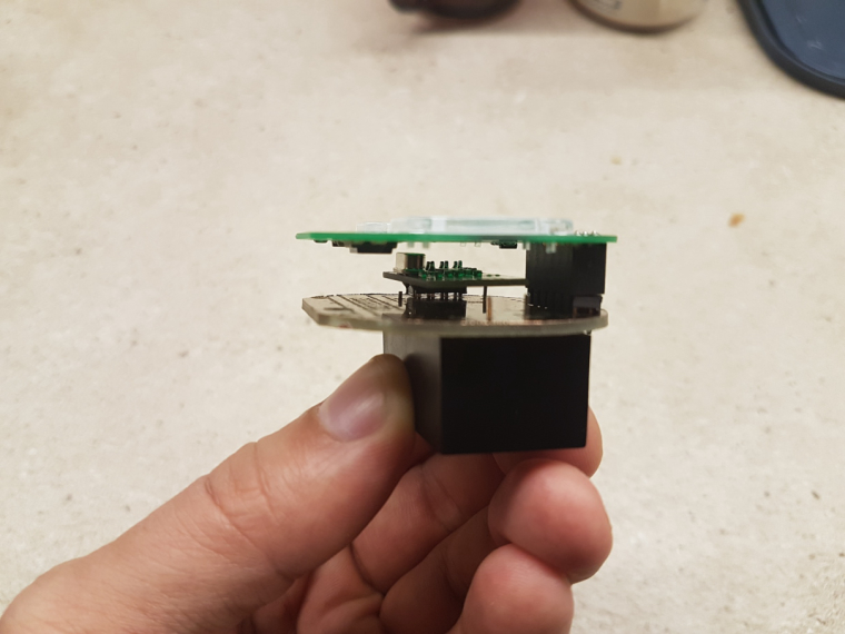
Not MySensors, but related. Power over Ethernet (802.3af compliant) addon for the raspberry pi zero. I plan to use this for high power & high reliability devices where wireless will not work.
Top one is a higher power version, bottom one just uses an off the shelf regulator.
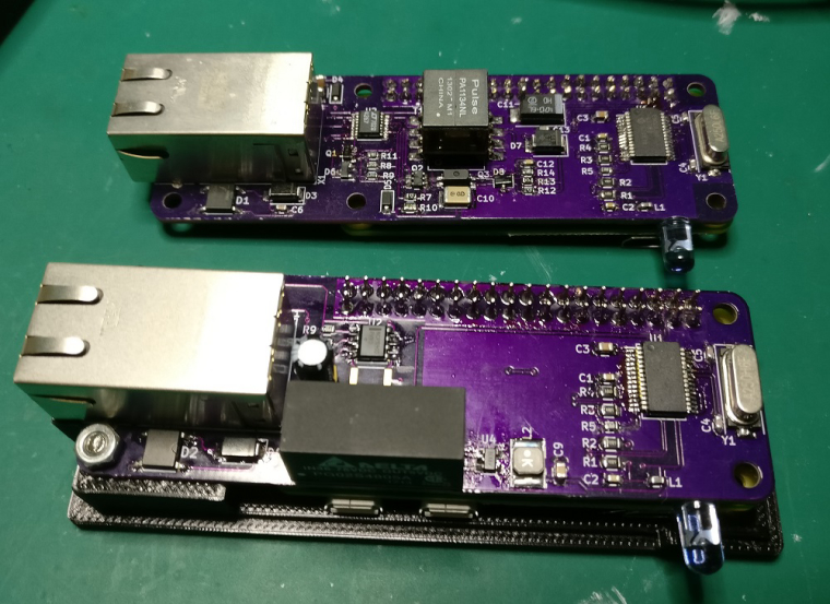
Currently these just have some IR LED's to control IR devices.
@SquareKinematics
Very useful to have. Not sure if you're aware, but you can buy PoE power adapters off the shelf. Even Amazon sells them. You select the output voltage you want with a slide switch. -
@SquareKinematics
Very useful to have. Not sure if you're aware, but you can buy PoE power adapters off the shelf. Even Amazon sells them. You select the output voltage you want with a slide switch.And so it it almost Christmas...
Jolly jolly.. wel actually no....
We have had wet feet from the central heating system serveral times now around Christmas or New Year.
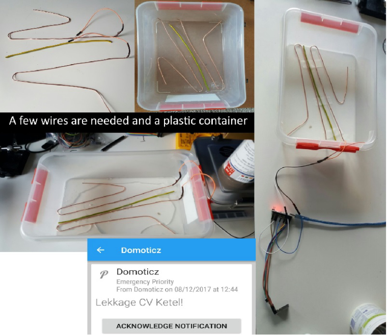
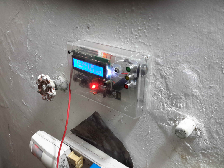
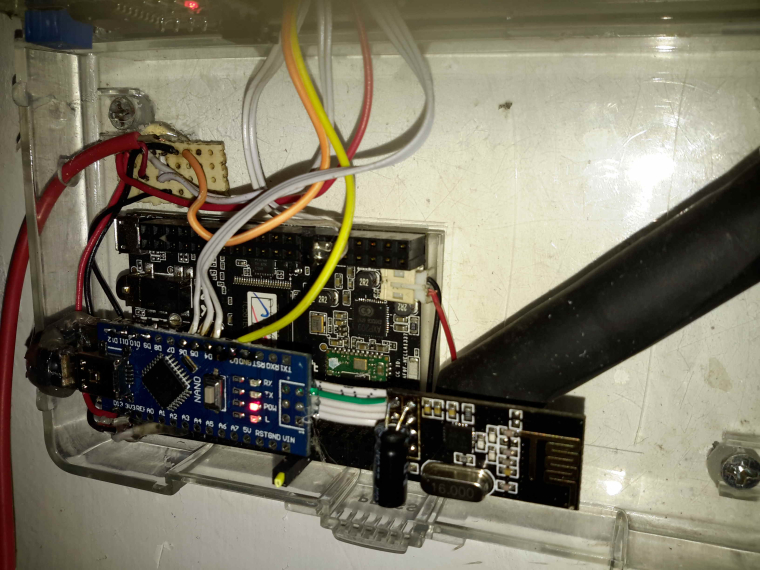
Causing a wet floor and other possible disasters. Yes I know.. A Central Heating Mechanism should not leak, you could try putting a bucket underneath... But that is not 'that home automation' smart that I was looking for.So to detect a leakage.... I came up with this some time ago.
Pretty standard, a few wires... a Mysensors Node... and Pushover to send me urgens notifications about the leakge.
 link url))
And ladies and gentlemen it actually works as you can see in the pushover sreenshot, it kicked off today.
-
And so it it almost Christmas...
Jolly jolly.. wel actually no....
We have had wet feet from the central heating system serveral times now around Christmas or New Year.
Causing a wet floor and other possible disasters. Yes I know.. A Central Heating Mechanism should not leak, you could try putting a bucket underneath... But that is not 'that home automation' smart that I was looking for.So to detect a leakage.... I came up with this some time ago.
Pretty standard, a few wires... a Mysensors Node... and Pushover to send me urgens notifications about the leakge.
link url))And ladies and gentlemen it actually works as you can see in the pushover sreenshot, it kicked off today.
@sincze You could also put some salt into your tray for added conductivity when things get wet.
-
@sincze You could also put some salt into your tray for added conductivity when things get wet.
@neverdie Great tip, this will resolve in even a quicker response during a flood right?. I already added toilet paper as cover for a smooth moist/water distribution. Lets add some salt to that and hopefully never see an error message again. But I wont bet a bitcoin on that ;-).. Happy with this cheap solution.
-
@neverdie Great tip, this will resolve in even a quicker response during a flood right?. I already added toilet paper as cover for a smooth moist/water distribution. Lets add some salt to that and hopefully never see an error message again. But I wont bet a bitcoin on that ;-).. Happy with this cheap solution.
@sincze How did you design the detection circuitry? Are you using an analog or a digital input?
Tap water should work without adding more conductivity - in my case I just designed something similar but I wanted to detect an overfill of osmosis water, which is similar to distilled. I had issues with getting it to work through a digital input, so I just built a voltage divider capable of detecting the small change in conductivity. I also added a capacitor to be sure that no false alarms would be received because of noise in the lines. It's been working perfect for days now.
-
@sincze You could also put some salt into your tray for added conductivity when things get wet.
@neverdie said in What did you build today (Pictures) ?:
@sincze You could also put some salt into your tray for added conductivity when things get wet.
Be very careful using salt,i killed an SI7021 doing something similar.
I got up one morning and found the sensor covered in white fur and it was dead:white_frowning_face: -
@sincze How did you design the detection circuitry? Are you using an analog or a digital input?
Tap water should work without adding more conductivity - in my case I just designed something similar but I wanted to detect an overfill of osmosis water, which is similar to distilled. I had issues with getting it to work through a digital input, so I just built a voltage divider capable of detecting the small change in conductivity. I also added a capacitor to be sure that no false alarms would be received because of noise in the lines. It's been working perfect for days now.
@manutremo As the water indeed is 'rock' solid here in the area I was pretty succesfull using the digital pins. A short... when there is a water connection or open... when there is no connection. No false alarms. Only legit... Each leakage costs me money to get some guy to fix it for me. But at least the floor is not ruined anymore as I had that the first 2 times.
-
@neverdie said in What did you build today (Pictures) ?:
@sincze You could also put some salt into your tray for added conductivity when things get wet.
Be very careful using salt,i killed an SI7021 doing something similar.
I got up one morning and found the sensor covered in white fur and it was dead:white_frowning_face: -
Almost Christmas, that means... Lights. In this case programmable 5v LED's that are driven by an Arduino and controlled via Mysensors & Domoticz.

While the arduino sketch has a lot of tricks (showing animations).. I still have to figure out HOW I can stop an animation from playing when I want to see the next one.. It now completes the first animation.. and then starts the one I selected. It needs to break from the function if a new message comes in. I'll have to look for some examples in the forum.
-
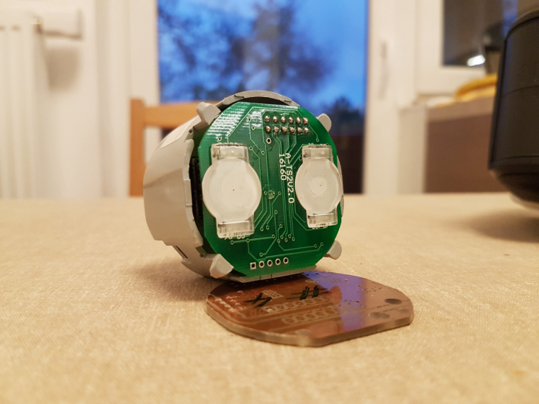
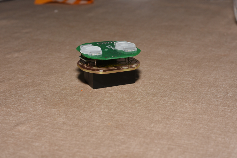
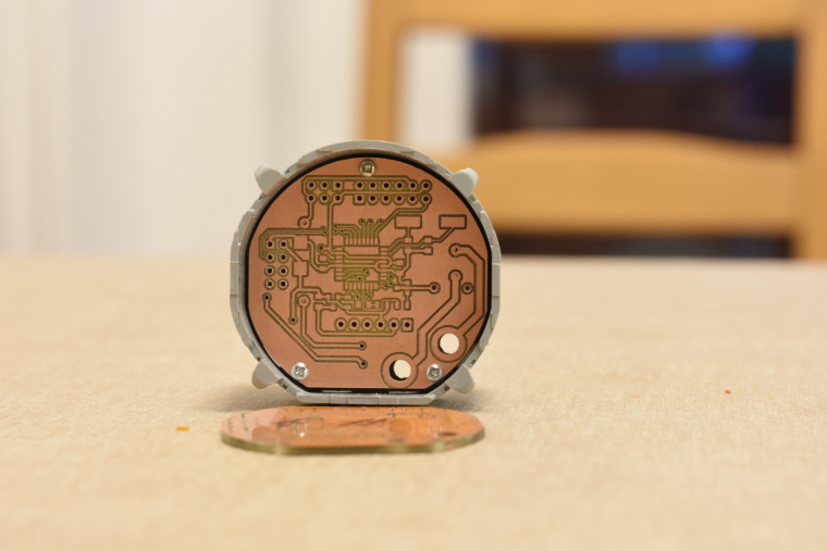
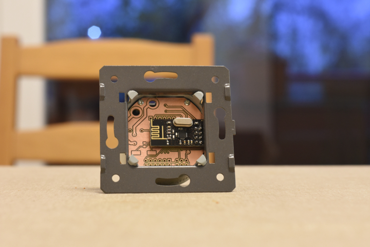
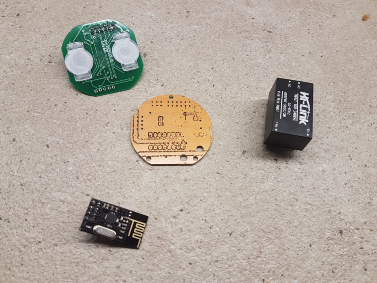
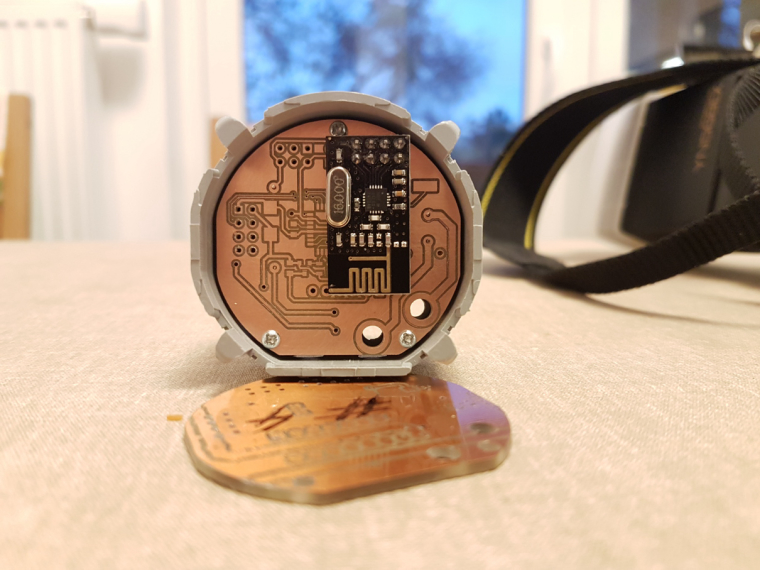
@andrew I see that You put the nrf module between two pcbs. Do You have issues with reception ? Because the boards may act as a shielding.
-
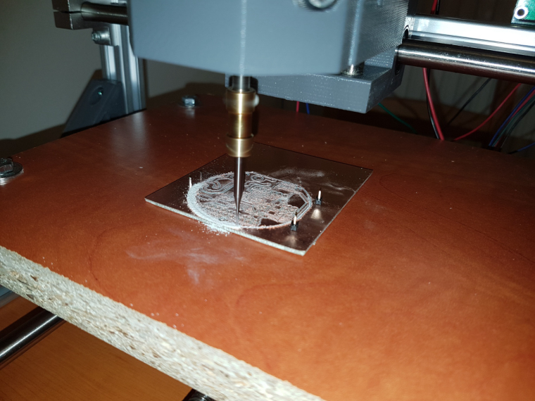
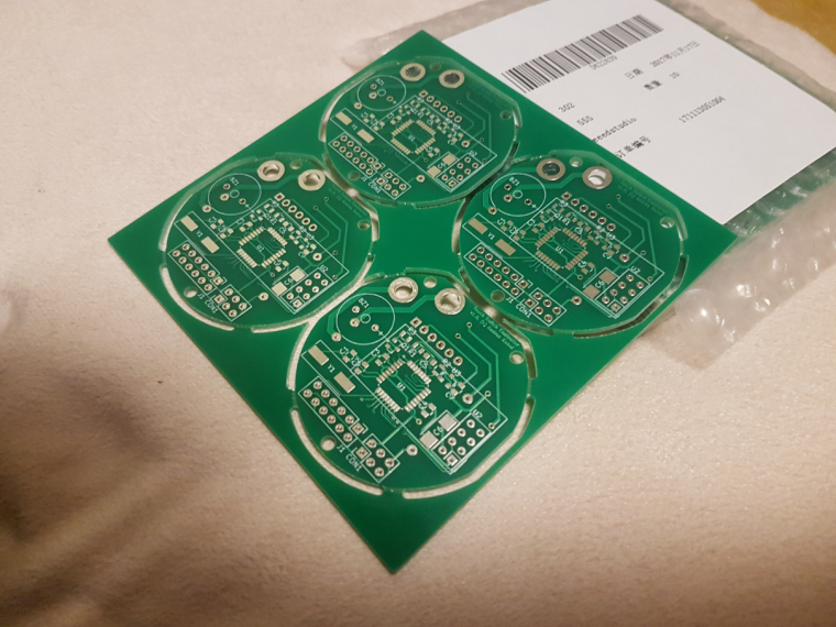
@rozpruwacz I try to avoid filled copper areas, which could act as RF blockers. as I mentioned, everything is still in progress, in-wall tests will just come. hopefully I'll have time for that in the next 2 weeks.
I know that this is not the right place to ask but I'm very curious how do you overcome the fact that in EU there's only the live with in the walls for light switches. I saw that you used a HLK-PM0xx module for testing which needs both live and null. Or maybe your "in-wall" wiring is different... Anyways congratulations for your work so far.
-
I know that this is not the right place to ask but I'm very curious how do you overcome the fact that in EU there's only the live with in the walls for light switches. I saw that you used a HLK-PM0xx module for testing which needs both live and null. Or maybe your "in-wall" wiring is different... Anyways congratulations for your work so far.
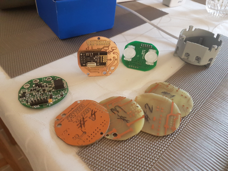
@mtiutiu well, that's the dirty hacking part :) electricians will probably not like it.
so, for first, I've a different approach to control my lamps compared to other in-wall switches and dimmers, due to the fact, that I won't switch the mains directly, with the switch. I have LED ceiling lamps which operate at 12V, but the power supplies (230V to 12V) are in the lamps' body. it could be possible to switch their mains on/off thus to turn the lamps on/off (this is what I do now with standard switches), but it is not possible to dim the lights this way.
to be able to dim the LEDs as well I'll have a lamp controller node right after the switching PSUs in each lamp. this will be controlled with the in-wall switches (and could be controlled with other nodes/gateways as well), over the air only.as all of my wall lamp switch have dual wiring (one line in, two switched line out) I planned the following setup:
one switched line will be "re-assigned" and wired to N at the lamp. this way, at the wall switch I'll have both L and N. the other switched in-wall line will still forward the L to the lamp, but it will do it directly, to continuously operate the lamp's PSU, which also powers the lamp's controller module.
the controller will be always on and it will control both the dimming (PWM on the 12V) and the switching wich basically allowing or disabling the 12V from the PSU to the LEDs.the in-wall switch will be basically just a radio remote controller this way, but operating from the mains, without any need of batteries.
I hope that my explanation wasn't too complicated :)
-
well today finally i decide to change to c.h.i.p. as a controller with domoticz an amazing device but too bad for the product that got really bad customer support, ( if you planning to buy a c.h.i.p. read the forum first to get all the problems)
this is my controller using a chip, arduino nano
planing to chage the nano to a nodemcu

 !
!