What did you build today (Pictures) ?

-
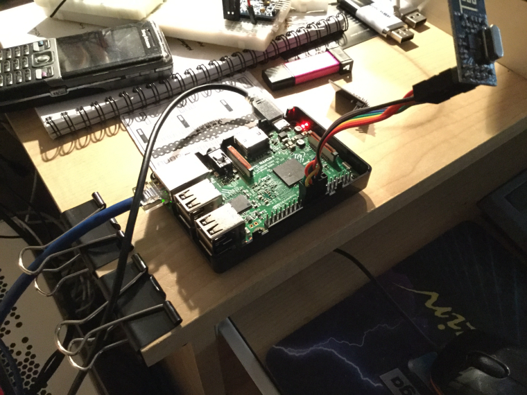
Today's build is a new raspberry pi gateway to assist troubleshooting in this thread. I use the connectors that I created earlier. Great to be able to switch radio module in the connector.
The binder clips to the left are great for keeping network and power cables in place.
-
Today's build is a new raspberry pi gateway to assist troubleshooting in this thread. I use the connectors that I created earlier. Great to be able to switch radio module in the connector.
The binder clips to the left are great for keeping network and power cables in place.
@mfalkvidd
Is your use of cables for temporary testing, or is it permanent as far as you're concerned? If the later, I'm surprised you haven't yet found a PCB solution openhardware.io that you prefer. -
@mfalkvidd
Is your use of cables for temporary testing, or is it permanent as far as you're concerned? If the later, I'm surprised you haven't yet found a PCB solution openhardware.io that you prefer. -
@NeverDie I guess it could be considered permanent by now. I have been using MySensors for more than 2 years and I've never gotten round to using any of the pcbs.
-
I'm in the mid of building a more complex sensor setup for the chicken coop, where I use dupont cables all over (actually, it's more or less the first sensor that I use them in..) I do not expect to poke around in the wires, after I have mounted it in the chicken coop at some point in time. So I recon it's going to be ok.. (And it will be hot glued into a large weatherproof junction box)
-
Rule #1 from what I've read is to keep connections as short as possible, especially when radio is involved. However, if you're not suffering from using long wires, then, well, I guess why not? If this is a prevailing belief, then maybe it does at least partially explain the remarkably low uptake of openhardware.io projects.
-
I guess the thread can evolve the way it does - but in the same time, if there are a interesting ongoing discussion all mods are more than welcome to lift that discussion out for a own thread and if so we can keep this thread as intended?
-
Last night i continued improving my Logger (mostly protecting the serial input and make sure it can handle incoming serial logic from everything from 2.5v to 5v into my 3.3v system). I finally bought myself a oscilloscope so now I have the longest list possible of things I want to improve... (EasyPCB series, Booster performance?, some relays... the list goes on).
-
Tonight I changed the mechanic trigger to a optocoupler on my doorbell node. I went with some sort of half good solution.
8v AC (Doorbell activated) -> Diode (Not a full bridge, just a support capacitor) -> Voltage divider -> optocoupler > D3. Worked out great, but might be one of the ugliest nodes I have :)Testing/Soldering/Deployment:
-
I changed the form of my integrated nRF52832-protoboard:
Previously, I was using: https://www.openhardware.io/view/472/Ebyte-nRF52832-Prototyping-Board
-
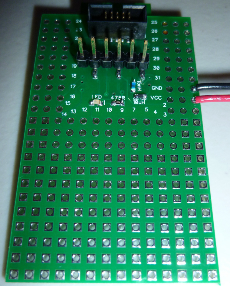
Today I made some small changes to a battery node. Once again I had copy/pasted all battery code but forgot the internalReference in setup() (since I copy from another node sketch). So I now created a dedicated file for battery code I can use to copy from... and once again I remembered I'm not a coder... But it works.
https://github.com/sundberg84/MySensors2.0.0/blob/master/BatteryMeasurer/BatteryMeasurer.ino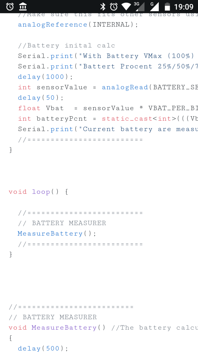
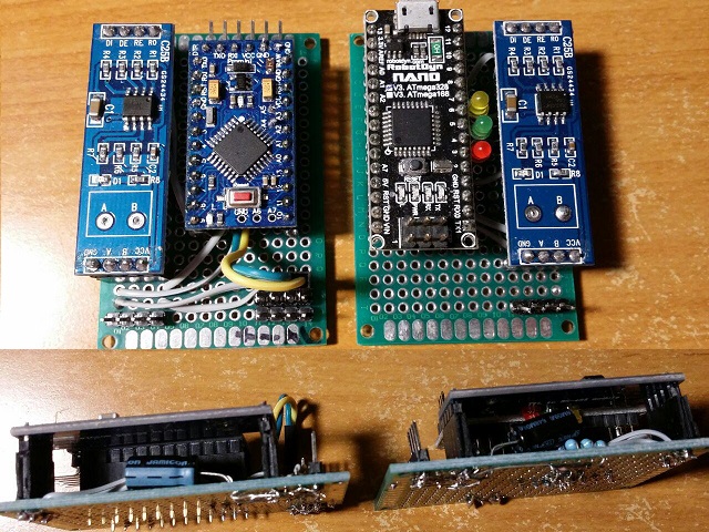
Controller: Proxmox VM - Home Assistant
MySensors GW: Arduino Uno - W5100 Ethernet, Gw Shield Nrf24l01+ 2,4Ghz
MySensors GW: Arduino Uno - Gw Shield RFM69, 433mhz
RFLink GW - Arduino Mega + RFLink Shield, 433mhz -
Today I made some small changes to a battery node. Once again I had copy/pasted all battery code but forgot the internalReference in setup() (since I copy from another node sketch). So I now created a dedicated file for battery code I can use to copy from... and once again I remembered I'm not a coder... But it works.
https://github.com/sundberg84/MySensors2.0.0/blob/master/BatteryMeasurer/BatteryMeasurer.ino@sundberg84 Not to be critical or get off topic, but it's percent, not procent
-
Simple RS485 gateway and node for two BME280 sensors:
-
Made a small tool to simplify the extraction of serial debug data from a 10-pin IDC connector and reading it from a typical 6-pin FTDI module.
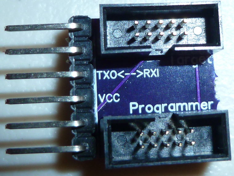
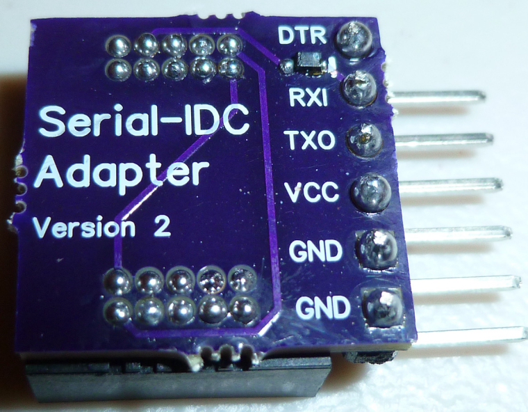
The 10-pin IDC connector is what's most commonly used for programming nRF5x modules. -
Not really MySensors-related, but I found a nice logging library for Arduino that I'm using in a project. The library was orphaned some time ago, but now has a new maintainer. I assisted with an update of the documentation and some source code cleanup.
-
I made an nRF52832 board today with 5 different colored LED's on it: red, green, yellow, orange, and blue. Mostly I think it may be useful while debugging code. All the LED's except for blue emit light all the way down to 1.8v source voltage, so it's good for battery powered operation also. The blue lights up all the way down to 2.4v, and I had to grapple with a 0403 LED to get that low of a voltage for a blue LED. In the end it was so tiny that I couldn't see the polarity of it, so I hit on the idea of running a blink program and seeing whether it would light up just before I soldered it in place. That worked. :)
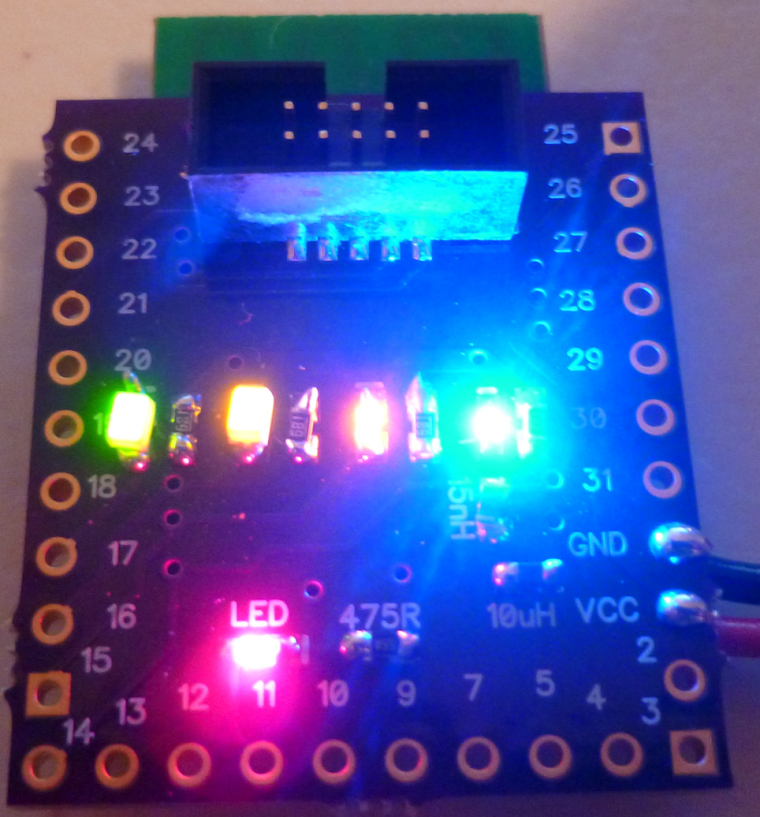
Also, this board channels its serial output over the 10-pin IDC connector, so I used the tool I posted yesterday to read it. Works great, and now I don't have a six pin FTDI connector cluttering up the PCB. :)
-
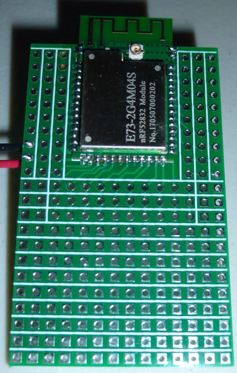
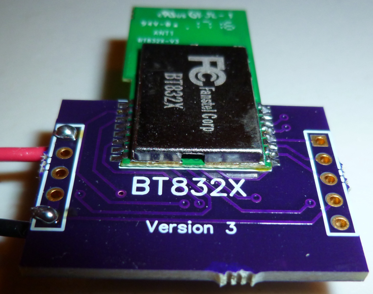
Today my boards for the BT832X (that's an nRF52832 with both PA and LNA) arrived from OSH PARK, so I put one together to try it out:
![0_1508764679200_2016-02-09-21h05m49-[DSC_0001].jpg](/assets/uploads/files/1508764680235-2016-02-09-21h05m49-dsc_0001-resized.jpeg)