What did you build today (Pictures) ?

-
-
-
Added a buzzer to my nRF51822 coincell device to make a locator beacon. Attach the device to an object you tend to lose and it will make sounds when you activate it, allowing you to find it.
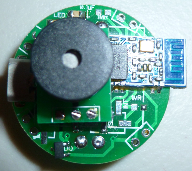
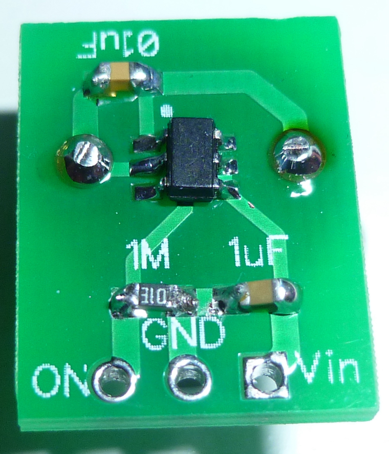
The buzzer is driven by a load switch, so that none of the nRF51822 pins are overloaded:
-
Added a buzzer to my nRF51822 coincell device to make a locator beacon. Attach the device to an object you tend to lose and it will make sounds when you activate it, allowing you to find it.
The buzzer is driven by a load switch, so that none of the nRF51822 pins are overloaded:
-
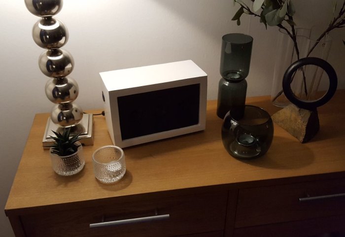
Finally, the last day of my holiday I managed to upload the Mysensors Sketch into the NodeMCU to control my 900 LEDS. It will also read the lux intensity in the livingroom. So if it is dark the lights will switch on.
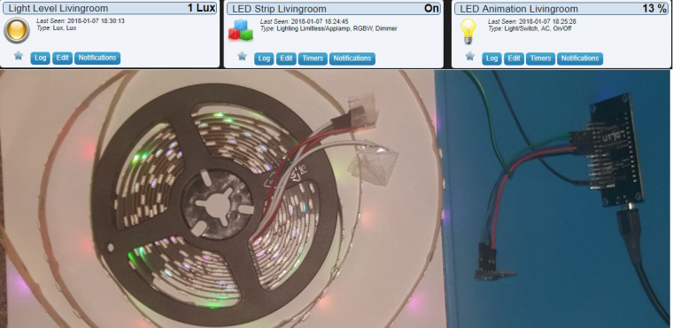
All is based on @Yveaux Mysensors ESP Gateway port. On a rainy saterday last year @Yveaux and I found out we did not have to modify anything on the voltag level for driving the LEDS. ;)
The sketch includes all the Doll_House animations (around 55) that can be skipped through using an old 433mhz remote (or via interface directly ofcourse) Next stop... Installing 15 meters of LED in the livingroom. pffff ;-)
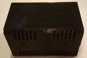
And putting everything inside this little box @Yveaux printed for me.
-
Hi,
today I've almost finished a speaker build :) (it'll be a gift for family)
First, I would like to thx Paul Carmody who created the original design of these speakers : Overnight Sensation :clap: :+1:
https://sites.google.com/site/undefinition/diy-overnightsensationsI have just changed size and format (of course I kept the internal air volume which is very important)
-
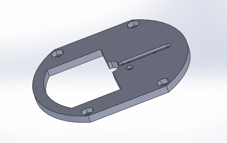
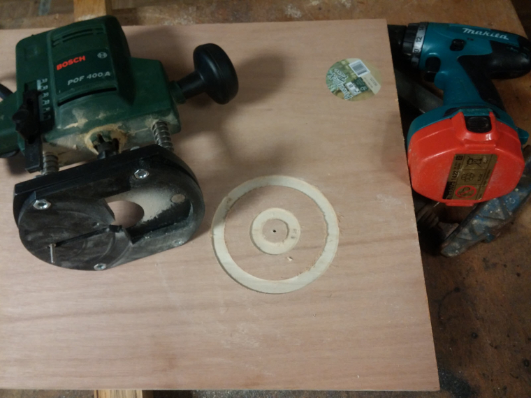
I designed&printed a simple circle jig for my router.
-
So speaker drivers can be flush on front plate
-
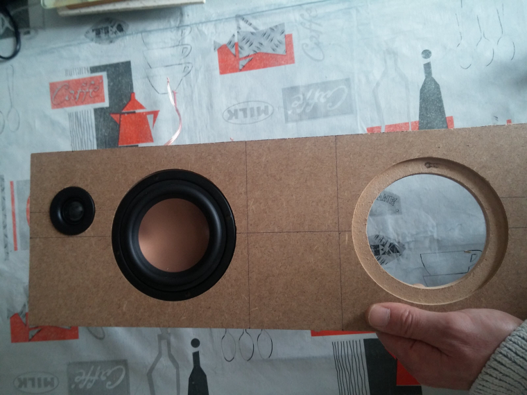
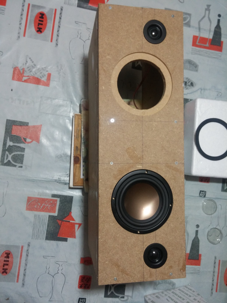
Assembled the box
-
Crossover, port tube, foam
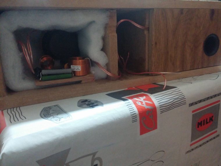
with a special place to fit some electronics like
- rpi (for Volumio/LMS client, or a voice assistant)
- cheap dac & 2x50w amp from aliexpress
- Now vinyling. I need to change these ugly black screws too.
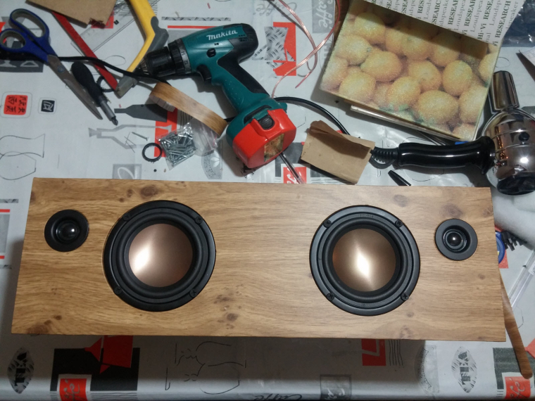
Of course, I'm too excited (and not very patient ), so I've tested how they sound... Loud! Crystal sound with very nice boomboom :muscle:
Not finished, but in good way :)
-
-
Hi,
today I've almost finished a speaker build :) (it'll be a gift for family)
First, I would like to thx Paul Carmody who created the original design of these speakers : Overnight Sensation :clap: :+1:
https://sites.google.com/site/undefinition/diy-overnightsensationsI have just changed size and format (of course I kept the internal air volume which is very important)
-
I designed&printed a simple circle jig for my router.
-
So speaker drivers can be flush on front plate
-
Assembled the box
-
Crossover, port tube, foam
with a special place to fit some electronics like
- rpi (for Volumio/LMS client, or a voice assistant)
- cheap dac & 2x50w amp from aliexpress
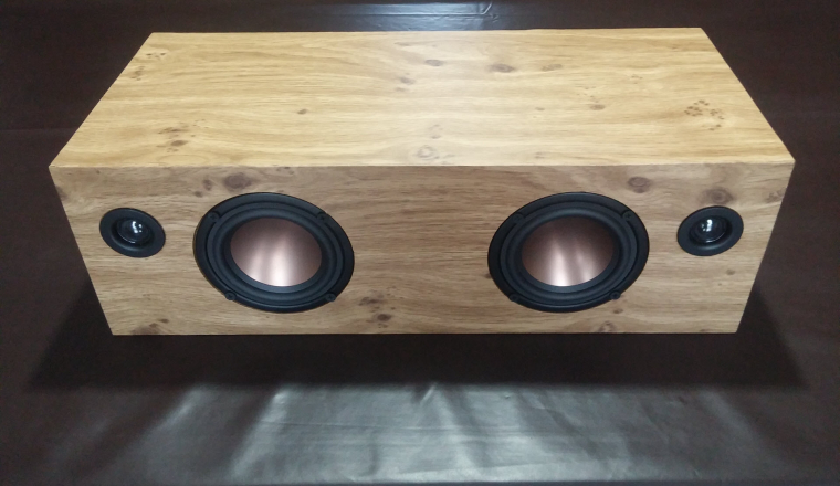
- Now vinyling. I need to change these ugly black screws too.
Of course, I'm too excited (and not very patient ), so I've tested how they sound... Loud! Crystal sound with very nice boomboom :muscle:
Not finished, but in good way :)
@scalz I have to guess this is a centre speaker?
Some tidy inductors there on the crossover...
How times have changed, now you can PRINT a router jig, used to make them with a piece of plywood for circles smaller that the router radius... Centre was drilled and fitted with threaded rod so you could cut back the front of the baffle but also chamfer the back face of the speaker baffle before cutting out the opening...
Tidy enough, great when they get fired up.... -
-
Today I (finally) finished a full working version of that old Livolo 3 buttons switch. I removed the RGB led on the central button as it's not visible, but the basic switch functionality with buttons/relays and blue/red status leds runs fine.
It's running with MYSBootloader, it's really convenient to update without having to switch of the fuse and unmount everything.
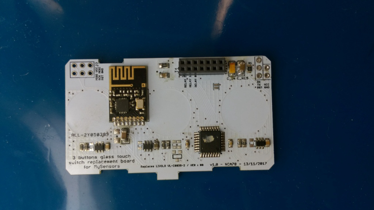
A (quick) video, touch sensibility is perfect now, I'm really happy with it !
https://www.youtube.com/watch?v=G6yEdSyoMYw -
Hi,
today I've almost finished a speaker build :) (it'll be a gift for family)
First, I would like to thx Paul Carmody who created the original design of these speakers : Overnight Sensation :clap: :+1:
https://sites.google.com/site/undefinition/diy-overnightsensationsI have just changed size and format (of course I kept the internal air volume which is very important)
-
I designed&printed a simple circle jig for my router.
-
So speaker drivers can be flush on front plate
-
Assembled the box
-
Crossover, port tube, foam
with a special place to fit some electronics like
- rpi (for Volumio/LMS client, or a voice assistant)
- cheap dac & 2x50w amp from aliexpress
- Now vinyling. I need to change these ugly black screws too.
Of course, I'm too excited (and not very patient ), so I've tested how they sound... Loud! Crystal sound with very nice boomboom :muscle:
Not finished, but in good way :)
-
-
@scalz I have to guess this is a centre speaker?
Some tidy inductors there on the crossover...
How times have changed, now you can PRINT a router jig, used to make them with a piece of plywood for circles smaller that the router radius... Centre was drilled and fitted with threaded rod so you could cut back the front of the baffle but also chamfer the back face of the speaker baffle before cutting out the opening...
Tidy enough, great when they get fired up....@zboblamont
well actually it's setup as a standalone stereo speaker. I asked my brother (it's a gift for him) if he would prefer separated speakers (better for stereo). But he prefers like this, standalone with no wires, and his room won't be wide so it should be ok.
Yes, i know for the jigs in plywood, but i have a 3d printer, caliper; drawing, print and voilà :)
I like using cad software for checking assemblies in 3d etc, very handy, and it's more precise than my brain :).@fredswed yeah, it sounds very nice. when you hear it, then you know you made the good choice. Better than buying any of these 60 to >200$ smart speakers. I compared them with some others hifi speakers (jbl..) for fun, and still very impressive. Some of my friends are jealous. They want one, or more. Same for my others bro. They sound pretty loud imho, and would like to try a pair like that for fun
I ordered most of the parts at loudspeakerfreaks or audiohobby. if you live in USA, then it's better to give a try to parts express I think.I finished the vinyling yesterday (my bro didn't want I roundish the corner). I now just need to add a rpi inside and connectors etc on back, not bad :)
-
@zboblamont
well actually it's setup as a standalone stereo speaker. I asked my brother (it's a gift for him) if he would prefer separated speakers (better for stereo). But he prefers like this, standalone with no wires, and his room won't be wide so it should be ok.
Yes, i know for the jigs in plywood, but i have a 3d printer, caliper; drawing, print and voilà :)
I like using cad software for checking assemblies in 3d etc, very handy, and it's more precise than my brain :).@fredswed yeah, it sounds very nice. when you hear it, then you know you made the good choice. Better than buying any of these 60 to >200$ smart speakers. I compared them with some others hifi speakers (jbl..) for fun, and still very impressive. Some of my friends are jealous. They want one, or more. Same for my others bro. They sound pretty loud imho, and would like to try a pair like that for fun
I ordered most of the parts at loudspeakerfreaks or audiohobby. if you live in USA, then it's better to give a try to parts express I think.I finished the vinyling yesterday (my bro didn't want I roundish the corner). I now just need to add a rpi inside and connectors etc on back, not bad :)
@scalz - im using volumio (finished image for RPI) and happy with this. Just a tip...
Controller: Proxmox VM - Home Assistant
MySensors GW: Arduino Uno - W5100 Ethernet, Gw Shield Nrf24l01+ 2,4Ghz
MySensors GW: Arduino Uno - Gw Shield RFM69, 433mhz
RFLink GW - Arduino Mega + RFLink Shield, 433mhz -
@scalz - im using volumio (finished image for RPI) and happy with this. Just a tip...
@sundberg84 said in What did you build today (Pictures) ?:
@scalz - im using volumio (finished image for RPI) and happy with this. Just a tip...
same here with a few additional plugins ;) Agreed, volumio is sexy sw.
your speaker looks nice :+1:
I read and learnt a lot how to make diy speakers. It was very interesting learning curve, lot of parameters I didn't know before (and one of the most important rule is : tune your enclosure regarding speaker drivers specs, not the oppposite (there are software for calculating everything) Now I understand better the curves etc and where commercial stuff cheats. pretty cool
-
@sundberg84 said in What did you build today (Pictures) ?:
@scalz - im using volumio (finished image for RPI) and happy with this. Just a tip...
same here with a few additional plugins ;) Agreed, volumio is sexy sw.
your speaker looks nice :+1:
I read and learnt a lot how to make diy speakers. It was very interesting learning curve, lot of parameters I didn't know before (and one of the most important rule is : tune your enclosure regarding speaker drivers specs, not the oppposite (there are software for calculating everything) Now I understand better the curves etc and where commercial stuff cheats. pretty cool
@scalz - this was my first project and I agree with you (because I didnt calculate much before). If you are looking for the best sound its incredible important... for me and this build I wanted a small enclosure in the kitchen but the sound is pretty impressive for such a small thing so Im happy even though I know it could have sounded better.
-
@zboblamont
well actually it's setup as a standalone stereo speaker. I asked my brother (it's a gift for him) if he would prefer separated speakers (better for stereo). But he prefers like this, standalone with no wires, and his room won't be wide so it should be ok.
Yes, i know for the jigs in plywood, but i have a 3d printer, caliper; drawing, print and voilà :)
I like using cad software for checking assemblies in 3d etc, very handy, and it's more precise than my brain :).@fredswed yeah, it sounds very nice. when you hear it, then you know you made the good choice. Better than buying any of these 60 to >200$ smart speakers. I compared them with some others hifi speakers (jbl..) for fun, and still very impressive. Some of my friends are jealous. They want one, or more. Same for my others bro. They sound pretty loud imho, and would like to try a pair like that for fun
I ordered most of the parts at loudspeakerfreaks or audiohobby. if you live in USA, then it's better to give a try to parts express I think.I finished the vinyling yesterday (my bro didn't want I roundish the corner). I now just need to add a rpi inside and connectors etc on back, not bad :)
@scalz Whatever, so long as your brother enjoys what he asked for, job done.
Do I interpret your comment on "roundish the corner" as rounding over the front baffle edges? Sonically it can make a difference for imaging, but with drives this close I doubt it would be noticeable anyway, and would be a pain to vinyl let alone veneer....Almost 50 years I've been building speakers as a hobby....
I'll finish them one day ;) -
Maybe you speaker geniuses can figure out the optimal enclosure for this tiny buzzer? https://www.aliexpress.com/item/2731HZ-3x4-5x1-9mm-Super-small-miniature-AAC-electromagnetic-DET402-G-1-SMD-Passive-buzzer-3/32839766133.html?spm=2114.search0204.3.177.AclxtY&ws_ab_test=searchweb0_0&aff_platform=aaf&cpt=1515527880409&sk=e2Vzr3v&aff_trace_key=7078a47c52334a31ac1f2c6cfa07a508-1515527880409-05187-e2Vzr3v&terminal_id=892660b32ab149c8a0ca840218581bea
I find that if I cup my hand over it, it (somewhat counter-intuitively) gets a lot louder, so I guess the same principles are involved?
It would be neat to have a very tiny buzzer like this available for use in projects, but I guess the enclosure design needs to be considered as well so as to get more volume out of it.
-
Maybe you speaker geniuses can figure out the optimal enclosure for this tiny buzzer? https://www.aliexpress.com/item/2731HZ-3x4-5x1-9mm-Super-small-miniature-AAC-electromagnetic-DET402-G-1-SMD-Passive-buzzer-3/32839766133.html?spm=2114.search0204.3.177.AclxtY&ws_ab_test=searchweb0_0&aff_platform=aaf&cpt=1515527880409&sk=e2Vzr3v&aff_trace_key=7078a47c52334a31ac1f2c6cfa07a508-1515527880409-05187-e2Vzr3v&terminal_id=892660b32ab149c8a0ca840218581bea
I find that if I cup my hand over it, it (somewhat counter-intuitively) gets a lot louder, so I guess the same principles are involved?
It would be neat to have a very tiny buzzer like this available for use in projects, but I guess the enclosure design needs to be considered as well so as to get more volume out of it.
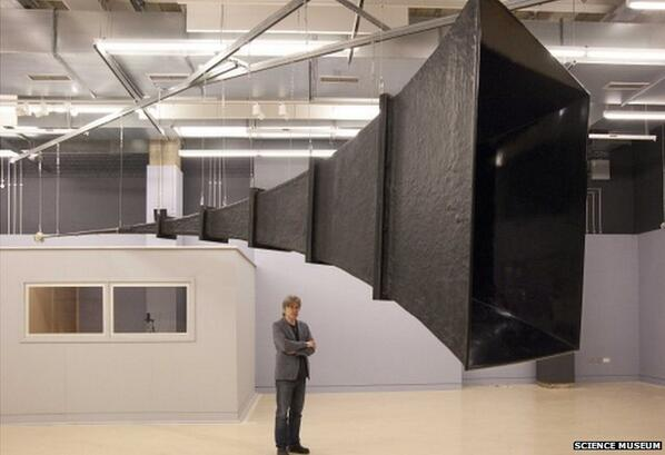
@neverdie said in What did you build today (Pictures) ?:
Maybe you speaker geniuses can figure out the optimal enclosure for this tiny buzzer?
I'll play my "I am not a speaker designer, but..." card! Here is some basic info. :grin:
Jokes aside, a piece of PVC tubing might work. You need something to make the buzzer move the air more efficiently. I'd put a 1/4 wavelength long PVC piping over the buzzer as
a first try. (Any odd multiple of 1/4 wavelength should provide some resonance.)In a more elaborate design, you could try a simple horn. Aim for a size where both the length of the horn and its circumference at the end is ca 1 wavelength.
-
Maybe you speaker geniuses can figure out the optimal enclosure for this tiny buzzer? https://www.aliexpress.com/item/2731HZ-3x4-5x1-9mm-Super-small-miniature-AAC-electromagnetic-DET402-G-1-SMD-Passive-buzzer-3/32839766133.html?spm=2114.search0204.3.177.AclxtY&ws_ab_test=searchweb0_0&aff_platform=aaf&cpt=1515527880409&sk=e2Vzr3v&aff_trace_key=7078a47c52334a31ac1f2c6cfa07a508-1515527880409-05187-e2Vzr3v&terminal_id=892660b32ab149c8a0ca840218581bea
I find that if I cup my hand over it, it (somewhat counter-intuitively) gets a lot louder, so I guess the same principles are involved?
It would be neat to have a very tiny buzzer like this available for use in projects, but I guess the enclosure design needs to be considered as well so as to get more volume out of it.
@neverdie Would this work ?
-
All I know is that there's no point to using a super small buzzer if it requires something big to make it work loud enough.
Maybe this is why the buzzer that I'm currently using instead has such a comparatively large form factor.... i.e. maybe there's just no getting around it.