What did you build today (Pictures) ?

-
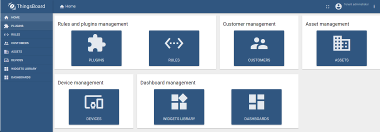
Today I'm trying out Thingsboard, which sort of is a controller, but on steroids.
So far, it seems quite capable, but I have a lot of learning to do. My first step was to integrate it with Sigfox, which seems to work.
-
Hey @mfalkvidd were you able to get mysensors nodes to send data to thingsboard? If so, I'm interested to know how you did that. Wondering if thingsboard can be configured as a controller for mysensors. Thanks!
-
@mfalkvidd no problem, thanks
-
So today I created a simple python script to bridge serial gateway with mqtt bus on my RPI:
https://github.com/mczerski/MySensorsSerial2MQTTThis is because I already use spi for nrf24 module mounted on a custom pcb so there is no room for another spi device.
-
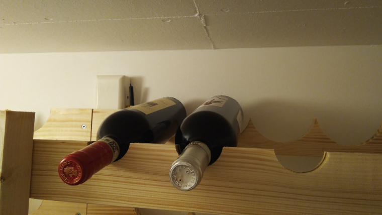
I'm building a wine rack for my wife in a celler room (currently 14 dgr with 4 dgr outside). I mowed my beer cooler temp node (rfm radio) to measure how much the temp changed over the day. I wrote a script in Lua/Domoticz that each time it changes 1dgr it should notify me. Apparently is a stable temp the most important to store wine.
All ideas how I can automate the shit out of this wine-room are appreciated.
-
LCD display with temp/hum (both on the floor and celling) (Red needs apparently cooler than white wine... Or the opposite).
-
I'm thinking about to try a passive cooler. A burried hose/pipe in a loop with a 12v fan/pump and temp. My idea is that if I rotate the 14dgr air in a say 20m pipe under ground it should cool the air some . This needs to be automated to keep the temp stable.
-
light. Some sort of led strips.
Controller: Proxmox VM - Home Assistant
MySensors GW: Arduino Uno - W5100 Ethernet, Gw Shield Nrf24l01+ 2,4Ghz
MySensors GW: Arduino Uno - Gw Shield RFM69, 433mhz
RFLink GW - Arduino Mega + RFLink Shield, 433mhz -
-
I'm building a wine rack for my wife in a celler room (currently 14 dgr with 4 dgr outside). I mowed my beer cooler temp node (rfm radio) to measure how much the temp changed over the day. I wrote a script in Lua/Domoticz that each time it changes 1dgr it should notify me. Apparently is a stable temp the most important to store wine.
All ideas how I can automate the shit out of this wine-room are appreciated.
-
LCD display with temp/hum (both on the floor and celling) (Red needs apparently cooler than white wine... Or the opposite).
-
I'm thinking about to try a passive cooler. A burried hose/pipe in a loop with a 12v fan/pump and temp. My idea is that if I rotate the 14dgr air in a say 20m pipe under ground it should cool the air some . This needs to be automated to keep the temp stable.
-
light. Some sort of led strips.
@sundberg84 Yeah, this brings back memories, particularly of quite a few hangovers.
I used 3 and four wide fireclay pipes for bottle storage, they were used for ducts back in the day before plastics took over, cable went optic fibre. I noticed recently here they are back in stock in stores as....yep...wine storage racks.... but wacko pricing relatively...
The beauty of the fireclay was it's slow temperature and humidity change, and this formed the bulk of the thermal mass in the cellar I made below the floor.
I used a 150mm glazed ceramic drainage pipe dug in under the garden as a loop (rope caulked joints - anybody remember them), from memory down about 1.5m, both avoiding frosts and baking sun, don't think the temperature varied over a degree all year round, the ground acting as a massive heatsink which maintained a constant temperature all year round.
Only when the hatch was opened did the temperature jump, a small fan kicked in when the hatch was closed and ran for 30 minutes, a second contact switched on the lights and shut them off, long before LEDs were so prevalent, old reliable (until you were depending on them) incandescent bulbs.
That was it really.
Biggest problem I found was humidity in the early days, probably the fresh construction... -
-
My wine rack is at the store. ;)
-
I'm building a wine rack for my wife in a celler room (currently 14 dgr with 4 dgr outside). I mowed my beer cooler temp node (rfm radio) to measure how much the temp changed over the day. I wrote a script in Lua/Domoticz that each time it changes 1dgr it should notify me. Apparently is a stable temp the most important to store wine.
All ideas how I can automate the shit out of this wine-room are appreciated.
-
LCD display with temp/hum (both on the floor and celling) (Red needs apparently cooler than white wine... Or the opposite).
-
I'm thinking about to try a passive cooler. A burried hose/pipe in a loop with a 12v fan/pump and temp. My idea is that if I rotate the 14dgr air in a say 20m pipe under ground it should cool the air some . This needs to be automated to keep the temp stable.
-
light. Some sort of led strips.
Why not just collect the temperatures over time, in f.ex. influxdb, and then use grafana to analyze data? (Instead of pushing messages to your phone whenever the temperature changes..)
-
-
Why not just collect the temperatures over time, in f.ex. influxdb, and then use grafana to analyze data? (Instead of pushing messages to your phone whenever the temperature changes..)
@tbowmo well I have Domoticz to collect data. Maybe your alternative is much better but I can't change from Domoticz without redo everything. The push is just to get a heads-up how often or changes but I can go into Domoticz and follow 15 min updates as well on a daily, weekly and monthly graph .
-
Why not just collect the temperatures over time, in f.ex. influxdb, and then use grafana to analyze data? (Instead of pushing messages to your phone whenever the temperature changes..)
-
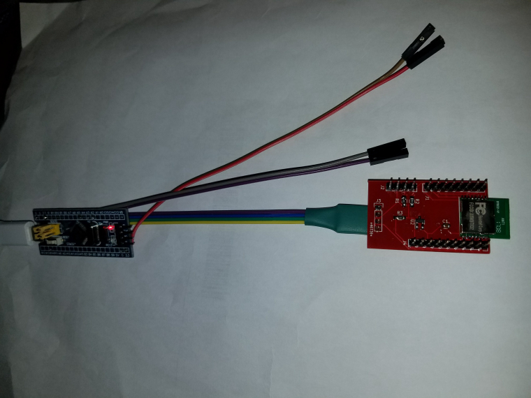
I finally got a BT832 (NRF52832 from Fanstel) to talk to my NRF24 gateway. I got the NFR5s a while ago. Made a quick breakout board (quick to design, but slow delivery). In the mean time, I configured a STM32 "Blue Pill" as a Blackmagic Probe to program it. I had to get the latest Sandeep Mistry NRF5 files from github in order for it to support the blackmagic probe, but . . . it worked : ) So far I have just run the MockMySensors and it shows up on Domoticz.
-
@tbowmo well I have Domoticz to collect data. Maybe your alternative is much better but I can't change from Domoticz without redo everything. The push is just to get a heads-up how often or changes but I can go into Domoticz and follow 15 min updates as well on a daily, weekly and monthly graph .
-
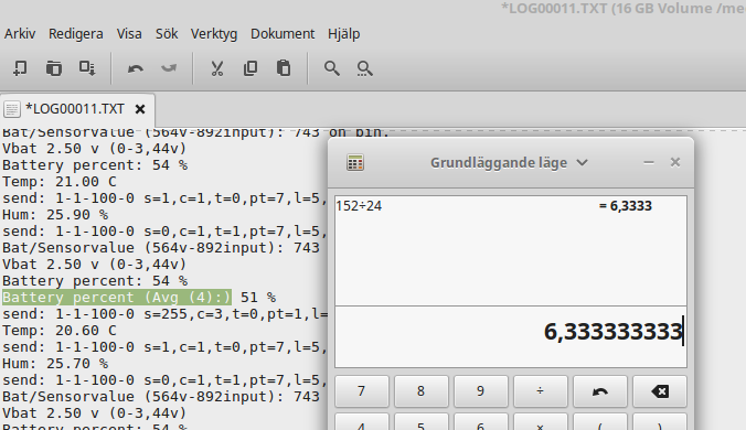
6.3 days or 152hours just inst good enough - this is what my logger managed to do with 2xAA debugging a temp/hum node sending every 15min. Its below 50% to target (14 days) but this included the leds was on all the time... how much can a 2x leds do :neutral_face: ?? Next experiemtn...
-
So for a few days now I have been working on my idea for a homebrew CNC machine made from mostly salvaged parts. This weekend I made some good progress getting the Y axis drive assembly mostly done. I have not tested anything yet, but I hope to in the next few days. Anyways, here is what I have...
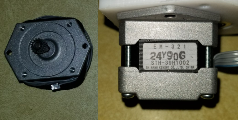
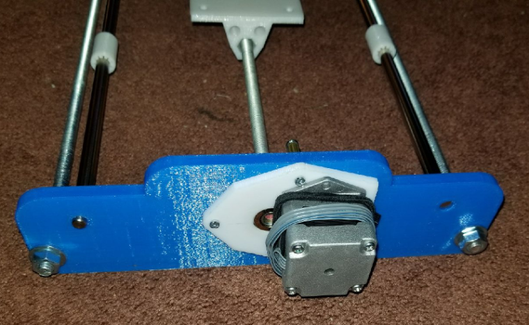
The stepper motor is one salvaged from an old dot matrix printer. The gear on it was press fit on the shaft with no real way to get it off, so I opted to make a geared drive assembly. I realize that this will slow the Y axis down, but it should also give it a bit more precision. Below is the stepper motor.
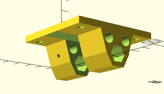
For mounting it, I designed this adapter plate which carries a steel roller bearing for the screw shaft.
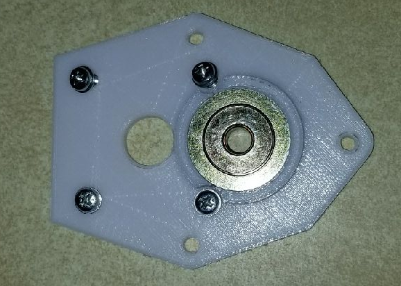
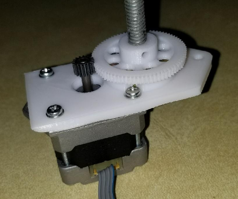
This is an early mounting plate design before I added the upper and lower mounting tabs. This shows the gear with the shaft attached. The gear was made using an OpenSCAD gear library.
Yesterday I designed the bracket that attaches to and drives the Y axis platter/build plate (Sorry, forgot to take a decent pic of that part).
Today I was able to finish the front and rear frame braces and got parts rough fitted together. the 2 rails with the small white linear bearings are some rods that were salvaged from a couple old scanners. These were used as the rail for the scanner head. I have pics of the full assembly as well as the motor assembly mounted on the rear brace.
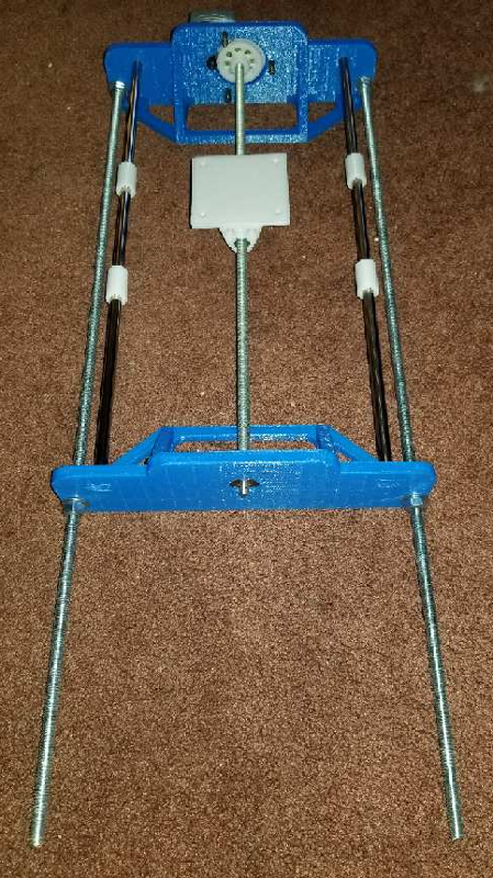
I can't say how well the design will work, if at all, but it has been a fun journey so far trying.
-
So for a few days now I have been working on my idea for a homebrew CNC machine made from mostly salvaged parts. This weekend I made some good progress getting the Y axis drive assembly mostly done. I have not tested anything yet, but I hope to in the next few days. Anyways, here is what I have...
The stepper motor is one salvaged from an old dot matrix printer. The gear on it was press fit on the shaft with no real way to get it off, so I opted to make a geared drive assembly. I realize that this will slow the Y axis down, but it should also give it a bit more precision. Below is the stepper motor.
For mounting it, I designed this adapter plate which carries a steel roller bearing for the screw shaft.
This is an early mounting plate design before I added the upper and lower mounting tabs. This shows the gear with the shaft attached. The gear was made using an OpenSCAD gear library.
Yesterday I designed the bracket that attaches to and drives the Y axis platter/build plate (Sorry, forgot to take a decent pic of that part).
Today I was able to finish the front and rear frame braces and got parts rough fitted together. the 2 rails with the small white linear bearings are some rods that were salvaged from a couple old scanners. These were used as the rail for the scanner head. I have pics of the full assembly as well as the motor assembly mounted on the rear brace.
I can't say how well the design will work, if at all, but it has been a fun journey so far trying.
@dbemowsk
Well it looks as if your 3D-printer works fine :grinning:What I would be slightly worried about is if with the given size of the rods the stiffness of the structure would be enough.
Hope to see more from this project in the near future.
Good luck! -
@dbemowsk
Well it looks as if your 3D-printer works fine :grinning:What I would be slightly worried about is if with the given size of the rods the stiffness of the structure would be enough.
Hope to see more from this project in the near future.
Good luck!@boozz I will be curious to see if I can get enough precision to do PCBs. I have yet to buy a GRBL board to control it. For now I am going to use the UNO that I have for testing just to do test runs of the servos until I get one. This is the one I have been looking at:
https://www.ebay.com/itm/Arduino-CNC-Shield-Kit-UNO-Board-4x-DRV8825-Drivers-Package-Deal-FREE-USA-SHIP/292174947187?hash=item4406fbe373:g:A0sAAOSwJThZpeKr
I will also have to figure out the gear ratios of the motor assemblies once I am done because I am sure I will need them to calibrate the GRBL setup. I know on this part of it I have about a 4.8:1 ratio from the motor to the large gear, but I'll have to figure out steps per cm or steps per mm or something. If anyone knows a good way of figuring this out I am all ears.Thanks for the upvotes.
Vera Plus running UI7 with MySensors, Sonoffs and 1-Wire devices
Visit my website for more Bits, Bytes and Ramblings from me: http://dan.bemowski.info/ -
@boozz I will be curious to see if I can get enough precision to do PCBs. I have yet to buy a GRBL board to control it. For now I am going to use the UNO that I have for testing just to do test runs of the servos until I get one. This is the one I have been looking at:
https://www.ebay.com/itm/Arduino-CNC-Shield-Kit-UNO-Board-4x-DRV8825-Drivers-Package-Deal-FREE-USA-SHIP/292174947187?hash=item4406fbe373:g:A0sAAOSwJThZpeKr
I will also have to figure out the gear ratios of the motor assemblies once I am done because I am sure I will need them to calibrate the GRBL setup. I know on this part of it I have about a 4.8:1 ratio from the motor to the large gear, but I'll have to figure out steps per cm or steps per mm or something. If anyone knows a good way of figuring this out I am all ears.Thanks for the upvotes.
-
@boozz I will be curious to see if I can get enough precision to do PCBs. I have yet to buy a GRBL board to control it. For now I am going to use the UNO that I have for testing just to do test runs of the servos until I get one. This is the one I have been looking at:
https://www.ebay.com/itm/Arduino-CNC-Shield-Kit-UNO-Board-4x-DRV8825-Drivers-Package-Deal-FREE-USA-SHIP/292174947187?hash=item4406fbe373:g:A0sAAOSwJThZpeKr
I will also have to figure out the gear ratios of the motor assemblies once I am done because I am sure I will need them to calibrate the GRBL setup. I know on this part of it I have about a 4.8:1 ratio from the motor to the large gear, but I'll have to figure out steps per cm or steps per mm or something. If anyone knows a good way of figuring this out I am all ears.Thanks for the upvotes.
@dbemowsk said in What did you build today (Pictures) ?:
If anyone knows a good way of figuring this out I am all ears.
It would expect making a large movement using a defined number of steps, and measuring the actual distance moved with a caliper will give you a rather accurate steps/mm.
However, I hope this ratio is constant over the whole range, given the 3d printed gears and expected backlash...http://yveaux.blogspot.nl