What did you build today (Pictures) ?

-
@sundberg84 thanks for the offer, I can wait for the final, no worries. Do you have a list of the new components added on the back?
@mickecarlsson - sure.
Signing: atsha204a (sot-32-3), R4: 1k-100k resistor (0805), C5 0,1uF capacitor (0805)
Flash: R7: 56k-100k resistor (0805), C7; 0,1uF capacitor (0805), U5: AT25DF512C or equivalent SPI Serial Flash Memory (8-lead SOIC). I bought this from Germany (but not tested) -
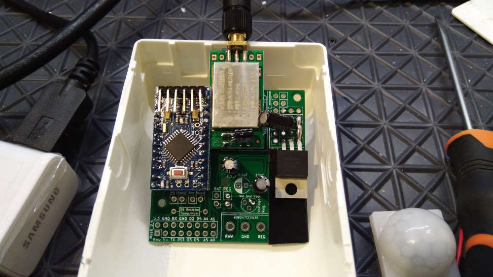
Yesterday I tested the new EasyPCB with RFM radio and hardware signing. Worked out as expected and I'm going to release all files soon.
I haven't tested the flash part yet but I'm hoping this is working as well.
This picture will be a part of a new video with me building my new RFM69 serial gateway using signing.
Anyone they can guess which issue I had when I took the photo?
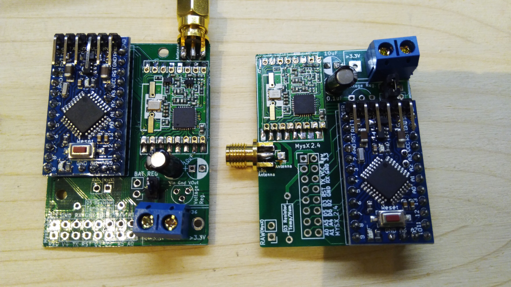
Rev9 vs Rev10 (inkl signing) rfm gw -
Yesterday I tested the new EasyPCB with RFM radio and hardware signing. Worked out as expected and I'm going to release all files soon.
I haven't tested the flash part yet but I'm hoping this is working as well.
This picture will be a part of a new video with me building my new RFM69 serial gateway using signing.
Anyone they can guess which issue I had when I took the photo?
Rev9 vs Rev10 (inkl signing) rfm gw@sundberg84 the RFM69 is soldered 180 degrees wrong on the new board :white_frowning_face:
-
@sundberg84 the RFM69 is soldered 180 degrees wrong on the new board :white_frowning_face:
@mickecarlsson interesting thought but no because the radio on rev9 isn't soldered in the image (but wrong rotated as you noticed). The hardware on that image is working. I added a HW radio without noticing so with the old code I just got no reply/Nack. I had to add the HW define.
-
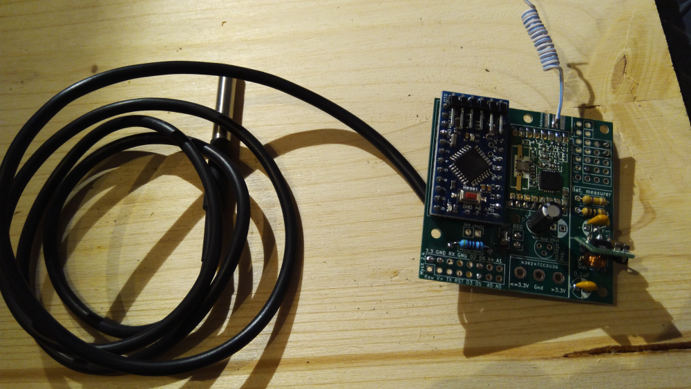
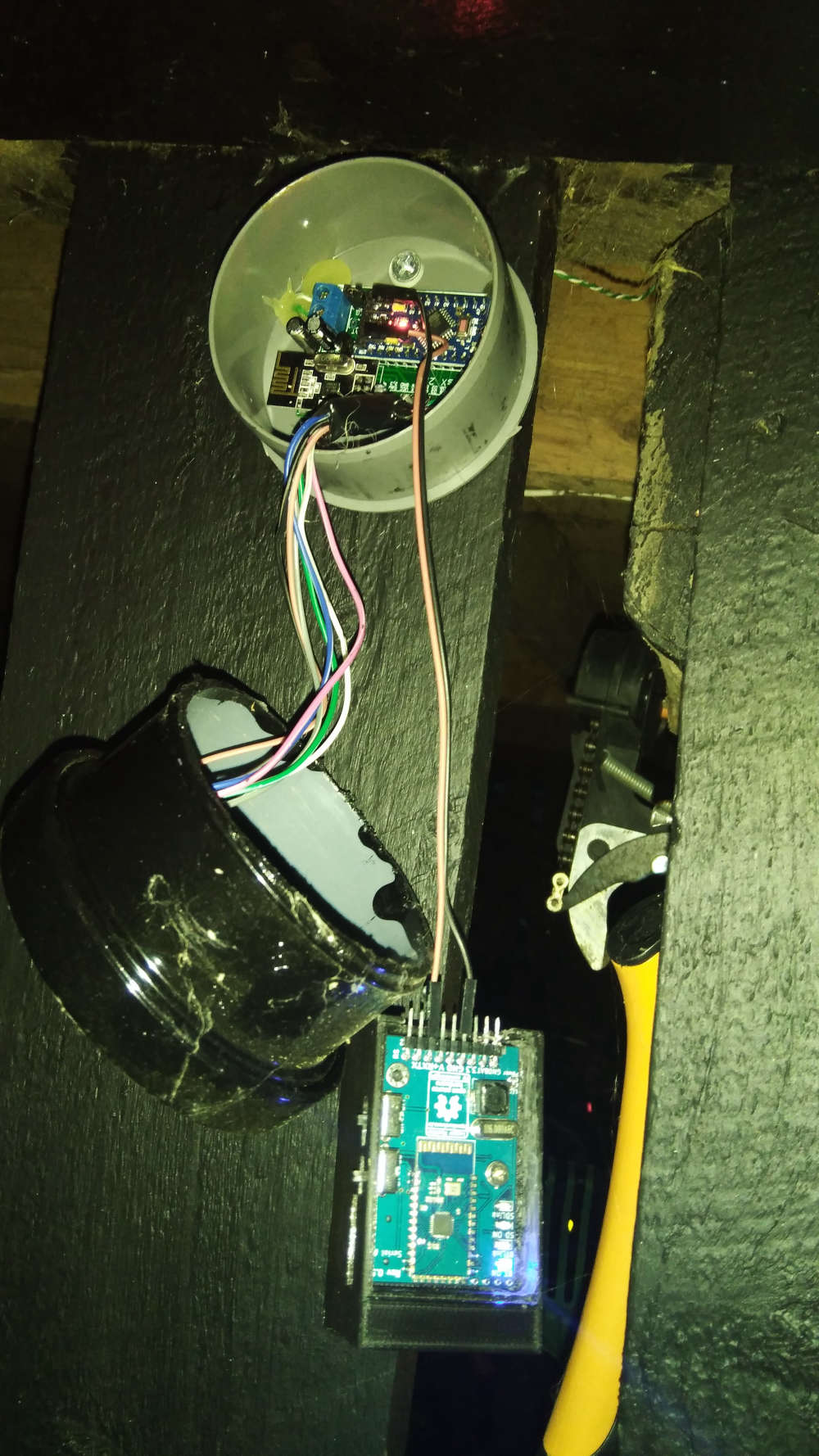
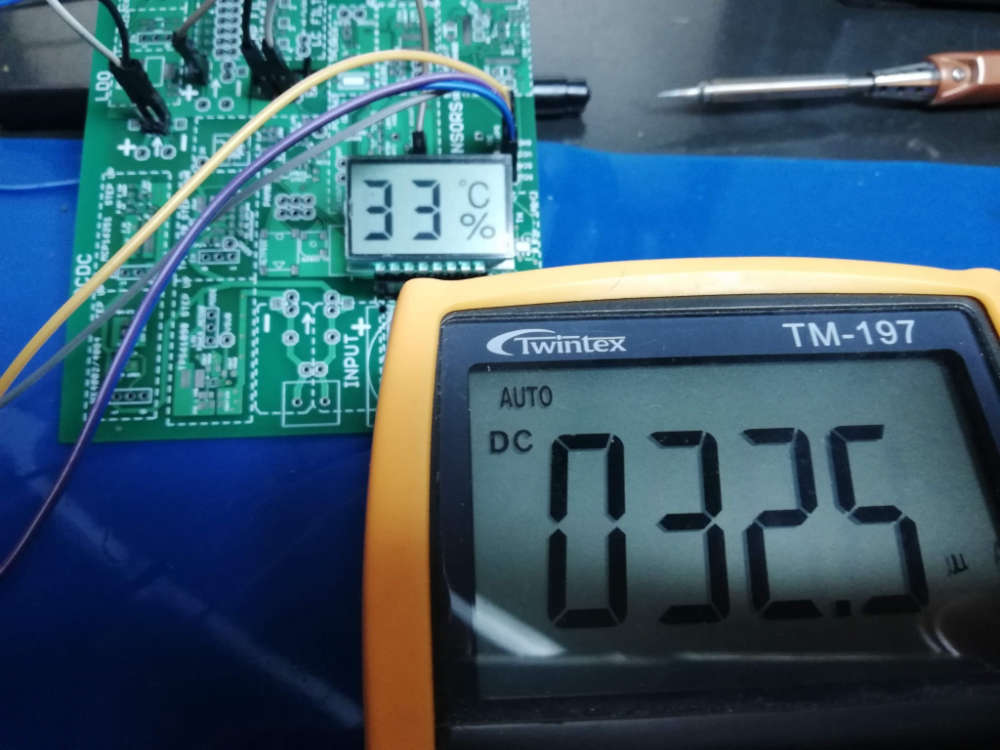
Redesigning my nodes in the RFM69 network to be signed using EasyPCB 10. Today it was my beer cooler node (because it's very important the beer temperature is secured). In the same time I'm implementing @gohan idea with two temp points (top and bottom).
-
Today I finally finished my second RGB LED lighting in the room. Next is the LED illumination of the perimeter of the bed. Under the bed, I want to place a motion sensor so that it reacts when I get out of bed at night.

you could use this under the bed:
It works like an infrared sensor (same three pins), but it does not need a line of sight. It just reacts to movement as this results in a disturbance in the emitted radio signal. Works very well on my clock :-)
The "high" value when movement is detected is not a full 5V, so I test the Out pin as an analog pin. Anything above 2.5V is an activation due to movement.
-
you could use this under the bed:
It works like an infrared sensor (same three pins), but it does not need a line of sight. It just reacts to movement as this results in a disturbance in the emitted radio signal. Works very well on my clock :-)
The "high" value when movement is detected is not a full 5V, so I test the Out pin as an analog pin. Anything above 2.5V is an activation due to movement.
@gertsanders many thanks!:raised_hands: This is very interesting, I did not previously hear about such a sensor.
I understand correctly that it can be placed in a wooden case and it can work through it? Since the tree does not reflect its waves.
If this is so, will not it respond to the movement of the bed frame or my movements when I'm on the bed?...:thinking_face: -
I tried some of those radar sensors and are very sensitive, they could detect even if you move in the bed. In addition I'd rather not sleep next to a 5 Ghz radar emitter 😅
-
So these radar motion sensors are actually quite impressive, the ones with just analog output only have 1 transistor, the rest of the circuit is formed by the pcb traces. Weird, but it works. They can be hacked (sawtooth wave for power) to give a distance reading instead of doppler. The signal processing is too much for an arduino, but it is doable.
The other ones actually use the same chip as the most common pir devices.
-
Suddenly my outdoor lightsensor stopped working. A good time to have a portal debugger. Everything seems fine in the log though... All ST:ok but for some reason it doesn't show up in domotocz.... Well that have to be tomorrows project.
-
Another node went down today... a repeater this time. Well... quickly a new one with additinal updates compared to old. (PA/Lna and Mysensors 2.3)
-
I made a working version of my test board with PCF85176 LCD driver, finally reaching some decently low current consumption for an always on display. There are still some possible gains to make with lower driver voltage, and with a more recent driver that should allow to go as low as 5uA.
-
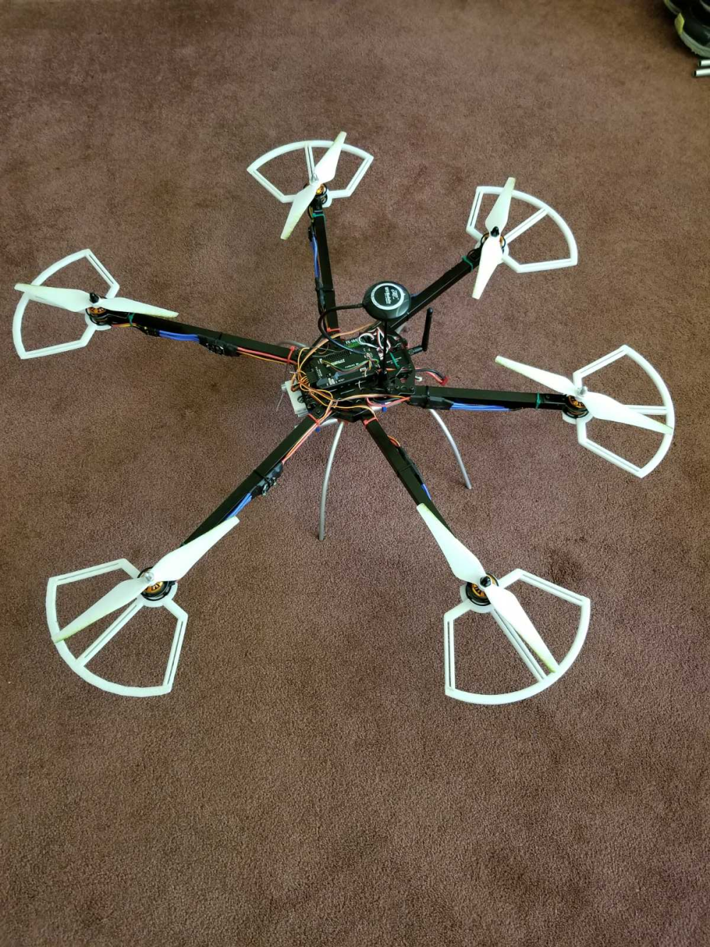
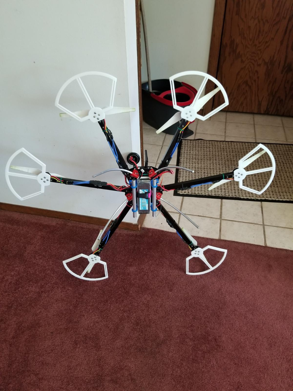
Though not MySensors related, I thought I'd post my latest build that has been consuming a lot of my time lately. This is the main reason I haven't been on the forum much lately. I bought a drone kit recently. Here are some pics from the initial assembly:

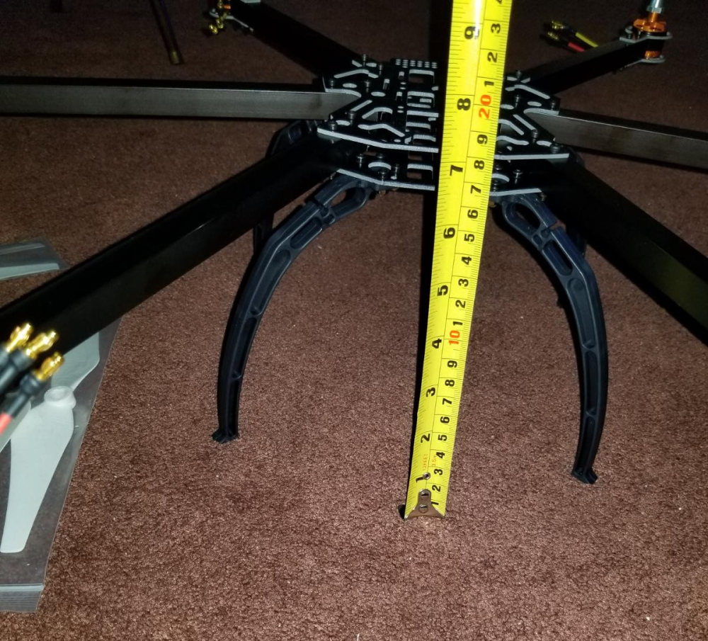
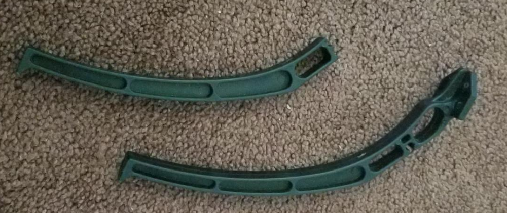
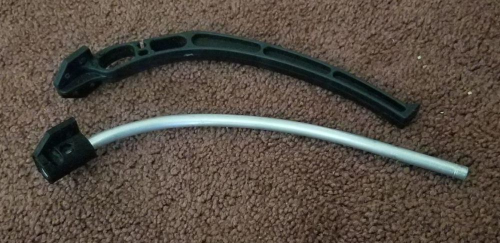
Since the initial build I have flown it and from a hard landing broken one of the cheap plastic legs that it came with. I designed a replacement with my 3D printer and some 1/4 inch aluminum rod.
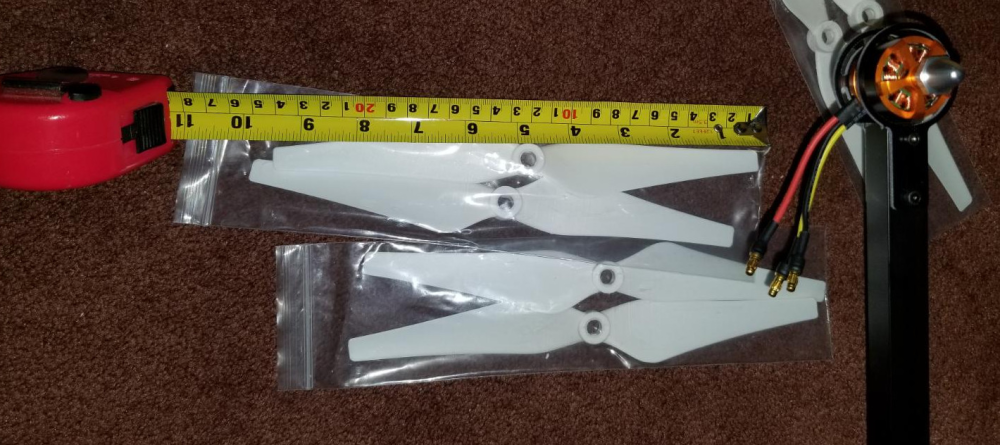
Here are some pics at it's current stage. I have designed and printed some prop guards and a few other add-ons:
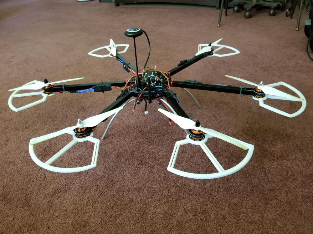
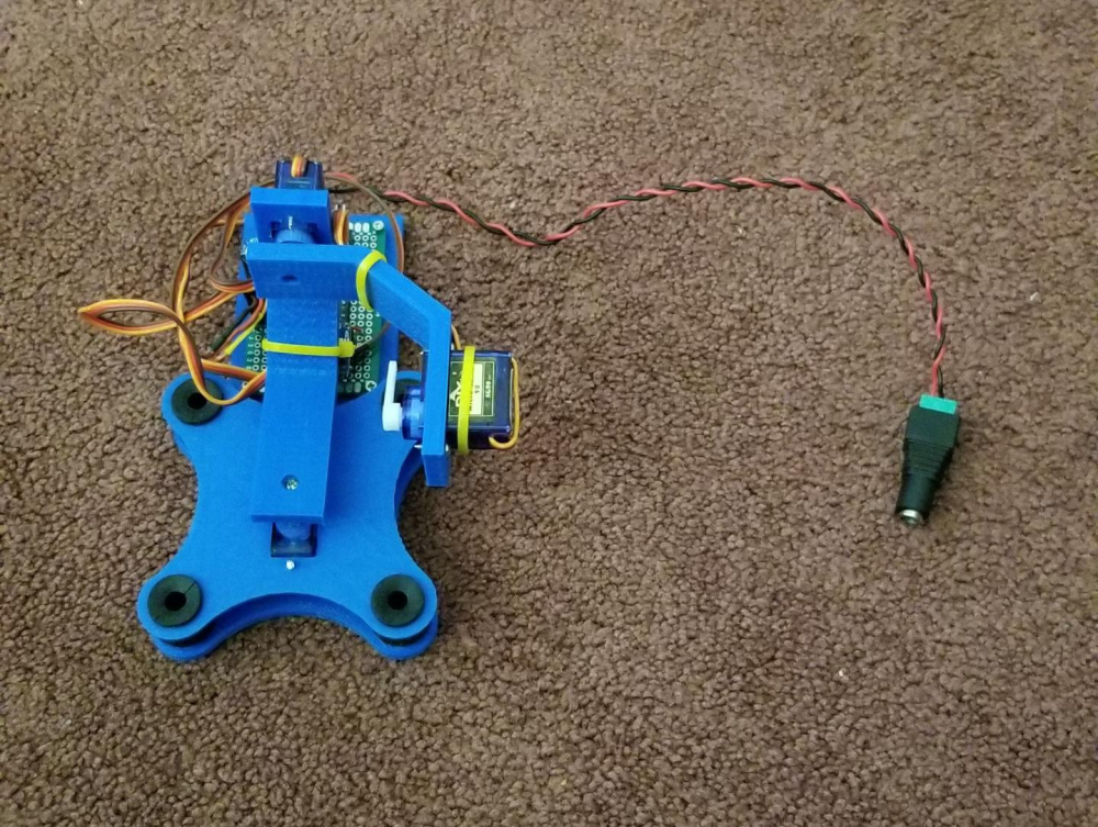
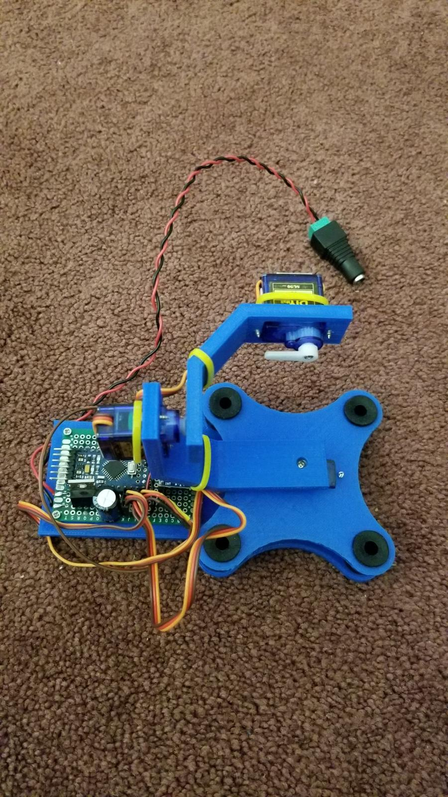
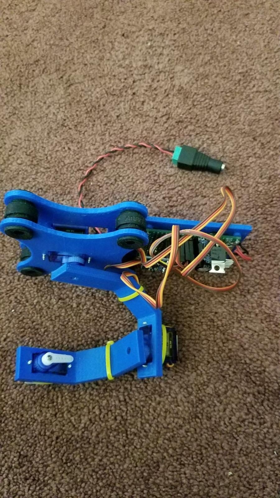
I have also designed and built a small servo based 3 axis camera gimbal. The controller was built using one of my spare 5 volt pro minis and an MPU-6050 accelerometer. Still working on the parts that will attach it to the drone, and I still need to pick up an FPV camera to attach to it, but a simple FPV cam is cheap.
-
@bjacobse it's the cheapest one on eBay with the software cheese on Linux. I think it's a replica on Andostar x500 so search Usb microscope Andostar and you will find.
@sundberg84
Thank you Sundberg for your help, I now have received my own microscope, a reply to your comments from 1 or 2 months ago