What did you build today (Pictures) ?

-
@bjacobse it's the cheapest one on eBay with the software cheese on Linux. I think it's a replica on Andostar x500 so search Usb microscope Andostar and you will find.
@sundberg84
Thank you Sundberg for your help, I now have received my own microscope, a reply to your comments from 1 or 2 months ago -
@andrew said in What did you build today (Pictures) ?:
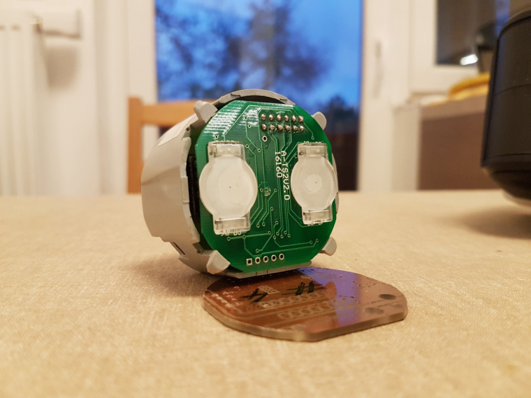
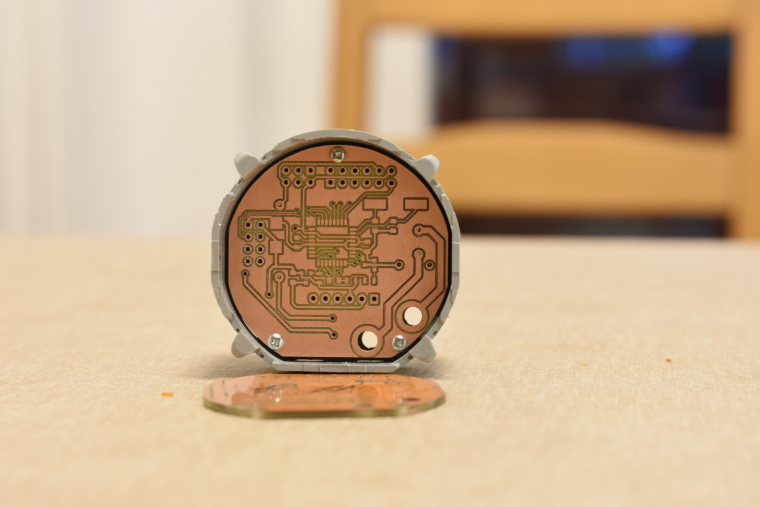
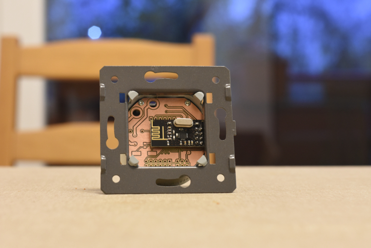
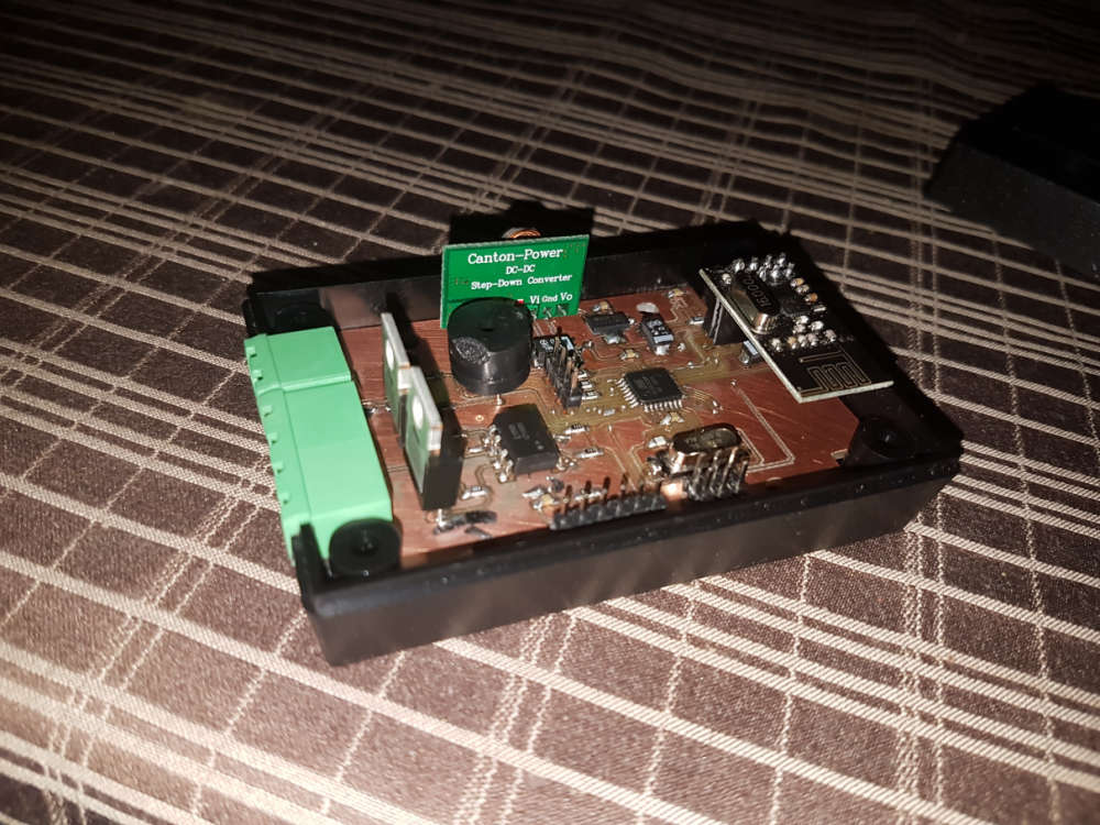
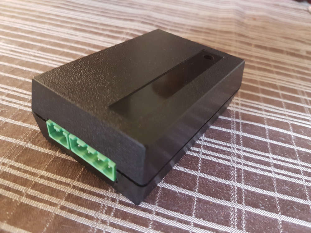
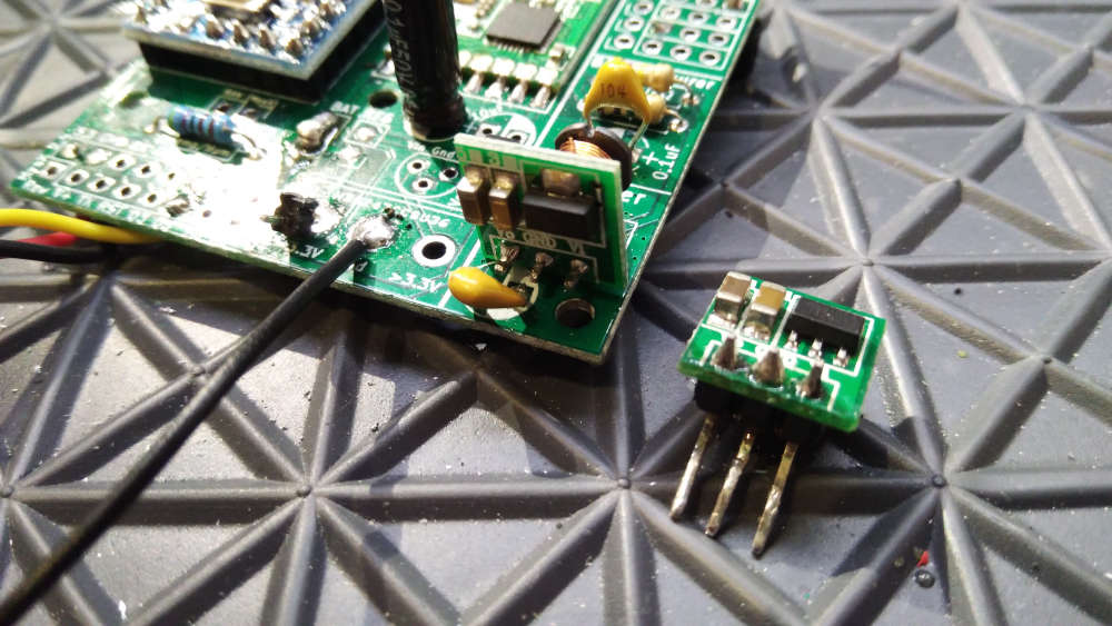
so, it is ready. I mean ready to SW development :) both the schematic and pcb design is now confirmed and fortunately theory meets the practice :)
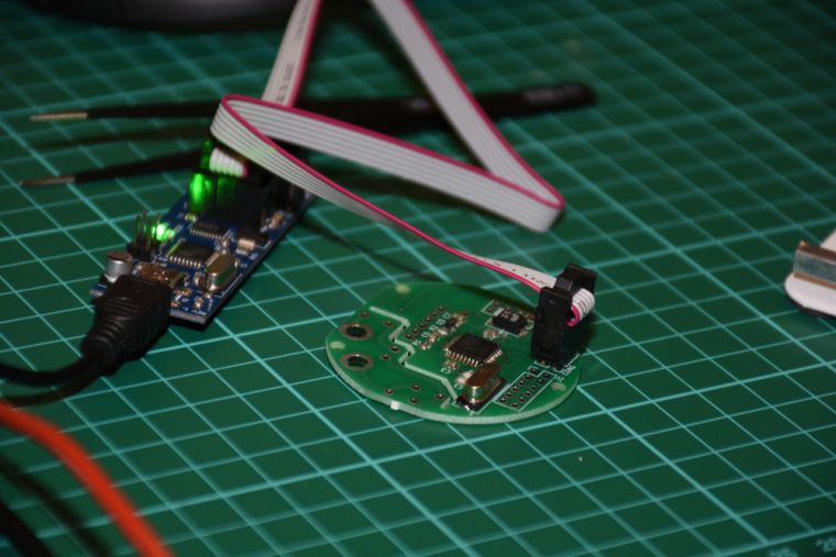
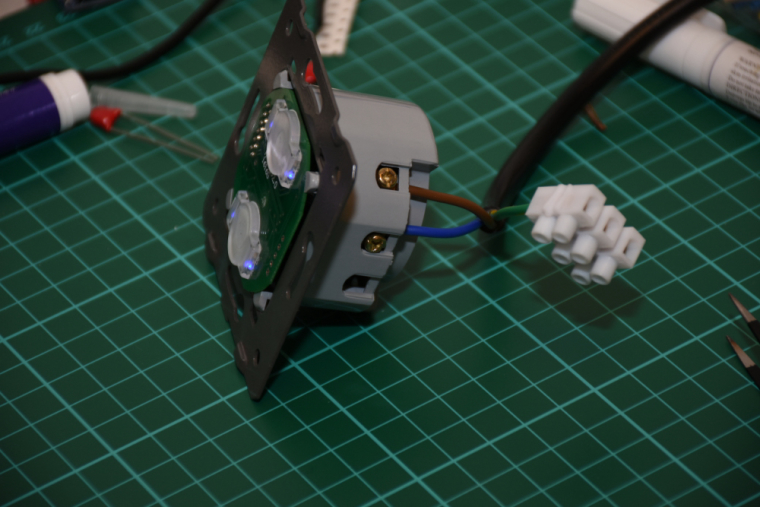
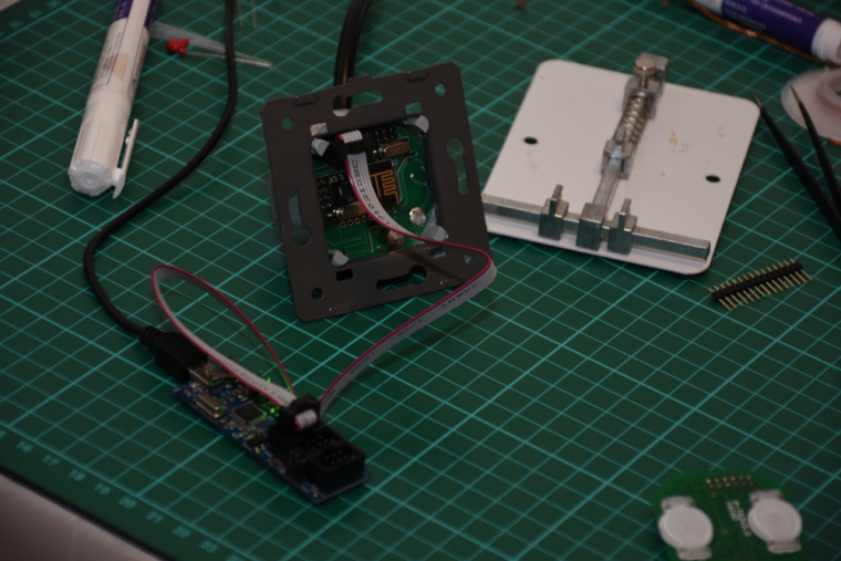
it is assembled, programmed, tested, everything works as expected.
I did not mount it to the wall so far (I'll need a controller and real actuators first), but there was no issue with the communication between two nrf modules (both with PCB antenna) from cca 6 meter distance + 2 walls (10 cm brick) in between.the touch panel's firmware will be enhanced as well as the controller's firmware, at the moment the touch sensing is reliable and a PoC code run on both of them for testing/debugging purposes. for the controller board I'm collecting additional information for the development on the following link:
https://forum.mysensors.org/topic/8831/which-sensor-and-msg-type-for-switch-dimmer-node-sender-only -
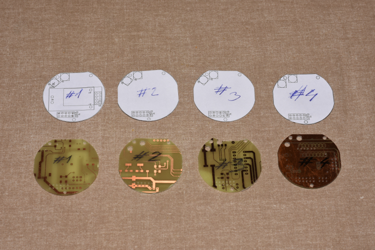
@andrew have you also designed the power board or do you reuse the livolo's one?
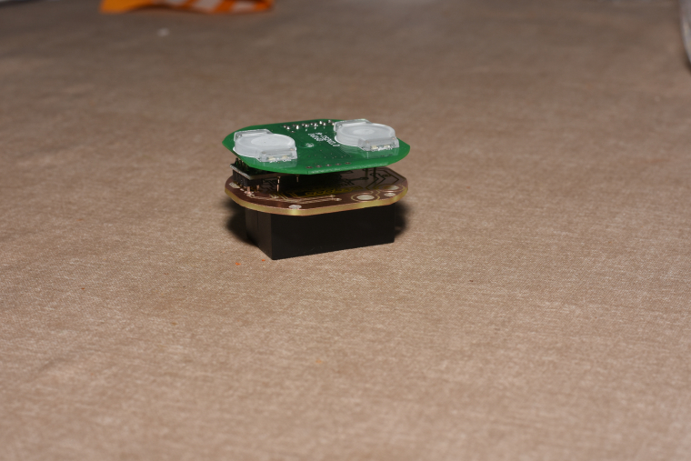
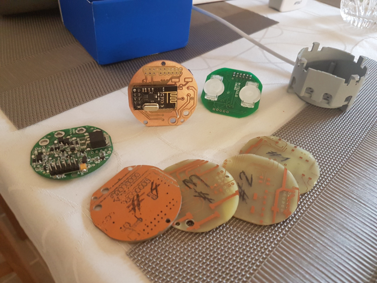
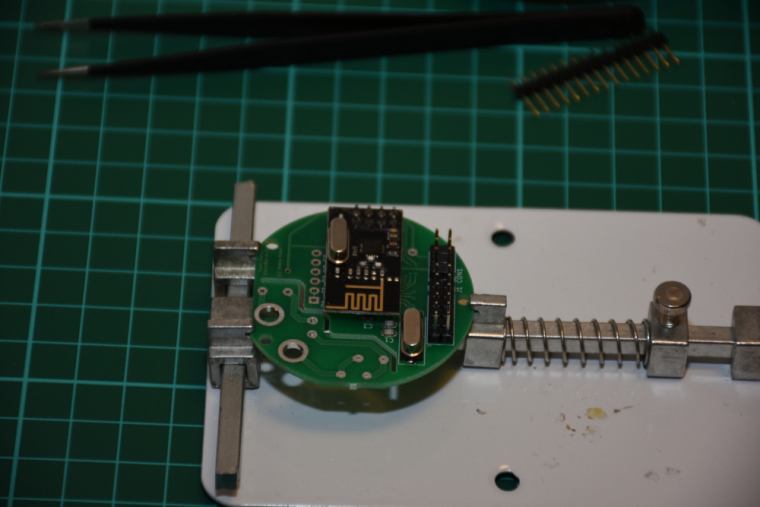
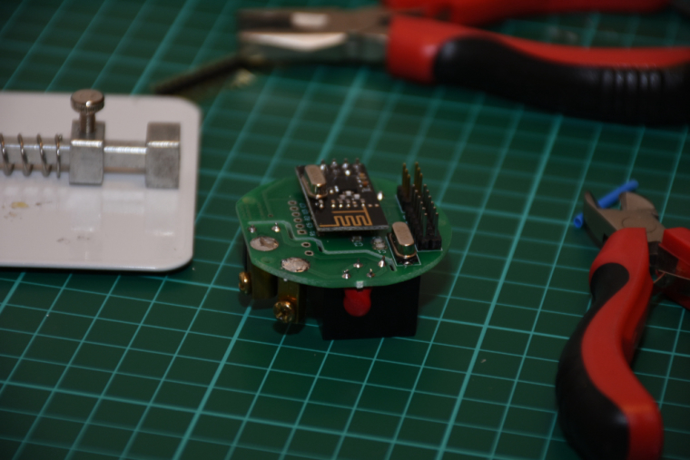
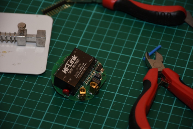
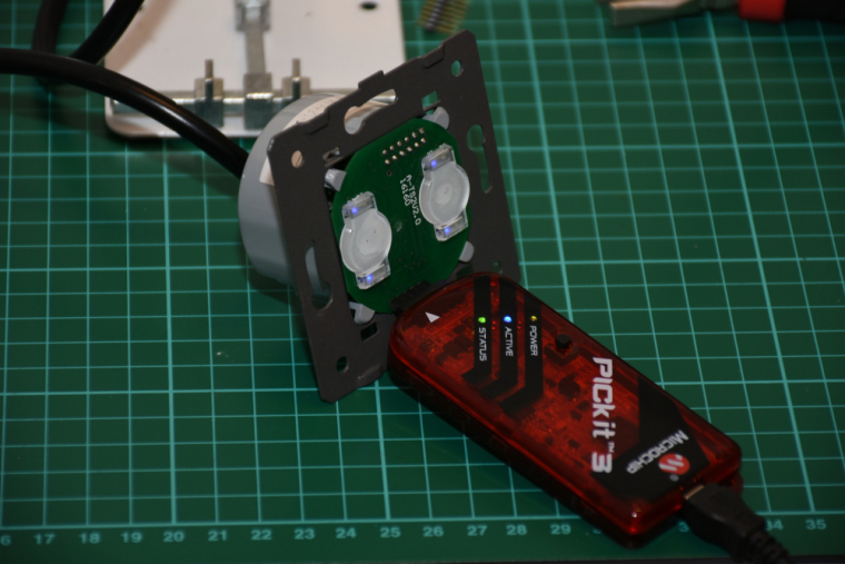
@jeremushka I reused the top PCB (the touch panel) with its original microcontroller, but with a custom firmware. the bottom PCB was fully replaced with my own designed version. this includes the power supply with additional protections, atmega328, atsha and nrf radio.
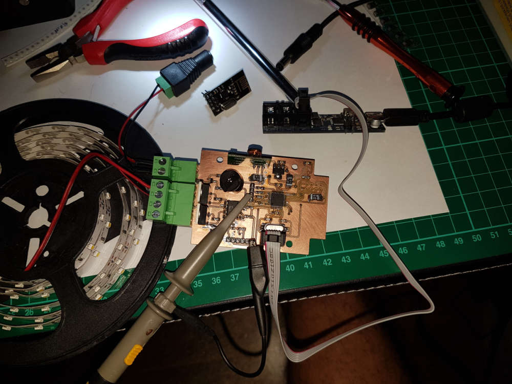
it is running very well on my desk, but I was super busy in the past months so it is not yet installed to the wall.in parallel I also had to finish its opposite side, the controller at the lamp. it is also ready for final installation, I just need time for that :)
-
The other day I finished the first version of the PCB for my system of protection against water leakage. It will have two automatic ball valves, six leakage sensors with wire breakage monitoring and in the future I plan to connect it to the Mysensors.

Here is a prototype collected with the help of Arduino Pro Mini. Arduino Uno is just nearby, but not connected. Do not pay any attention to him. :)

-
The other day I finished the first version of the PCB for my system of protection against water leakage. It will have two automatic ball valves, six leakage sensors with wire breakage monitoring and in the future I plan to connect it to the Mysensors.
Here is a prototype collected with the help of Arduino Pro Mini. Arduino Uno is just nearby, but not connected. Do not pay any attention to him. :)
@vladimir I gather you meant motorised ball valves rather than automatic, the automation being on the processor.
When you refer to leakage, is this to react to pipes potentially bursting or an external failure such as drainage failure in a cellar? -
@vladimir I gather you meant motorised ball valves rather than automatic, the automation being on the processor.
When you refer to leakage, is this to react to pipes potentially bursting or an external failure such as drainage failure in a cellar? -
@zboblamont Yes, it is, motorized ball valves.
I meant the reaction to the breakthrough of pipes or flexible connections of sanitary ware.@vladimir Ok understood, washing machine hose failure or plumbing seals etc..
Had also considered incorporating leak detection after twice flooding out my bathroom (water softener cycle discharged externally normally - doesn't work so well at -20), ultimately solved by some overflow plumbing to internal drainage.Still considering leak detection as a failsafe, but was looking at monitoring internal and external pressure and flow as well as conductivity at three separate areas. The idea was to similarly initiate shutdown of a motorised valve (for the entire house), or close down the supply pump for an external burst, so a little more complicated, but hence the curiosity.
For surface water detection I was looking at either fixed stainless stud contacts on the tiled floors, or mounting 3 on a plate like a tripod, as it should be more resistant to corrosion than standard rain sensor plates. -
@vladimir Ok understood, washing machine hose failure or plumbing seals etc..
Had also considered incorporating leak detection after twice flooding out my bathroom (water softener cycle discharged externally normally - doesn't work so well at -20), ultimately solved by some overflow plumbing to internal drainage.Still considering leak detection as a failsafe, but was looking at monitoring internal and external pressure and flow as well as conductivity at three separate areas. The idea was to similarly initiate shutdown of a motorised valve (for the entire house), or close down the supply pump for an external burst, so a little more complicated, but hence the curiosity.
For surface water detection I was looking at either fixed stainless stud contacts on the tiled floors, or mounting 3 on a plate like a tripod, as it should be more resistant to corrosion than standard rain sensor plates.@zboblamont
water leak/flooding detection,
I propose to get some stainless conductive wire, like this: https://www.adafruit.com/product/603
and then add 2 parallel wires on tape, and tape this to the floor, besides the dishwasher -
@zboblamont
water leak/flooding detection,
I propose to get some stainless conductive wire, like this: https://www.adafruit.com/product/603
and then add 2 parallel wires on tape, and tape this to the floor, besides the dishwasher@bjacobse Interesting concept, and product, not so sure about the tape idea over a mechanical fix, the tape's behaviour in a wet or moist environment could prove unpredictable.
Tie/clamp this to a stud, or to a stainless rod projected to floor level might solve the corrosion issue with copper wire though.... -
@bjacobse Interesting concept, and product, not so sure about the tape idea over a mechanical fix, the tape's behaviour in a wet or moist environment could prove unpredictable.
Tie/clamp this to a stud, or to a stainless rod projected to floor level might solve the corrosion issue with copper wire though....@zboblamont @bjacobse
I plan to make the leakage sensors waterproof, with outwardly exposed contacts made of stainless steel. I plan to lift the contacts 1-2mm from the floor so that when washing floors, when the floor is just a little wet sensor did not work. I really like the sensors from Xiaomi.


I ordered for the sample here are such cases from China:1 - 31х10mm


2 - 61х20mm
-
The project of today is not yet connected with Mysensors.
This is a light relay with an IR receiver for the spotlight illuminating the backyard of my friends' house.
In the dark, the relay can be switched off from the remote control (to block the activation of the relay). If the remote is far away from you, then the lock can be removed with the searchlight switch by restarting it.
To understand if the relay is locked, there is a red LED on the case.


-
Anyone spots the differens? One booster draws 21mA sleeping and the other 13uA.
(I don't).
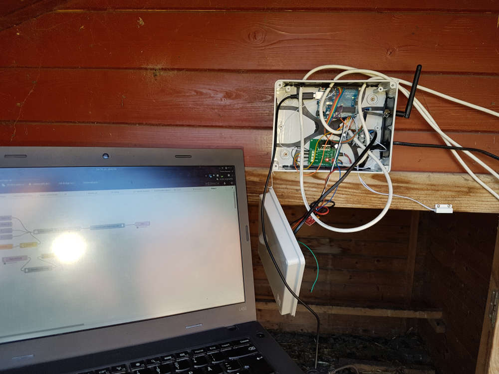
Controller: Proxmox VM - Home Assistant
MySensors GW: Arduino Uno - W5100 Ethernet, Gw Shield Nrf24l01+ 2,4Ghz
MySensors GW: Arduino Uno - Gw Shield RFM69, 433mhz
RFLink GW - Arduino Mega + RFLink Shield, 433mhz -
Anyone spots the differens? One booster draws 21mA sleeping and the other 13uA.
(I don't).
@sundberg84 Easy, one is disconnected... :joy: At 90 degrees? :stuck_out_tongue_winking_eye:
-
Anyone spots the differens? One booster draws 21mA sleeping and the other 13uA.
(I don't).
@sundberg84 Different SMD capacitors?
-
Anyone spots the differens? One booster draws 21mA sleeping and the other 13uA.
(I don't).
@sundberg84 Which booster is this anyway it looks better made than many I've seen available ?
-
@sundberg84 Which booster is this anyway it looks better made than many I've seen available ?
@zboblamont its the one from mysensors store. I bought 10 and 8 of them is working.
-
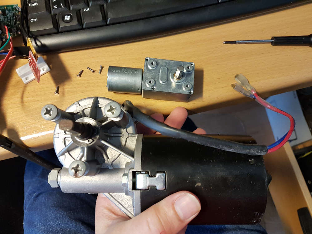
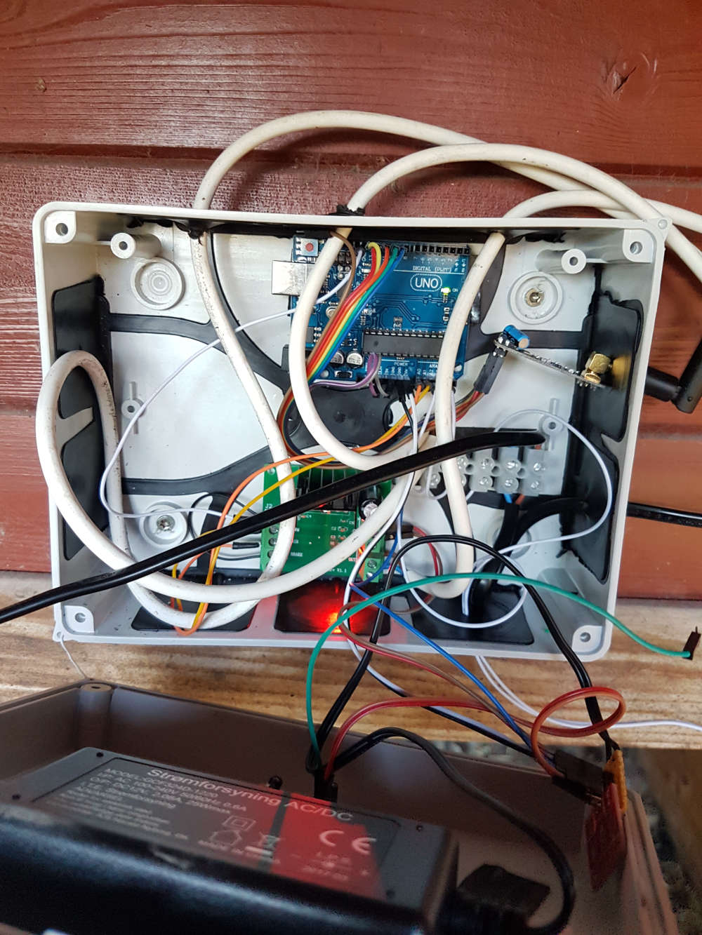
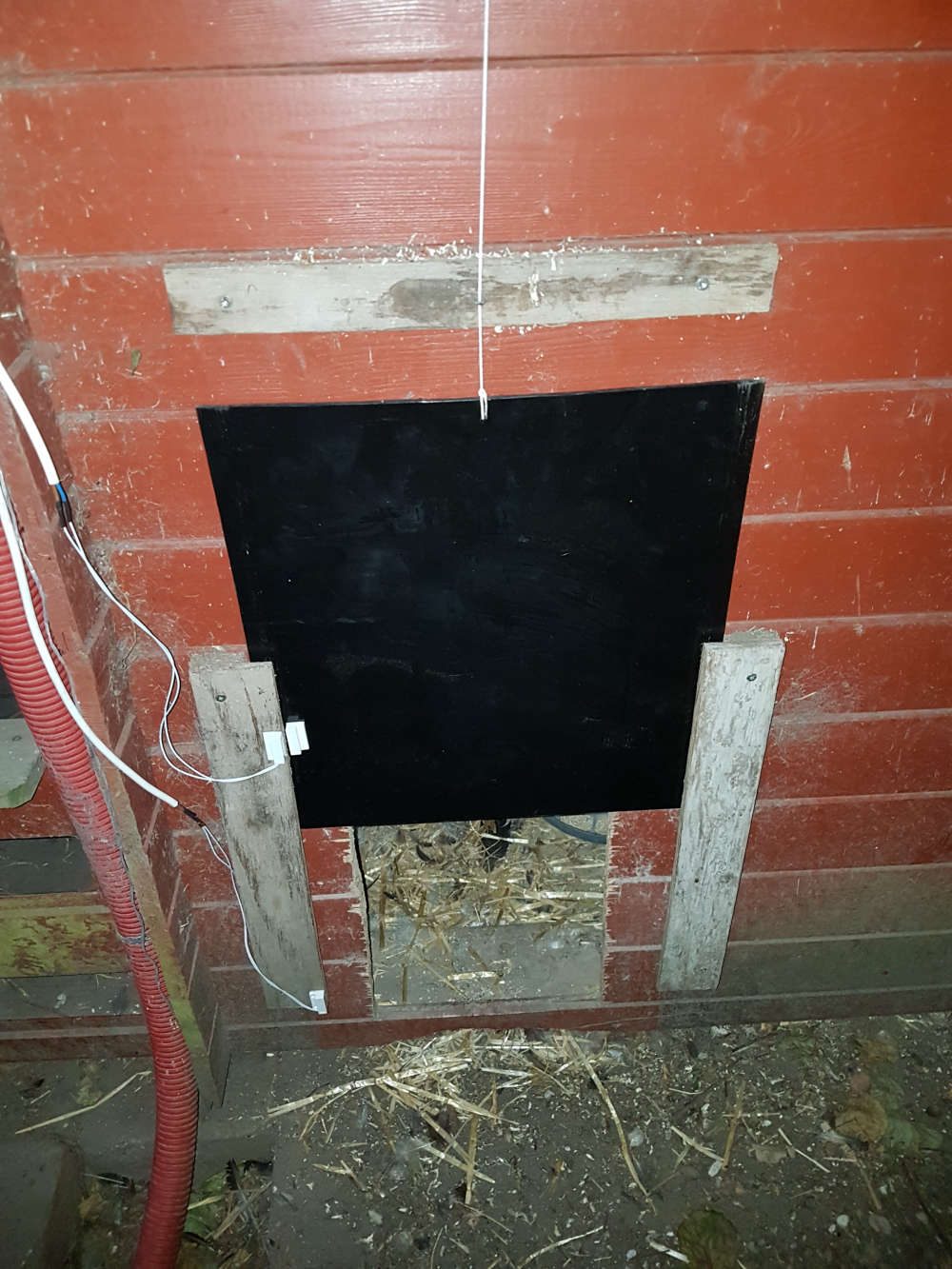
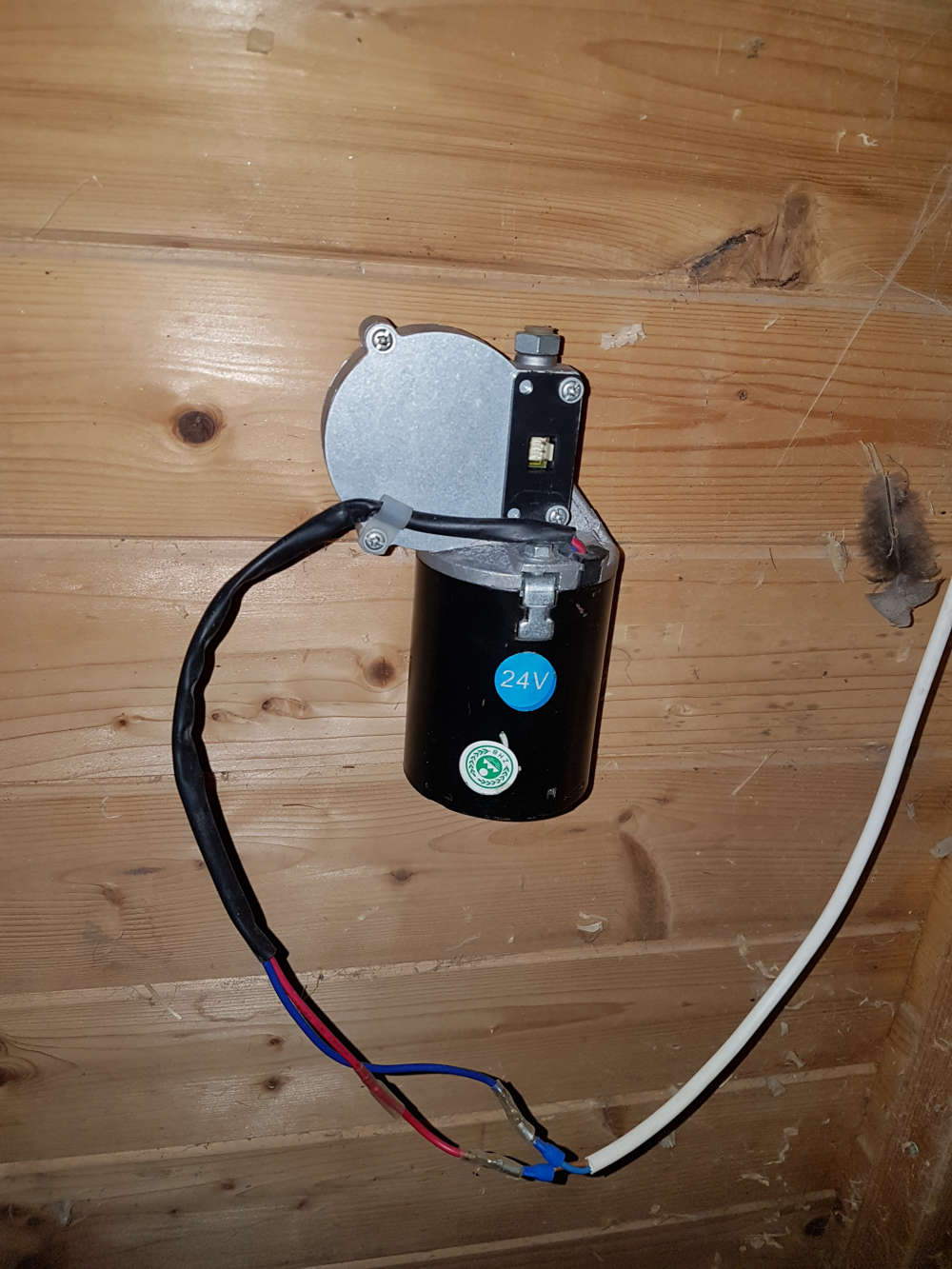
Finally I finished my chicken coop door opening thingie :) A build that has taken way to much time to complete, and a few different directions.
Just as I was ready to install the thing, I discovered that the DC motor that I had bought for this, couldn't lift the gate. So I had to go scrap hunting, to find a larger motor for it.. Luckily I had a 24V motor from a broken garageport opener which chould be used at 12V.
Control box above the door, includes a PIR sensor in the lid.
the gate, a sheet of 3mm black acrylic "glass". I had a couple of reed relays in the parts bin, so I use those to detect positions of the gate.
The motor on is placed on the inside of the wall.
Field update of the firmware.. Should probably reflash the bootloader, to mysboot, so I can do it OTA..
-
and of course a small video of the in action
-
and of course a small video of the in action
-
and of course a small video of the in action