What did you build today (Pictures) ?

-
@sindrome73 said in What did you build today (Pictures) ?:
I'm sorry if I can, but what kind of sensor are you using to detect water ?? I would like to do something like that but with an Arduino pro !!
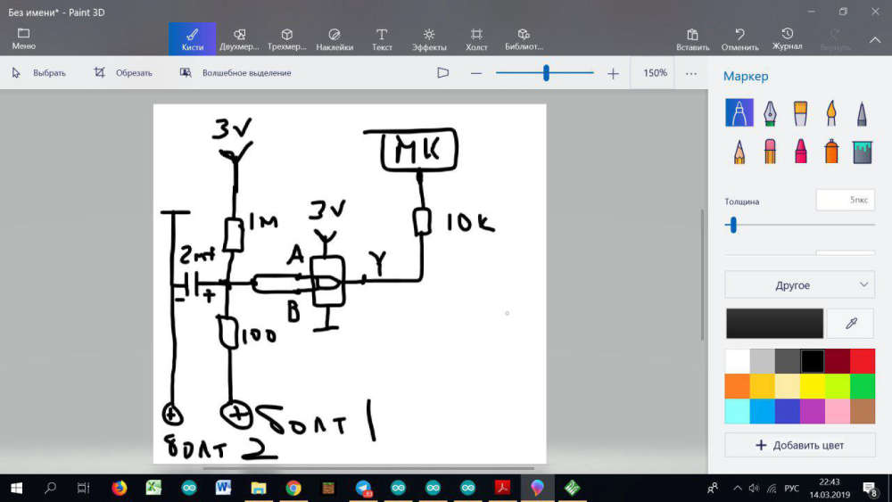
Used by SN74LVC1G00. Recently I was asked for this scheme in myssensor_rus telegram-chat. I drew it by hand in PAINT, I can offer it to you. I apologize, but nevertheless it is a scheme :)
-
@berkseo thanks for the scheme. but therefore don't use a sensor ?? i'm sorry noni and clear how do you detect the presence of water ...
-
@sindrome73 the sensor is the two screws. Without water, the elevtrical between the screws is very high. With water, the electrical resistance is lower.
@mfalkvidd ok now I understand, and then commands an Arduino or other. thank you
-
@zboblamont said in What did you build today (Pictures) ?:
umbillicals
It is rubber hoses with metal braiding.
But rubber degrades and this equipment is the most common cause of water leakage.@kimot The elastomers used are resilient and will last decades from new, never seen one burst yet. Most folks remodel bathrooms every 5-10-20 years and should replace these at the same time, which was why I chuckled at the 40 years.
With the technology and battery longevitity available nowadays, they are certainly a handy device to have where problems have occured or may.
-
@sindrome73 said in What did you build today (Pictures) ?:
I'm sorry if I can, but what kind of sensor are you using to detect water ?? I would like to do something like that but with an Arduino pro !!
Used by SN74LVC1G00. Recently I was asked for this scheme in myssensor_rus telegram-chat. I drew it by hand in PAINT, I can offer it to you. I apologize, but nevertheless it is a scheme :)
-
@berkseo
Clever idea to use SN74LVC1G00 as while both inputs are same voltage it only consume ICC = 10uA (10 mircoA) in whole voltage range 1.65V -5,5V@bjacobse said in What did you build today (Pictures) ?:
Clever idea to use SN74LVC1G00 as while both inputs are same voltage it only consume ICC = 10uA (10 mircoA) in whole voltage range 1.65V -5,5V
Power consumption of the entire device in a sleep - less than 3 mircoA.
-
@berkseo
Clever idea to use SN74LVC1G00 as while both inputs are same voltage it only consume ICC = 10uA (10 mircoA) in whole voltage range 1.65V -5,5V@bjacobse said in What did you build today (Pictures) ?:
@berkseo
Clever idea to use SN74LVC1G00 as while both inputs are same voltage it only consume ICC = 10uA (10 mircoA) in whole voltage range 1.65V -5,5VNot when when you have a low power comparator available that runs with only 0.5µA...
-
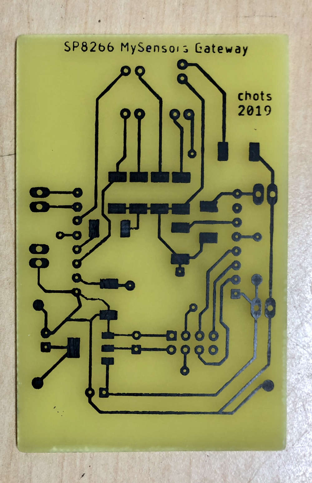
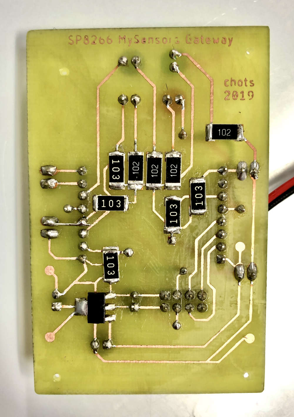
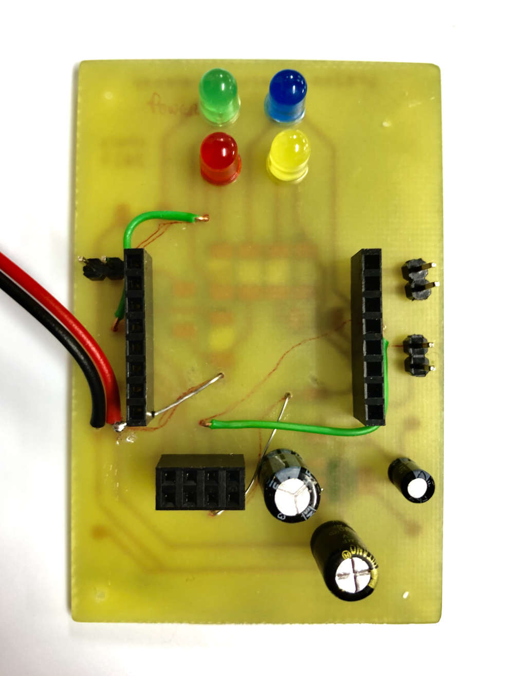
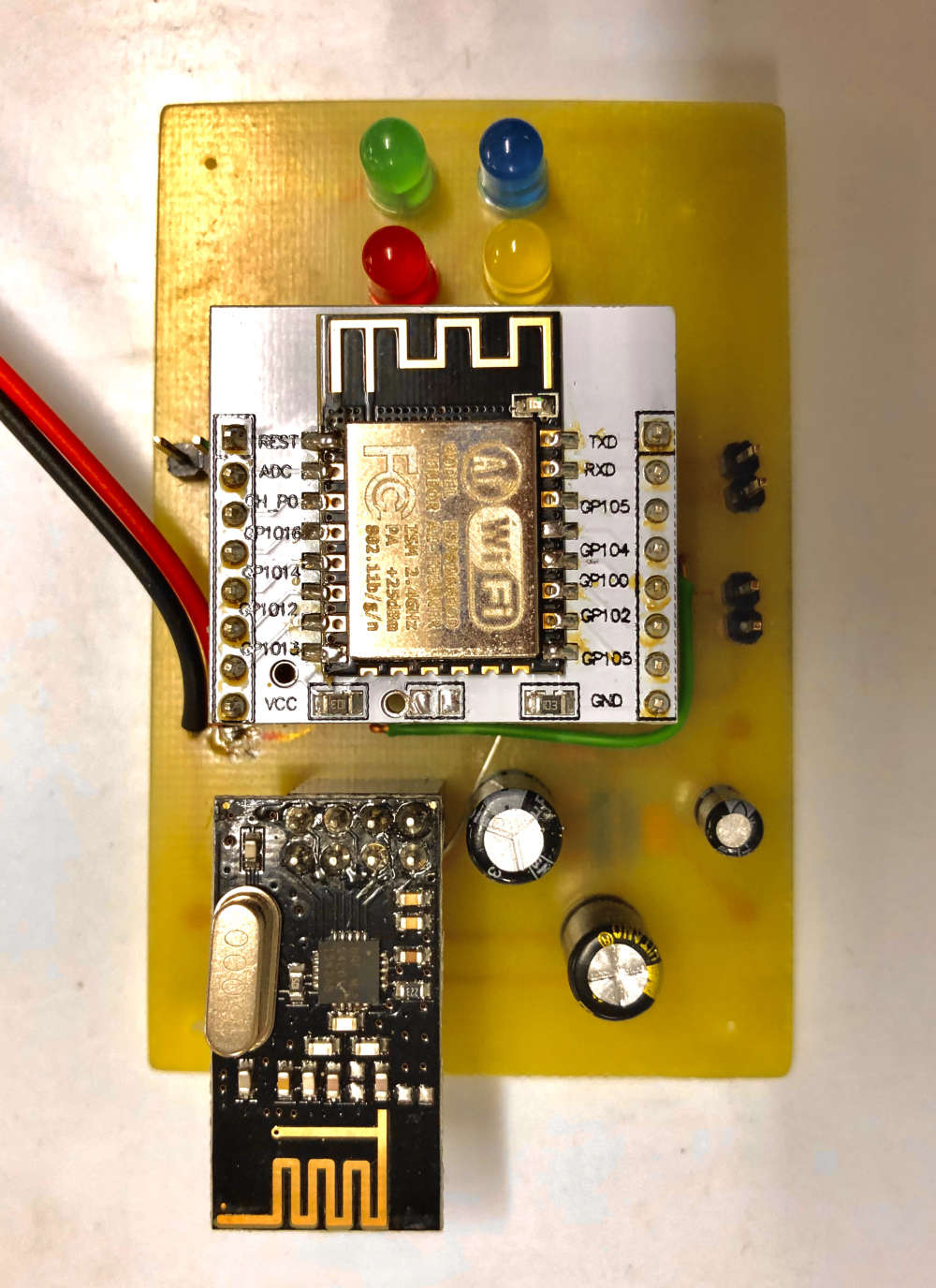
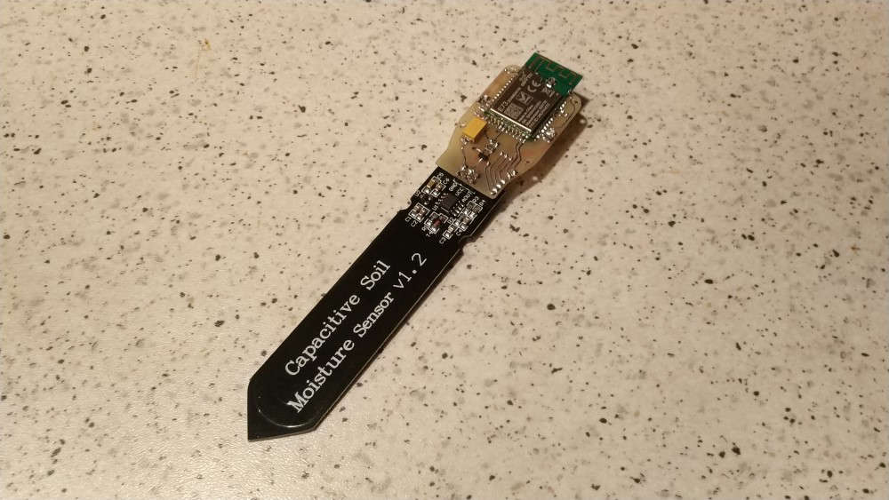
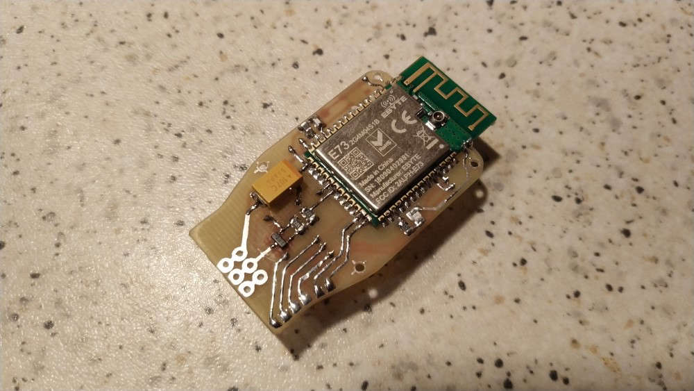
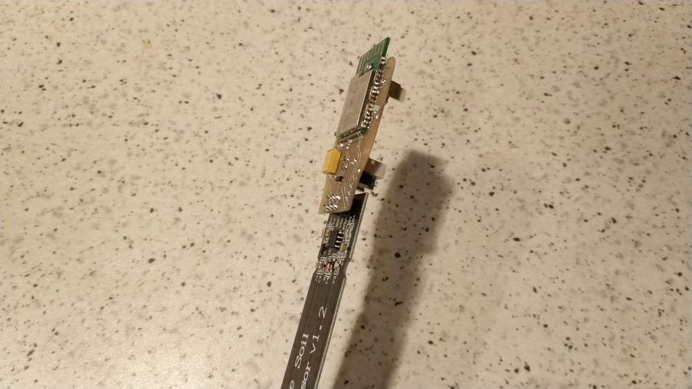
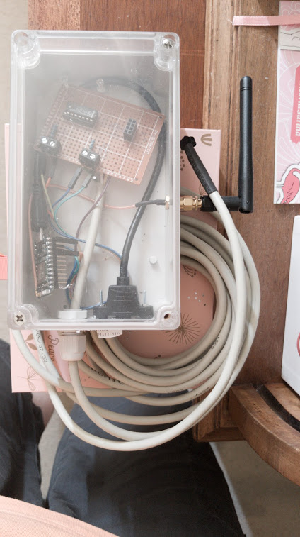
Wireless expansion module for very cheap soil moisture sensor from Aliexpress :)
-
Finally the round-tuit UPS got built after the last power cut clobbered the Controller/Gateway system, lesson learned...
Meanwell AD-55A, 7.2Ah Acid gel battery, two usb 5v buck converters, a spare socket for raw volts, and a 15 euro IP66 box from the local shops.. Some drilling and filing to the lid, couple of brackets, spare bolts, banding, soldering and hot glue...
A bit bulky, but disappears in a void under the stairs, two tiny drill holes let the buck converter leds shine threw...
No monitoring as yet, but sailed through a power cut this morning and the Pi didn't skip a beat.. First up is the Pi's RTC then can put the cover back on the Controller...
![0_1563789698294_20190721_074129[1].jpg](/assets/uploads/files/1563789705402-20190721_074129-1-resized.jpg)
![0_1563789869238_20190722_001114[1].jpg](/assets/uploads/files/1563789875508-20190722_001114-1-resized.jpg)
-
Finally the round-tuit UPS got built after the last power cut clobbered the Controller/Gateway system, lesson learned...
Meanwell AD-55A, 7.2Ah Acid gel battery, two usb 5v buck converters, a spare socket for raw volts, and a 15 euro IP66 box from the local shops.. Some drilling and filing to the lid, couple of brackets, spare bolts, banding, soldering and hot glue...
A bit bulky, but disappears in a void under the stairs, two tiny drill holes let the buck converter leds shine threw...
No monitoring as yet, but sailed through a power cut this morning and the Pi didn't skip a beat.. First up is the Pi's RTC then can put the cover back on the Controller...
-
@zboblamont is the battery and switch mode psu just in parallel? Or do you have a switchover / charge circuitry?
@tbowmo The Meanwell AD-55A is a purpose made 12v UPS type with all controls onboard. There is an optional version with monitoring brought out to a connector block, but I couldn't find one.
The photo angle is misleading - Channel 1 +/- is to load, Channel 2 +/- is trickle charge to battery, power failure switches seamlessly to the battery as source..
It's a fairly comprehensive arrangement with an array of safety features including battery protection, eg - If during power failure you disconnect the battery, it's reconnection will not restore load power, and resets only on mains supply.
Case ventilation made using a metal bracket with a matrix of holes as a drill through template so it looks neat, but as the PSU barely gets warm to the touch it proved to be overkill. -
Finally the round-tuit UPS got built after the last power cut clobbered the Controller/Gateway system, lesson learned...
Meanwell AD-55A, 7.2Ah Acid gel battery, two usb 5v buck converters, a spare socket for raw volts, and a 15 euro IP66 box from the local shops.. Some drilling and filing to the lid, couple of brackets, spare bolts, banding, soldering and hot glue...
A bit bulky, but disappears in a void under the stairs, two tiny drill holes let the buck converter leds shine threw...
No monitoring as yet, but sailed through a power cut this morning and the Pi didn't skip a beat.. First up is the Pi's RTC then can put the cover back on the Controller...
-
@zboblamont Do you have any more info on this? Components and schematic? I am looking to do this as well as Florida is now fully into storm season.
@wergeld Sure, but this is where I first read about it as part of a comparative link text when I was trying to decide on a UPS after a series of outages (frequent out here in the sticks).
The dual buck converters were the only real variation (in case one blew). Following kind advice after querying buck converters on this forum, this is the type I ordered but off eBay, but this is very similar layout... link text
I should explain that I would have gone for a commercial UPS had a decent USB supply been quoted, but the reality is that for most the USB is of secondary consideration to backup mains...
I gets interesting when you consider the actual Ah capacity before the battery low cutout operates, I reckon well in excess of 12 hours...
Have fun... ;) -
not with mysensors, but could have been: CNY70 water sensor meter (rotating wheel) with extended wifi range, the heart of it is a Particle Photon pushing to domoticz
-
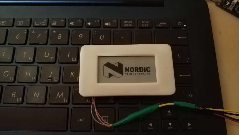
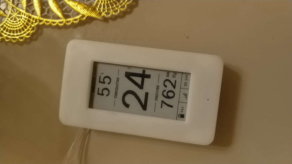
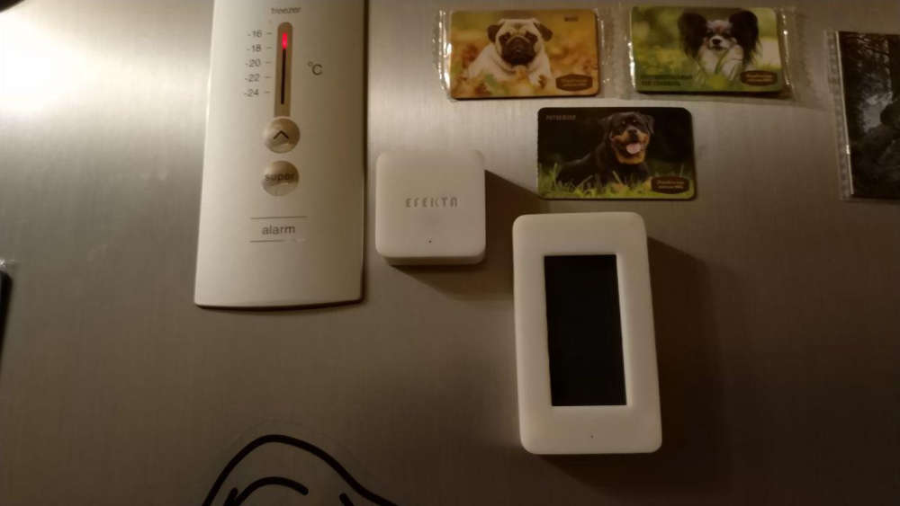
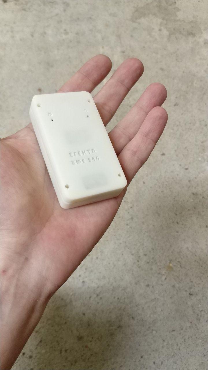
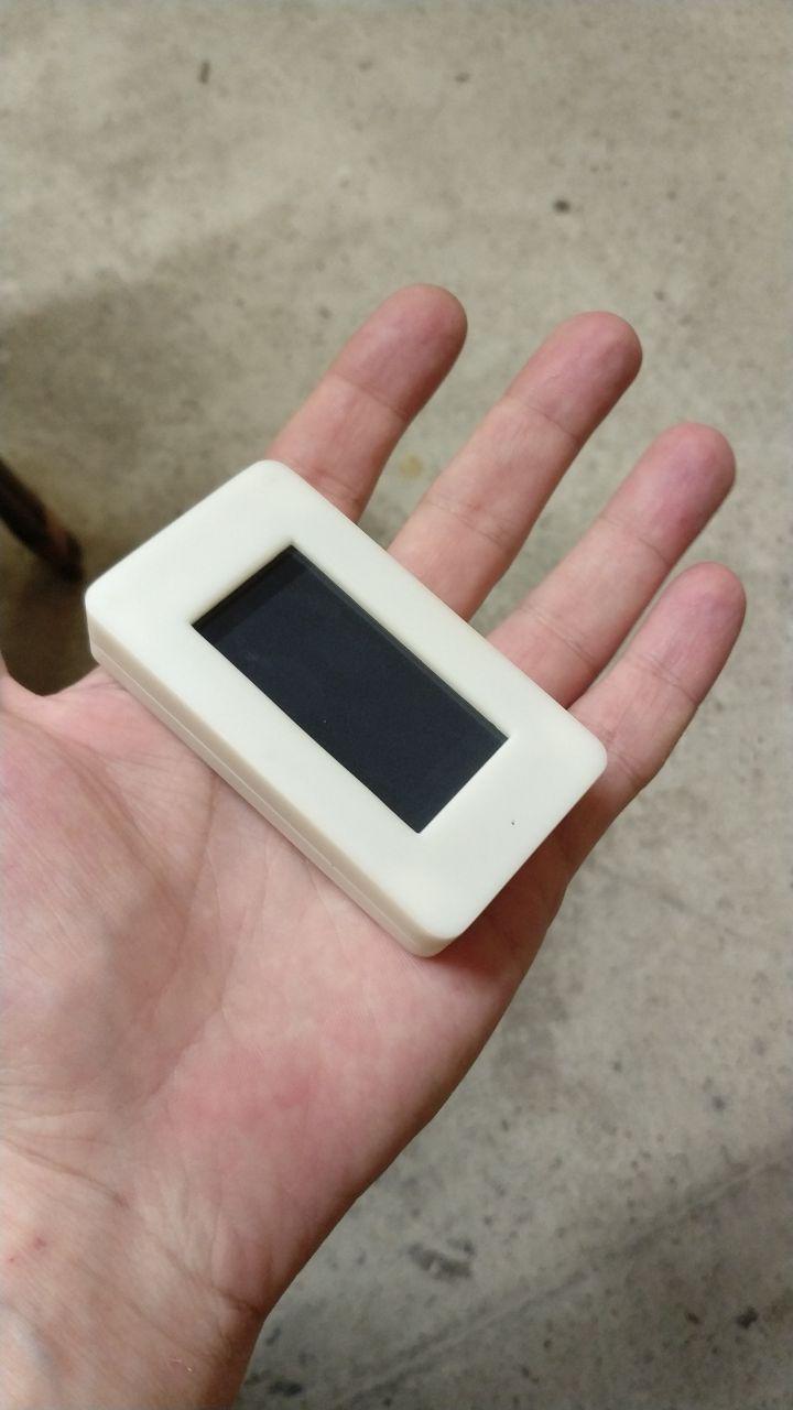
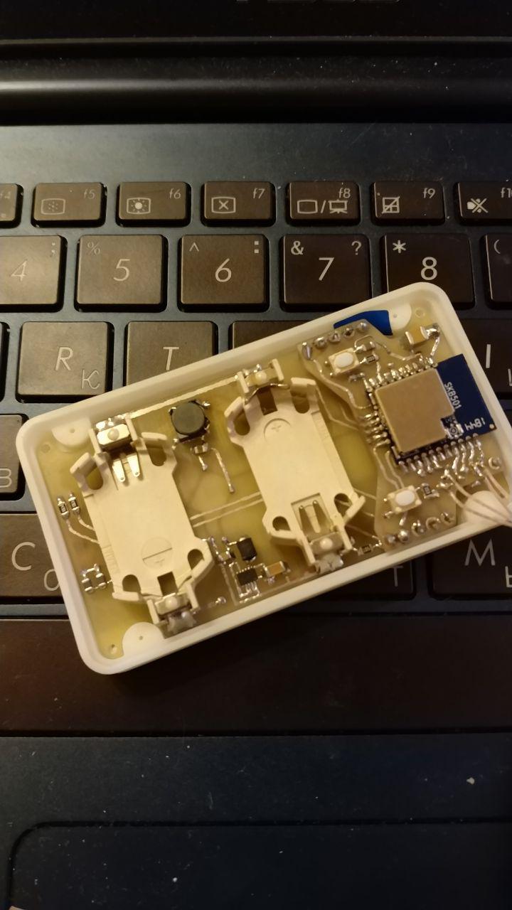
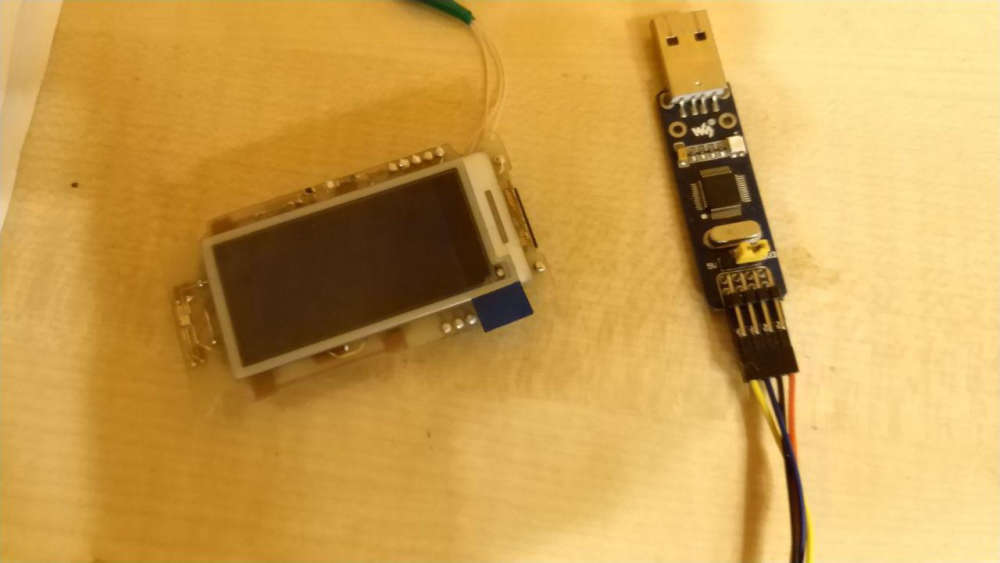
Today I finished printing the case. Turned out to node with sensor bme280 and e-ink display, running on nRF52840 from SKYLAB
In one of the photos still have the sensor with bme280 working on nrf52840 from EBYTE. ...This is the previous project.
upd.

-
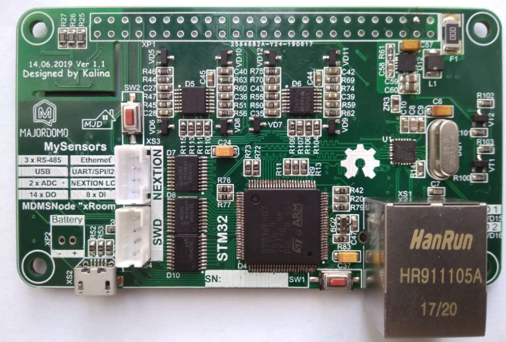
I have soldered the first sample of "xRoom" board.
TODO: testing and detail description of the project))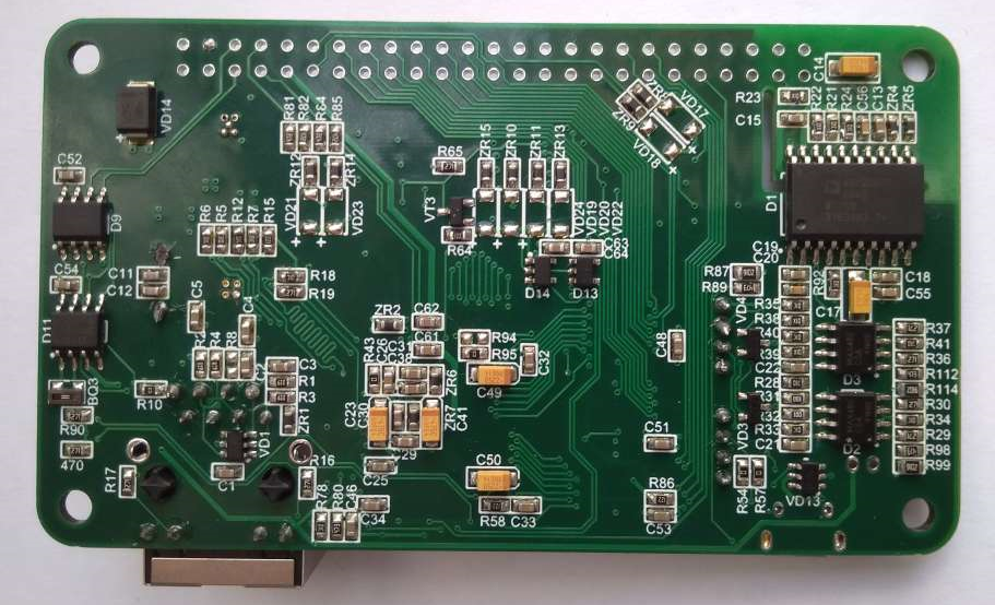
-
I have soldered the first sample of "xRoom" board.
TODO: testing and detail description of the project)) -
I didn't build this myself, but I did create the code. It's a MySensors CO2 sensor that is part of a 'privacy friendly smart home of the future' which will be launched later this year.
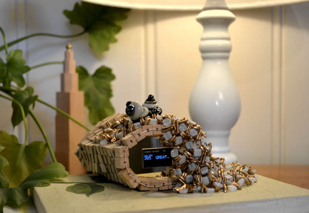
It was made by artist and jeweler Dinie Besems. All her creations feature small 'skirts' that you can lift to see the data, or cover up the screen if you have visitors and don't want them to immediately see your data.
-
Meet Janus project, a premium USB dongle by Tekka and me :sunglasses:
Dual RF gateway with external antennas.
- nrf52840 with 20dB PA + SMA connector. So it can be compatible with MySensors, and/or zigbee..
- rfm69hcw/rfm95 long range + SMA connector . module has all DIO pins routed for sw driver optimizations.
- reset button
- user button
- RGB led
- high PSRR RF/analog 700mA LDO
- usb protected
- 4layers board
- enclosure size : 52x21 (thickness 11mm). compact!
Enclosure is just a quick proto, I'll improve quality, or I would like to try online multijet service, I'm curious :)
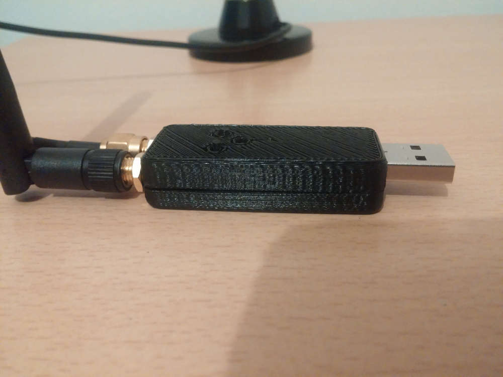
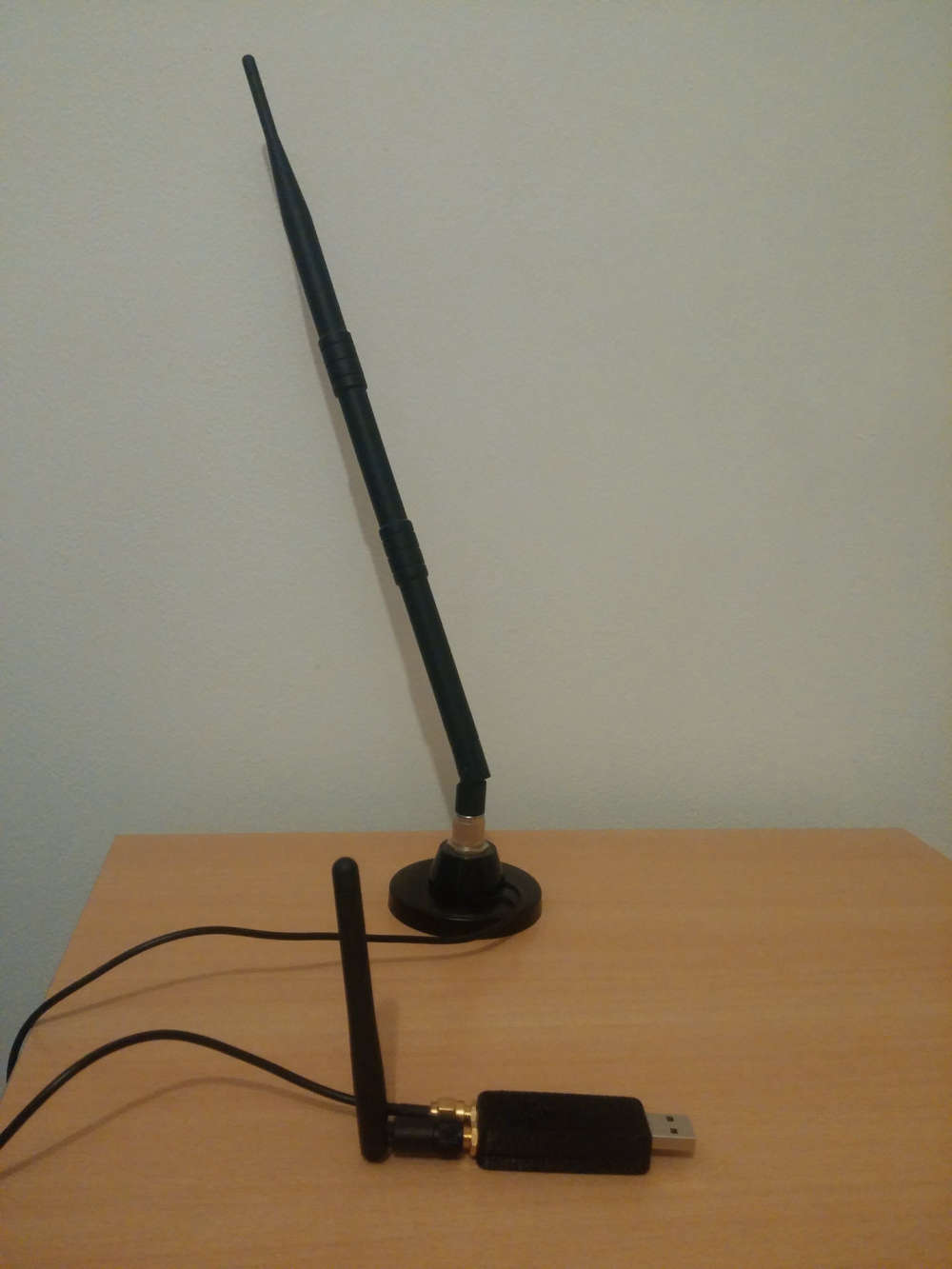
It's very recommended, for better performance, to have some distance between antennas.
So, for example, I'll use a shorter antenna (without cable) for 2.4ghz, and a "remote" antenna (with a cable) for 433/868/905Mhz, so it can be used with different kind of antennas.We choosed external antennas, because
- versatile use
- better range especially when dongle is close to lot of stuff which could affect range in case of a pcb antennas