What did you build today (Pictures) ?

-
Meet Janus project, a premium USB dongle by Tekka and me :sunglasses:
Dual RF gateway with external antennas.
- nrf52840 with 20dB PA + SMA connector. So it can be compatible with MySensors, and/or zigbee..
- rfm69hcw/rfm95 long range + SMA connector . module has all DIO pins routed for sw driver optimizations.
- reset button
- user button
- RGB led
- high PSRR RF/analog 700mA LDO
- usb protected
- 4layers board
- enclosure size : 52x21 (thickness 11mm). compact!
Enclosure is just a quick proto, I'll improve quality, or I would like to try online multijet service, I'm curious :)
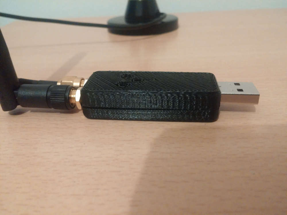
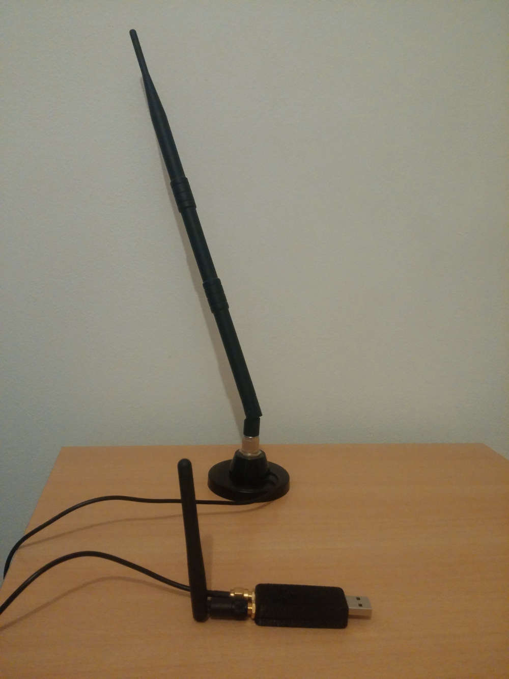
It's very recommended, for better performance, to have some distance between antennas.
So, for example, I'll use a shorter antenna (without cable) for 2.4ghz, and a "remote" antenna (with a cable) for 433/868/905Mhz, so it can be used with different kind of antennas.We choosed external antennas, because
- versatile use
- better range especially when dongle is close to lot of stuff which could affect range in case of a pcb antennas
-
thx for interests guys :)
I'm just not sure if there would be enough interest for me to produce. I've not really thought about it! It's the first board of the batch.I call it a premium dongle because
- it's 4layers. It's just a little bit more expensive than 2layers. But quality is a lot increased (better impedance, full gnd plane, better routing etc). It's also recommended by lot of rf module manufacturers for topnotch perf
- I uses the high quality BT840XE module. As you know, it's a well documented and known module, and it's CE/FCC (better, as it includes a 20dB PA).
Actually I just use a few pins on edges, and 18 pads under it..
I had the choice to use this module, or to design mine with a frontend, but for once, I decided to go "simple" for a quick debug. And the price difference vs homemade, maybe +10€, is worth it imho, time saver, and I don't mind I just need one!
Why did I make it? Because I can and would be pity to deprive myself :)
And we can have a nice and reliable dongle for the team, just in case.You're right I have others hobby projects, they're not dead.. :sweat_smile:
- just lost a bit of interest on Aeos release, I agree on this, because I prefer subghz for mysensors, and would like to keep 2.4 for others protocols.
- Halo is not dead, actually it's one my favorite. I just need to find a way to include Janus in my "serverless" project which is mostly ethernet based (I made a full webapp, that I'm porting to true native crossplatform sw, android phone+tv, windows, linux, for better experience). "serverless" meaning optional rpi/computer
Oki, I'll post others pics soon.
-
Meet Janus project, a premium USB dongle by Tekka and me :sunglasses:
Dual RF gateway with external antennas.
- nrf52840 with 20dB PA + SMA connector. So it can be compatible with MySensors, and/or zigbee..
- rfm69hcw/rfm95 long range + SMA connector . module has all DIO pins routed for sw driver optimizations.
- reset button
- user button
- RGB led
- high PSRR RF/analog 700mA LDO
- usb protected
- 4layers board
- enclosure size : 52x21 (thickness 11mm). compact!
Enclosure is just a quick proto, I'll improve quality, or I would like to try online multijet service, I'm curious :)
It's very recommended, for better performance, to have some distance between antennas.
So, for example, I'll use a shorter antenna (without cable) for 2.4ghz, and a "remote" antenna (with a cable) for 433/868/905Mhz, so it can be used with different kind of antennas.We choosed external antennas, because
- versatile use
- better range especially when dongle is close to lot of stuff which could affect range in case of a pcb antennas
-
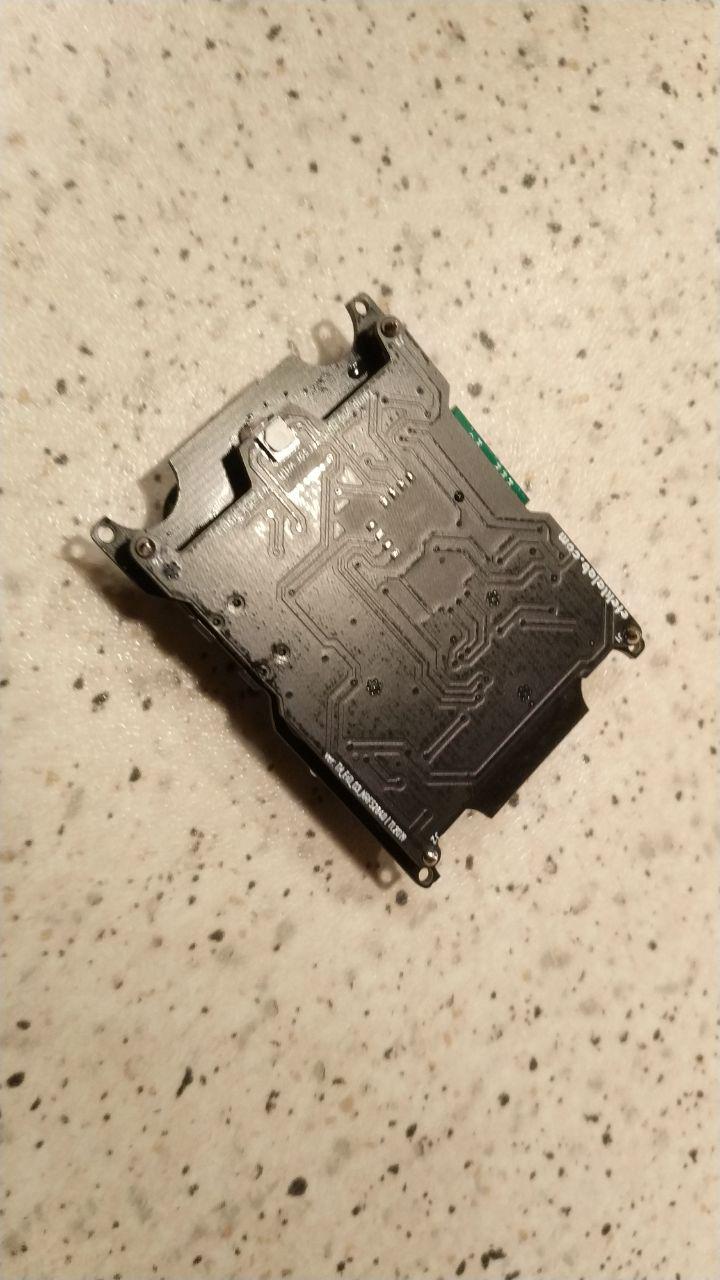
This evening I assembled another dongle (and a few other boards).
@nca78 as you asked, here is a pic during tests. Tiny dual rf dongle board, isn't it :)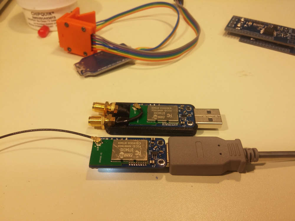
:sunglasses:
@scalz said in What did you build today (Pictures) ?:
This evening I assembled another dongle (and a few other boards).
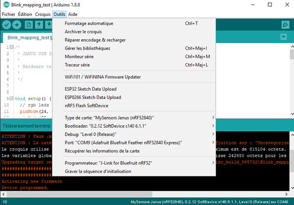
@nca78 as you asked, here is a pic during tests. Tiny dual rf dongle board, isn't itThis customization boards adafruit? I've customized the Board Sandeep Mistry.
-
@scalz said in What did you build today (Pictures) ?:
This evening I assembled another dongle (and a few other boards).
@nca78 as you asked, here is a pic during tests. Tiny dual rf dongle board, isn't itThis customization boards adafruit? I've customized the Board Sandeep Mistry.
- like I said, MySensors bridge, combo . Yes I know about resources.
Note: zigbee is out of MySensors scope (not arduino code), so for the moment some ideas and POCs will be local, not making money no ETA, still lot of WIPs and the daily job! - yes.
- like I said, MySensors bridge, combo . Yes I know about resources.
-
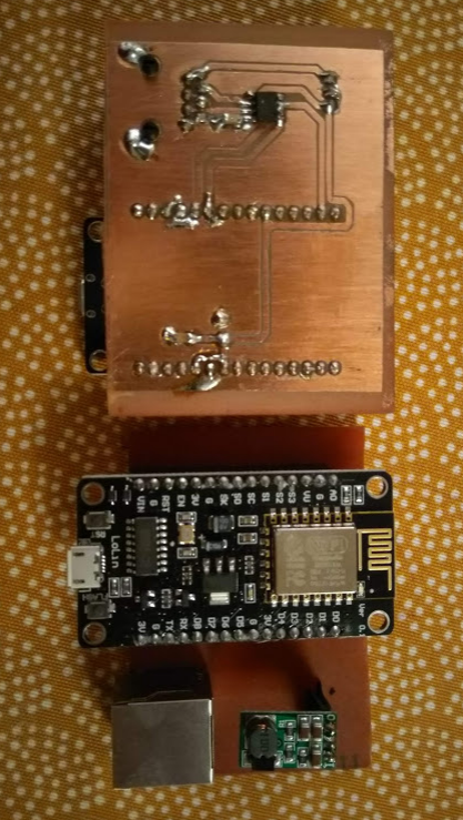
Modified a laser filament sensor (pat9125, used with Prusa mk3) to be used with an ESP32.
Maybe I will use it as a filament stuck sensor with octoprint. Or a filament meter?
-
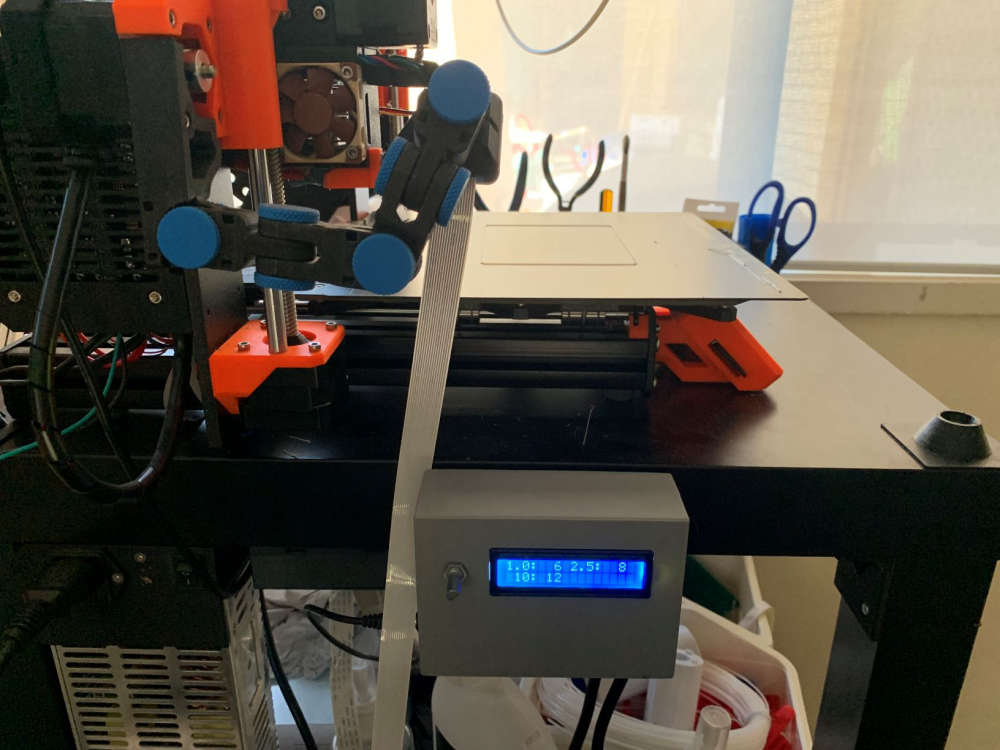
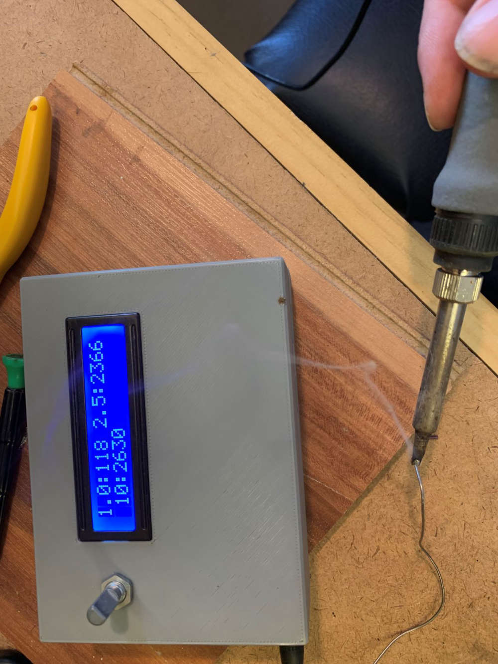
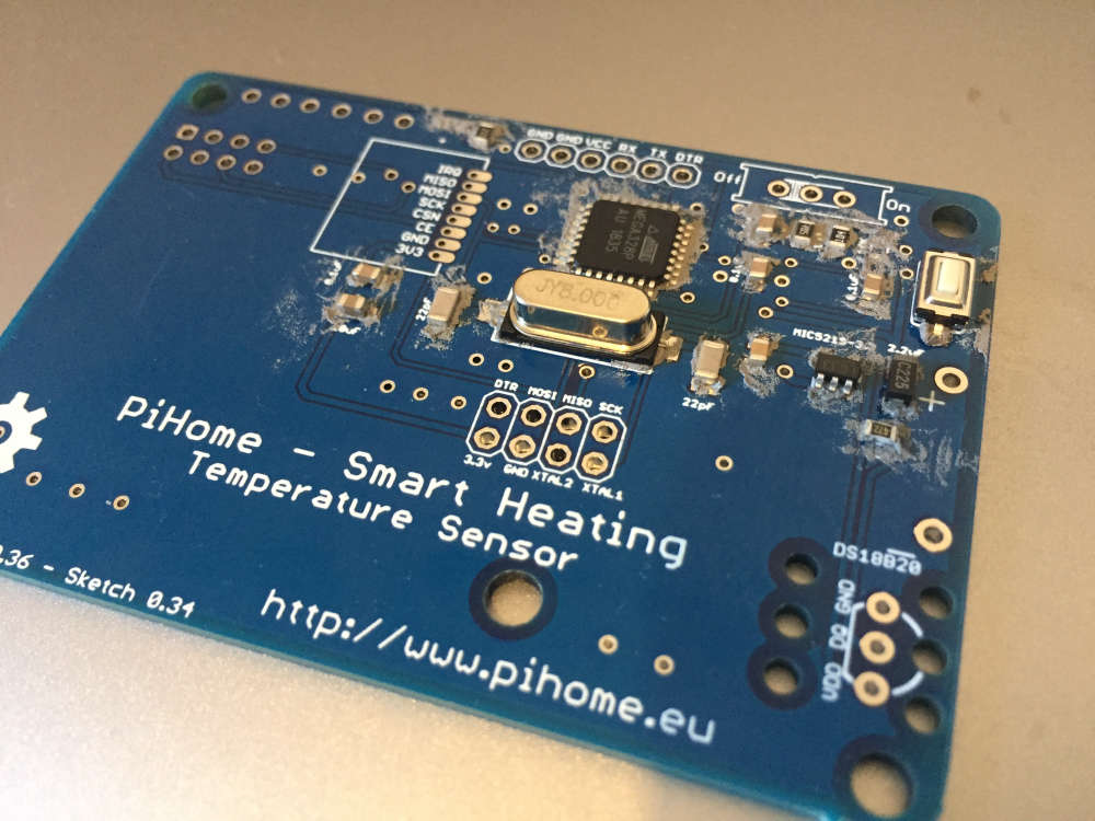
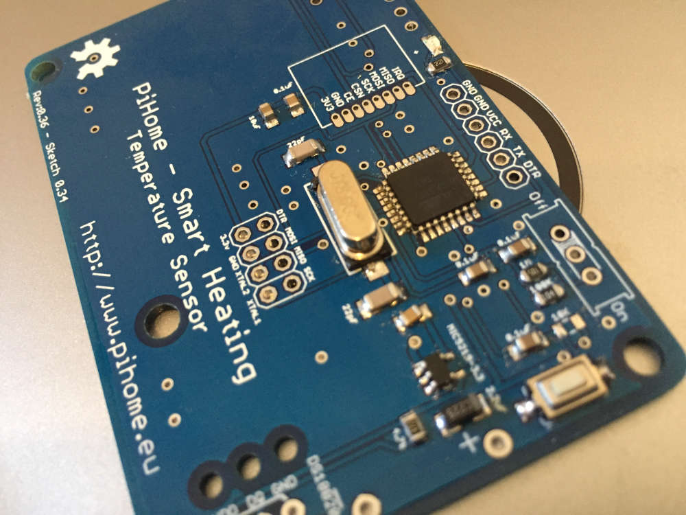
First of the winter projects done, just the programming to finish and replacement temperature chips to get (broke the legs off both DS18B20s through clumsiness).
With mains/battery backup and RTC, it will record boiler start/stop and run times as well as feed/return temperatures, and as an aside the inevitable power cuts which plague this part of the world.
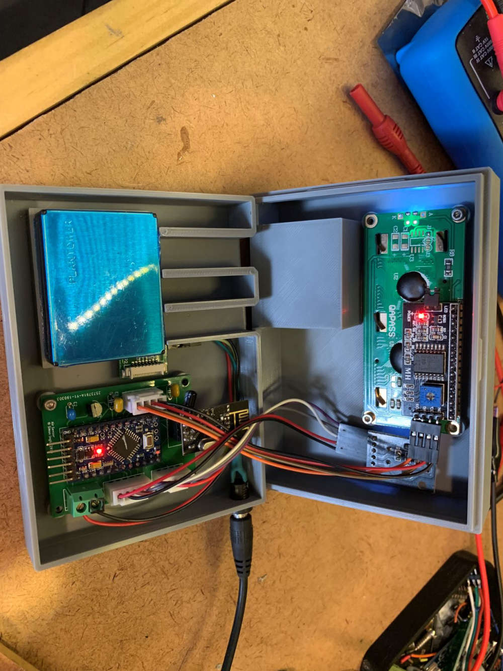
The MCU plugs into a socketed backplane hot-glued to the back of the box should removal prove necessary, but quite pleased it is sturdy and all fitted into a slim 25mm deep standard (cheap) box.
![0_1572107113418_20191026_182803[1].jpg](/assets/uploads/files/1572107121265-20191026_182803-1-resized.jpg)
-
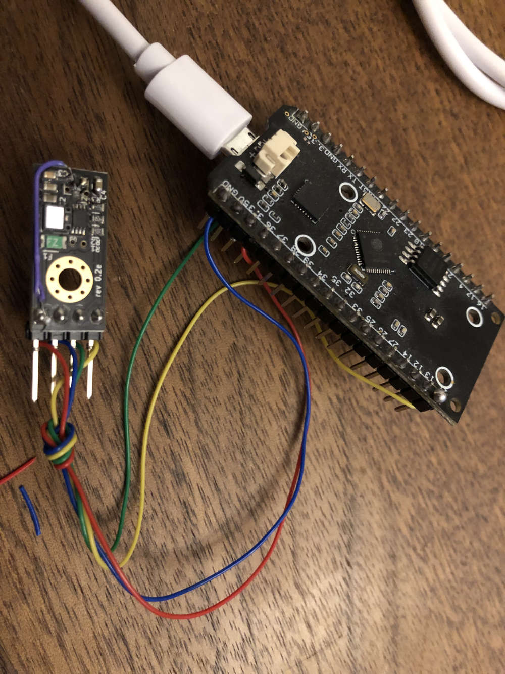
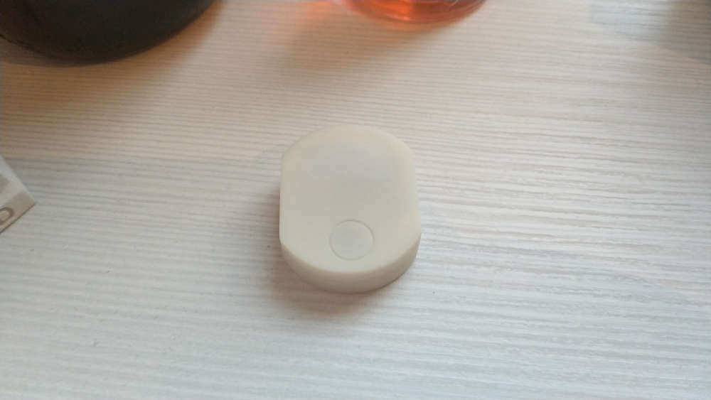
My brand new device on nRF52840. It is a light and shock(vibration) sensor.
Two sensors are used, max44009 light sensor (1 ua) and lis2dw accelerometer (1 ua).
The light sensor measures in Lux.
The shock sensor has five levels of sensitivity.
Two modes of operation: main (working) mode and command reception mode.
The sensor accepts settings: the interval of sending data from the light sensor (in minutes), sending recalculated light data from Lux to watts per meter squared(on/off), the sensitivity level of the shock sensor(5 levels, 1 to 5)
Depending on which sensors are installed on the PCB, it can be used only as a light sensor, only as a shock sensor or both.
In the near future the project will be posted on openhardware.io
video (inside view of the sensor, an example of working with a smart home, an example of setting): - https://youtu.be/I2ywIxp-RsE
-
My brand new device on nRF52840. It is a light and shock(vibration) sensor.
Two sensors are used, max44009 light sensor (1 ua) and lis2dw accelerometer (1 ua).
The light sensor measures in Lux.
The shock sensor has five levels of sensitivity.
Two modes of operation: main (working) mode and command reception mode.
The sensor accepts settings: the interval of sending data from the light sensor (in minutes), sending recalculated light data from Lux to watts per meter squared(on/off), the sensitivity level of the shock sensor(5 levels, 1 to 5)
Depending on which sensors are installed on the PCB, it can be used only as a light sensor, only as a shock sensor or both.
In the near future the project will be posted on openhardware.io
video (inside view of the sensor, an example of working with a smart home, an example of setting): - https://youtu.be/I2ywIxp-RsE
@berkseo this would also be good for monitoring when the trash cans get picked up by the garbage truck. If it has enough range that is. Of course that wouldn't apply to high rise dwellers, but for people in houses it would be a nice perk.
-
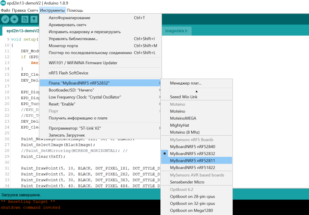
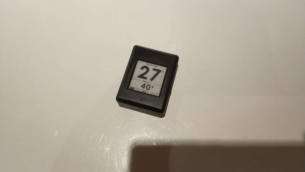
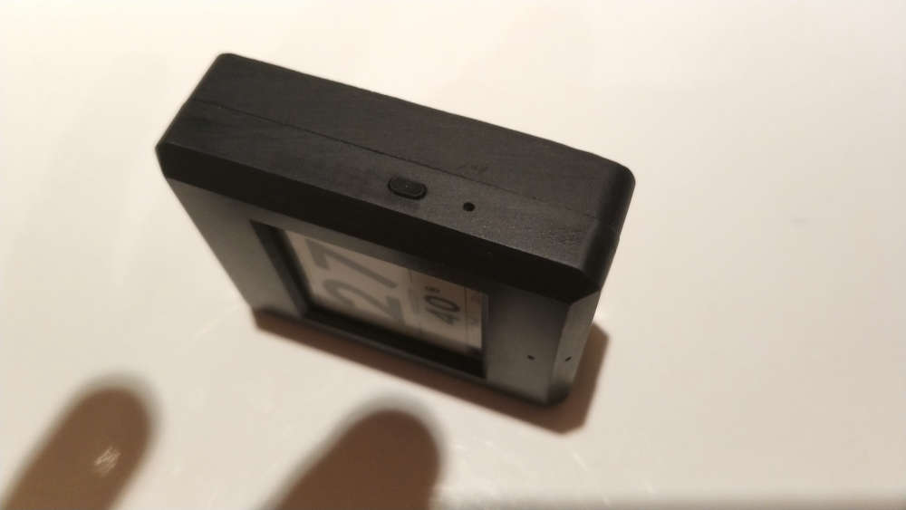
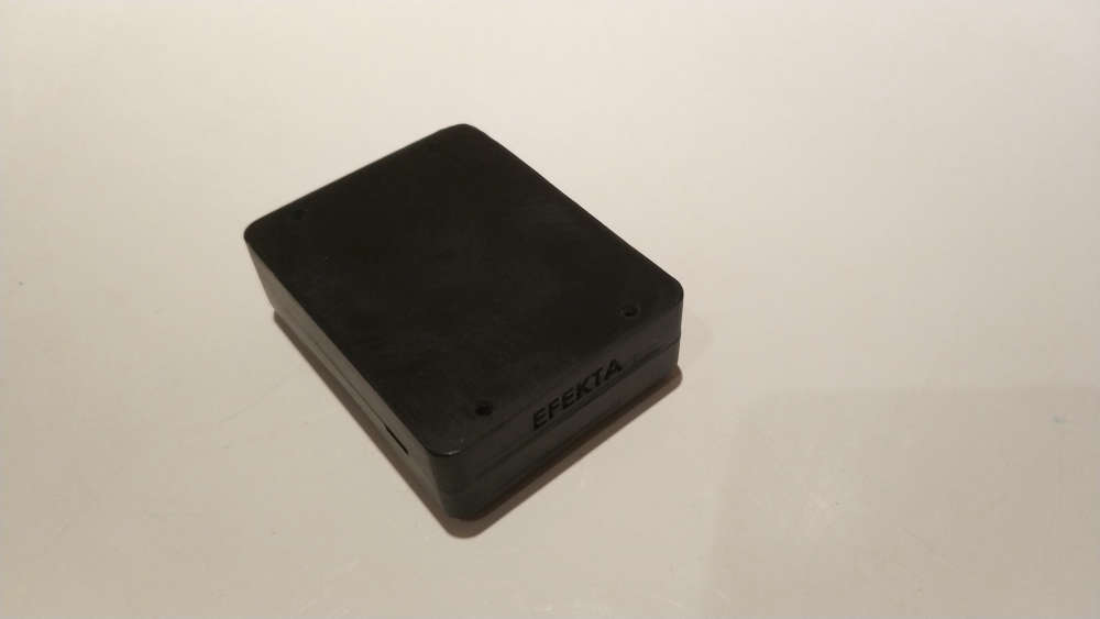
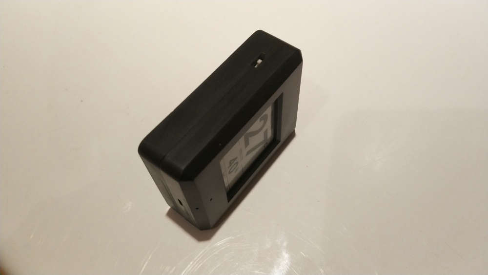
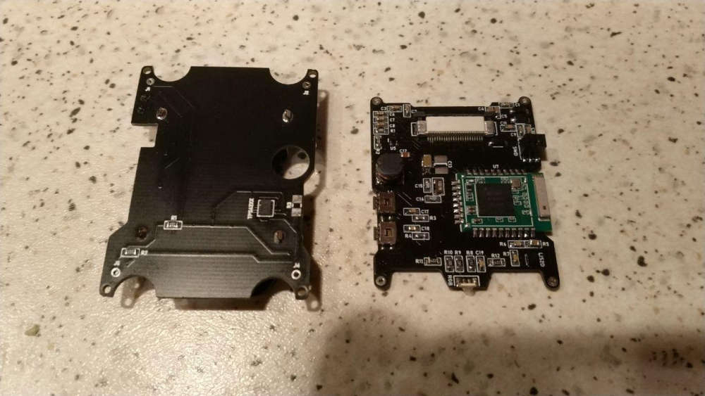
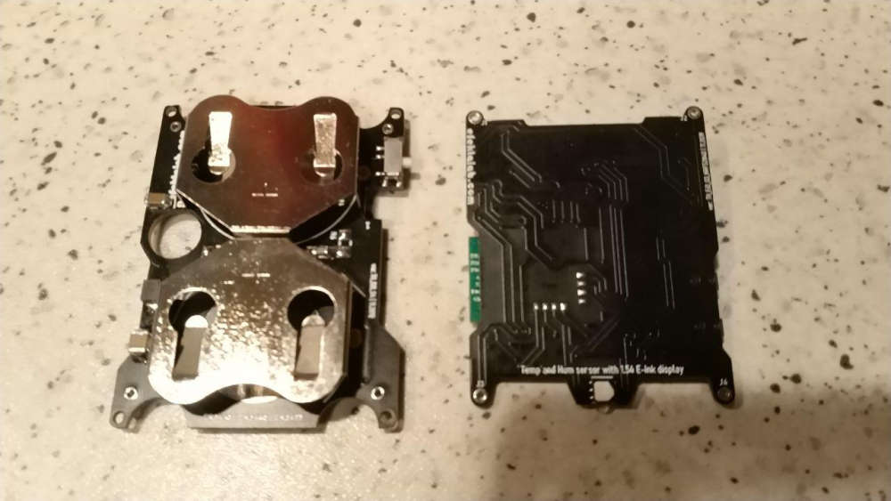
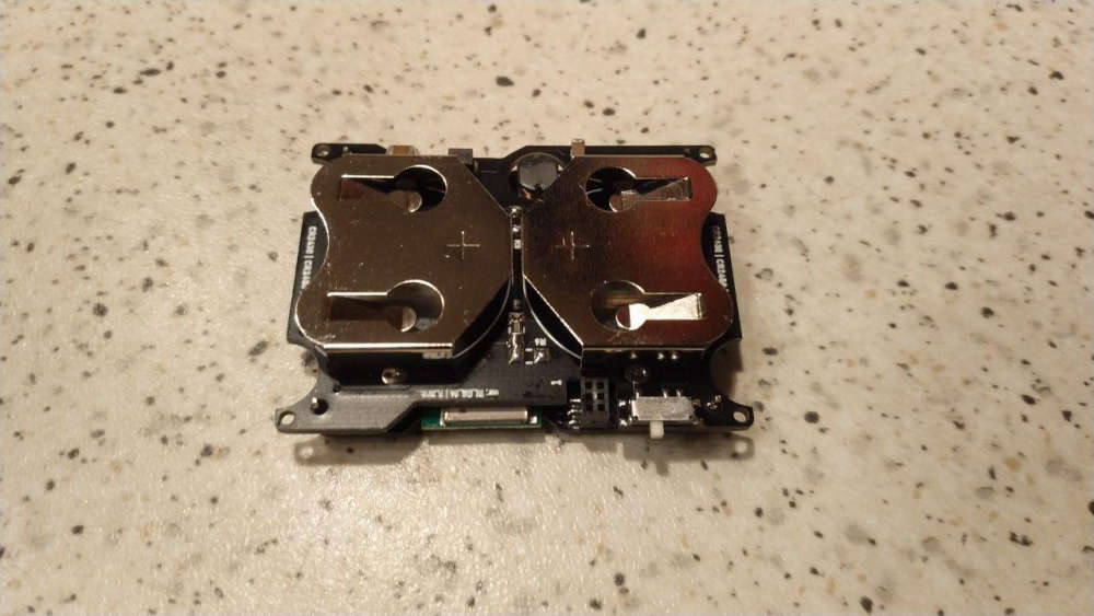
An updated version of my temperature and humidity sensor with e-ink. Now on nRF52840. Now it is not a module but a device in the case.
Replaced temperature sensor sht20 -- > > si7020
Added accelerometer.In the near future the project will be posted updated on the website openhardware.io
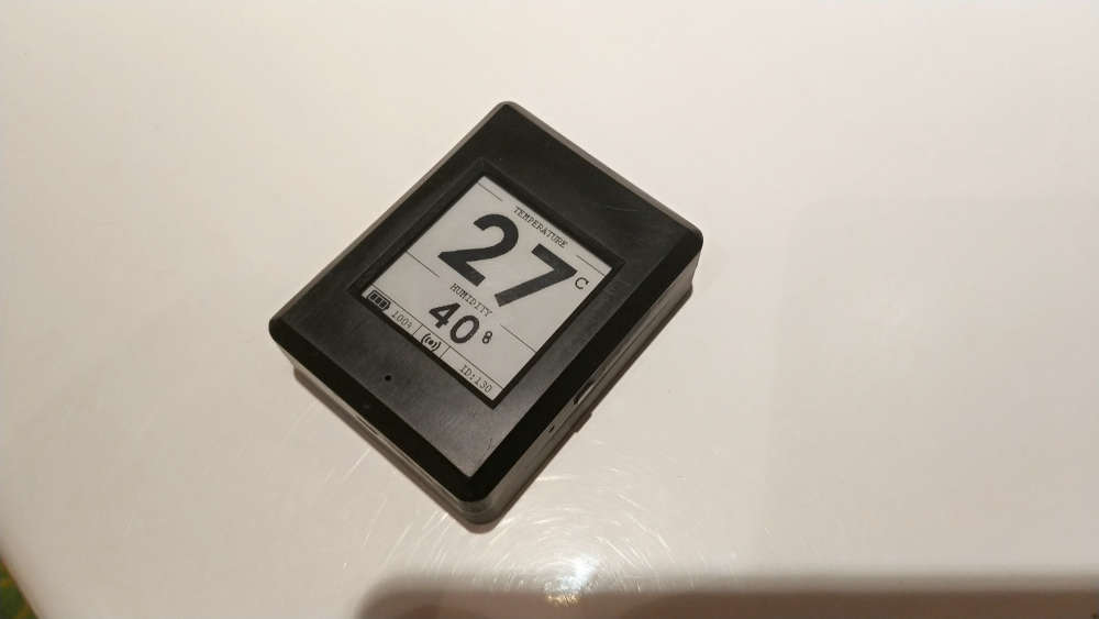
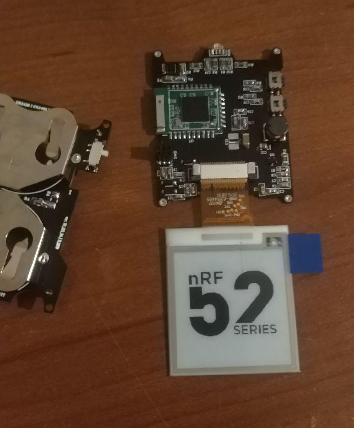
Video: https://youtu.be/T66y83lF-xg
-
-
Amazing! 😃
The case is 3d printable?
@franz-unix
This is made on SLA printer, but should normally print on FDM -
An updated version of my temperature and humidity sensor with e-ink. Now on nRF52840. Now it is not a module but a device in the case.
Replaced temperature sensor sht20 -- > > si7020
Added accelerometer.In the near future the project will be posted updated on the website openhardware.io
Video: https://youtu.be/T66y83lF-xg
@berkseo I'm quite interested in a schematic view showing how the epaper gets wired up, because priced just by itself epaper seems like an affordable solution.
or
On the other hand, if one has to rely on adafruit or similar for an epaper breakout board to make use of it, the effective price jumps by around 5-6x or so.
-
https://github.com/dkjonas/Wavin-AHC-9000-mqtt
iron and toner transfer, then etched and soldered and finally acrylic spray on cobber so it won't corrode