What did you build today (Pictures) ?

-
My wife said "I do not want to see "those things""...
Challenge accepted!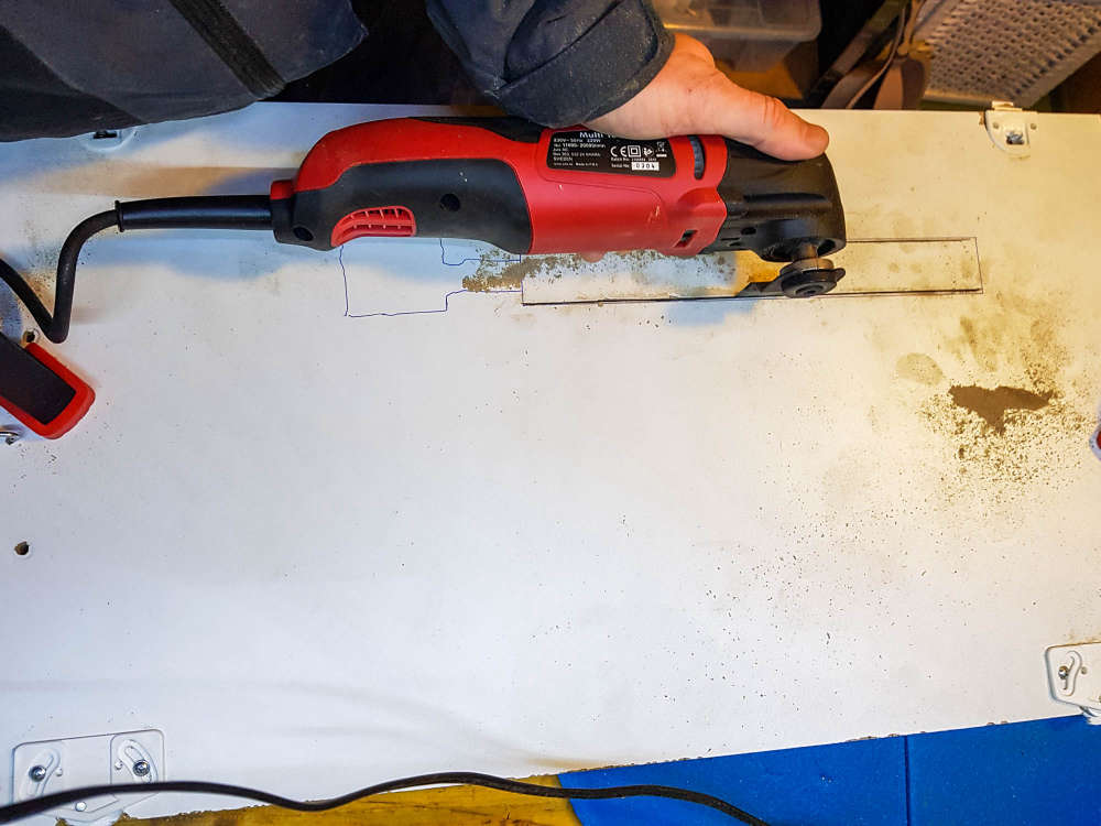
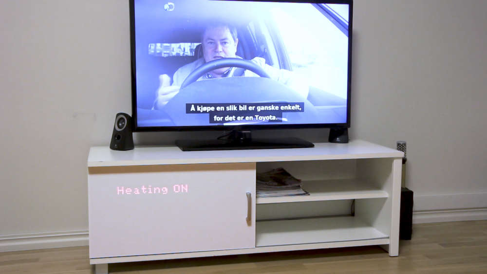
(see the gif in action here https://ibb.co/BCbS2Dc )
-
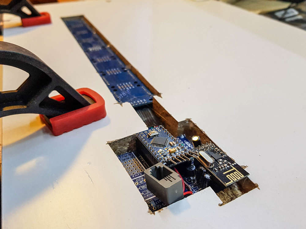
@dakipro thank you that's what I planned to do but wasn't sure it would be visible through the plastic layer.
Coupled with capacitive sensors it could give awesome results !@nca78 I used white decorative self adhesive wallpaper, so not sure which plastic you are planing to use, but you can easily test that before mounting I think. If you go for paper/foil, put some one-peace plastic in front of the displays as they (mine) are not perfectly soldered in line, so they are noticeable sa foil will glue to them. Not a big deal for me, but would love "the perfection". But yeah, plastic or some harder material would work awesome I think.
All in all, not difficult project and a very high wow-factor/time-spent value (and waf)
-
@nca78 I used white decorative self adhesive wallpaper, so not sure which plastic you are planing to use, but you can easily test that before mounting I think. If you go for paper/foil, put some one-peace plastic in front of the displays as they (mine) are not perfectly soldered in line, so they are noticeable sa foil will glue to them. Not a big deal for me, but would love "the perfection". But yeah, plastic or some harder material would work awesome I think.
All in all, not difficult project and a very high wow-factor/time-spent value (and waf)
-
-
Looks great. I'm still happy when I get an 0805 down well. Guess I have to keep practicing.
@nagelc said in What did you build today (Pictures) ?:
Looks great. I'm still happy when I get an 0805 down well. Guess I have to keep practicing.
Try solder paste applied with a thin needle, and a hot air gun at minimum speed (so components don't fly away). Then it's really easy to do SMD :)
-
@nagelc said in What did you build today (Pictures) ?:
Looks great. I'm still happy when I get an 0805 down well. Guess I have to keep practicing.
Try solder paste applied with a thin needle, and a hot air gun at minimum speed (so components don't fly away). Then it's really easy to do SMD :)
@nca78 there many other aspects. I’m using a low temp melting solder paste. I have been using only a top quality (no AliExpress) one from Chipquick. It has to be stored property in the fridge.
Using stencil may help. I’m not using it and have to doze the paste very precisely which is a challenge. This is why my soldering is not 100% consistent, but it works. With 0402 components it is not easy - the pad size is very small.
However, I must admit, 0402 are far too small. In the process, unless your space / lab is very well organised many components are lost. And a good magnifying glass / microscope is a must too. In the future, i’ll try to stick to 0805 or larger - these are a bit larger and more visible.
All in all, this is not as difficult as many people may think. With a little bit of practice, this can be done.
-
Looks great. I'm still happy when I get an 0805 down well. Guess I have to keep practicing.
-
Try this one.
The smallest board I have ever assembled using just a hot fan. A solar battery charger based on BQ25504 from a solar panel. Almost all components are 0402. Far too small for my liking, but can go under the solar panel.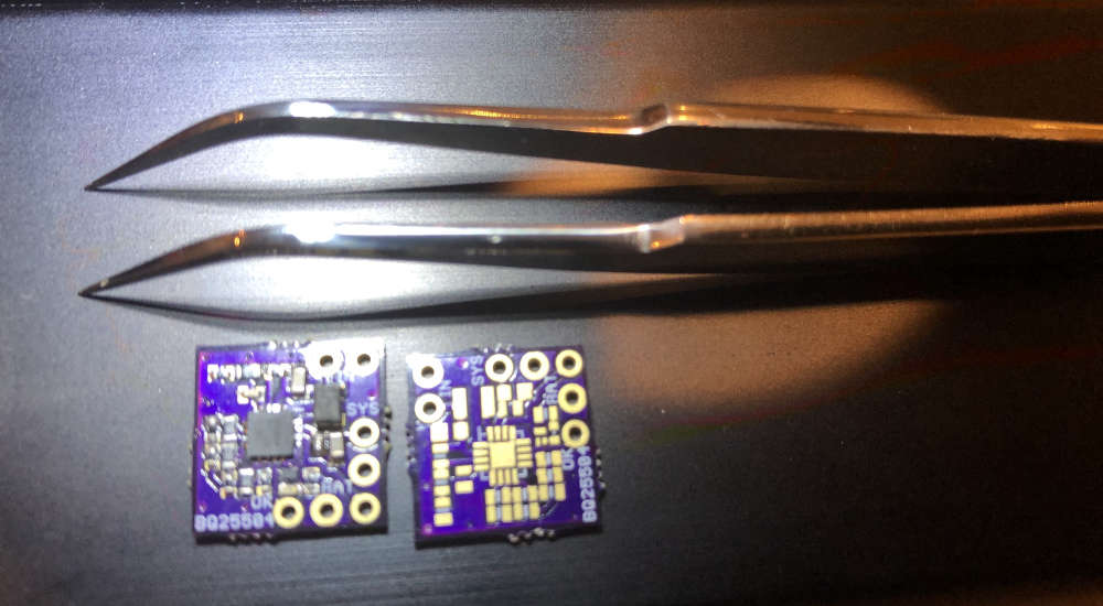
-
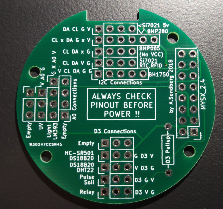
Today i recieved my new mini-easy-pcb i posted some info about 3 months ago. This with a breakoutboard-daugher board for all "common" sensors in the MySensors shop. I want to create a small motherboard which can be powered using a battery but also can use the battery for UPS/backup if powered from another daugherboard. The motherboard should be standard and then I would be able to add 1-2 daugherboards to specify the node.
The breakoutboard is just for test, but can be used by newbies offcourse.
My wish is to create the ultimate security sensor running on 12v but with a battery backup. It should include motion, temp, smoke and light.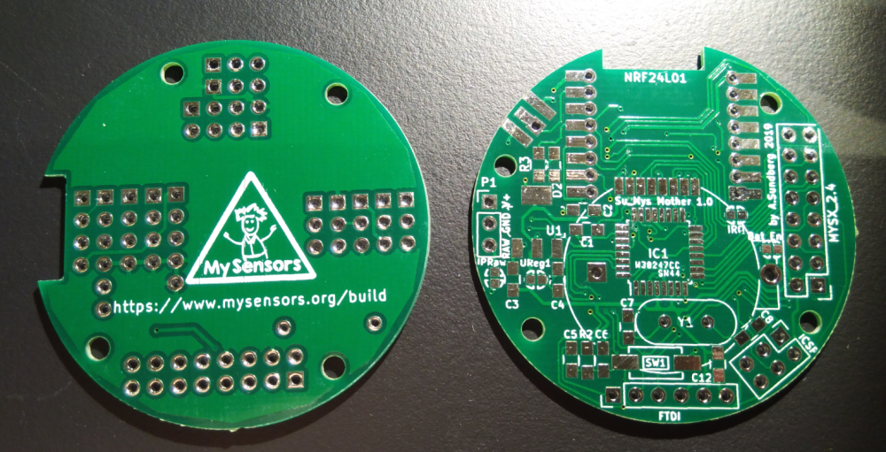
Il will get back in another 3 months when tested ;)
-
Today i recieved my new mini-easy-pcb i posted some info about 3 months ago. This with a breakoutboard-daugher board for all "common" sensors in the MySensors shop. I want to create a small motherboard which can be powered using a battery but also can use the battery for UPS/backup if powered from another daugherboard. The motherboard should be standard and then I would be able to add 1-2 daugherboards to specify the node.
The breakoutboard is just for test, but can be used by newbies offcourse.
My wish is to create the ultimate security sensor running on 12v but with a battery backup. It should include motion, temp, smoke and light.Il will get back in another 3 months when tested ;)
@sundberg84 Nice job.
-
@nagelc said in What did you build today (Pictures) ?:
Looks great. I'm still happy when I get an 0805 down well. Guess I have to keep practicing.
Try solder paste applied with a thin needle, and a hot air gun at minimum speed (so components don't fly away). Then it's really easy to do SMD :)
-
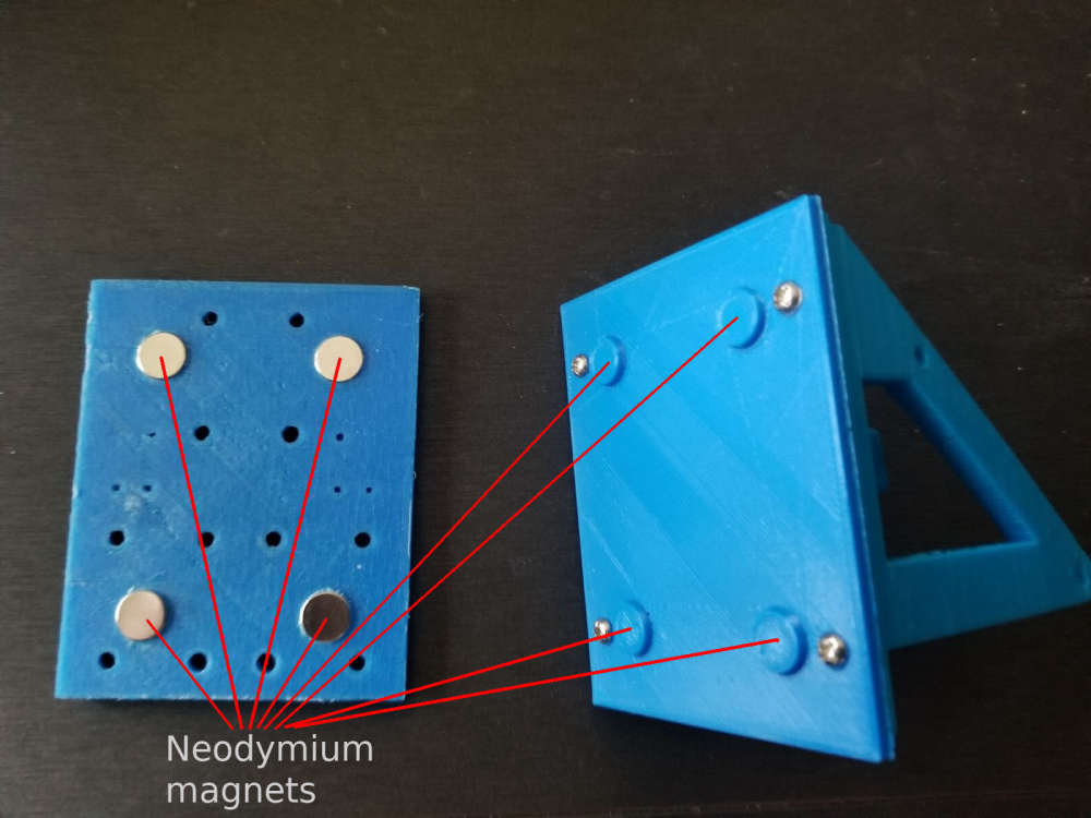
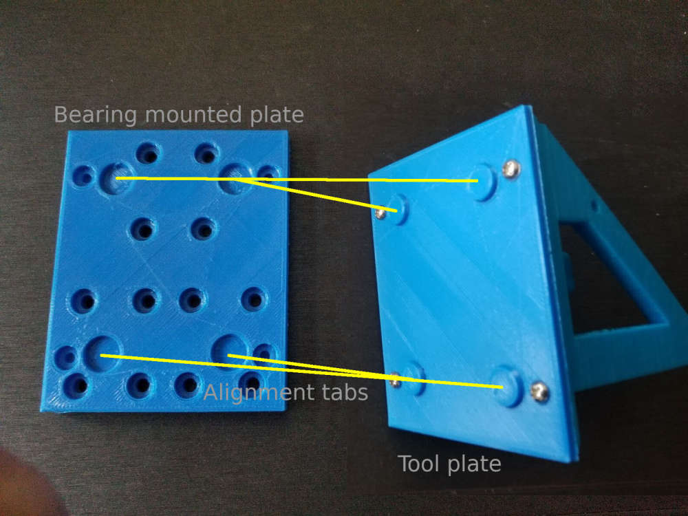
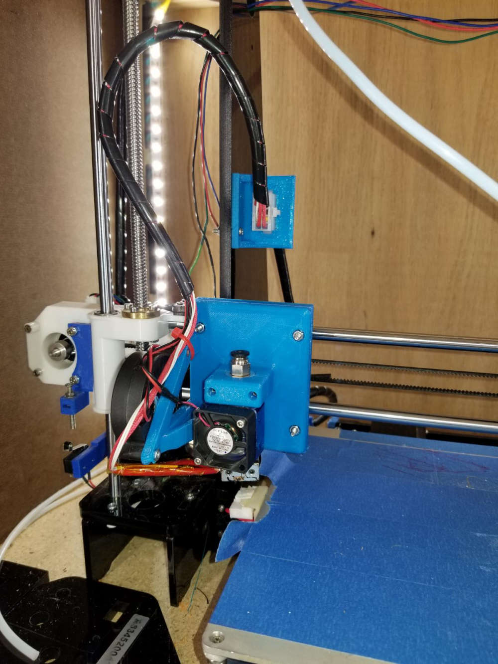
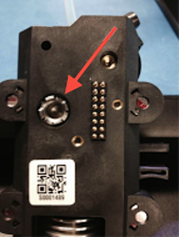
So for some time now I have been working on a conversion to my 3D printer to allow me to change between different tool heads easily, thus increasing the versatility of the machine. To jump right in and give a little background on the mod, I have a plate that mounts to my X carriage that has 4 10mm neodymium magnets in it. These magnets hold the tool in place that will be used which also has 4 magnets in it's mounting plate.
The first tool that I did was my 3D printer head. I obviously did that one first because I would need that to make future parts and tool heads to expand the machine. Here is my 3D printer head mounted to the working assembly.
Another tool head that I made for this is my simple pen plotter tool for drawing.
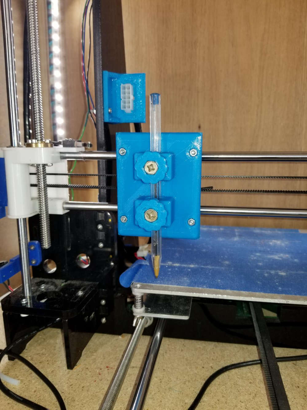
Here is a sample of something I did with the pen plotter using fine point sharpie markers. The left is the original image, and the right was done with the plotter.

The most recent tool head that I did was my laser engraver tool. This tool is the main reason for this post. This is the 6 watt laser module mounted to the carriage.
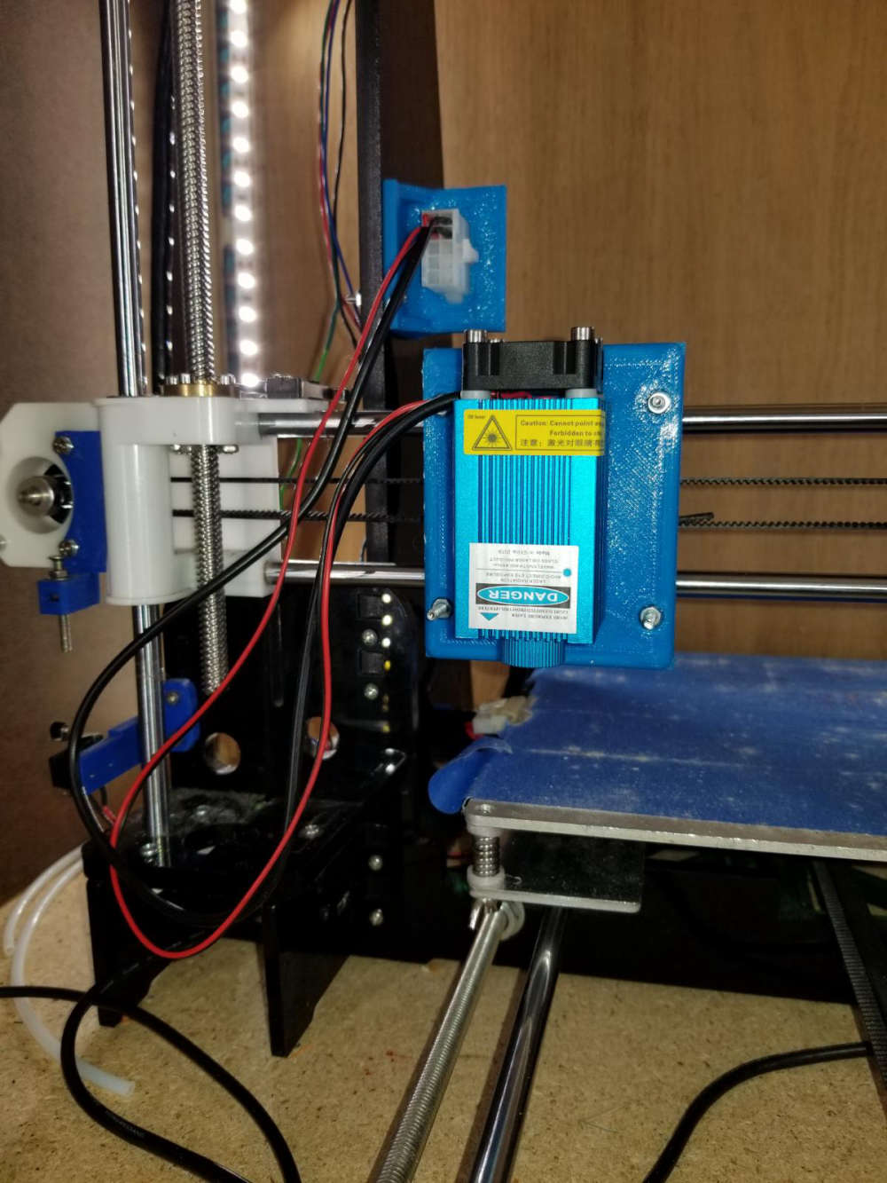
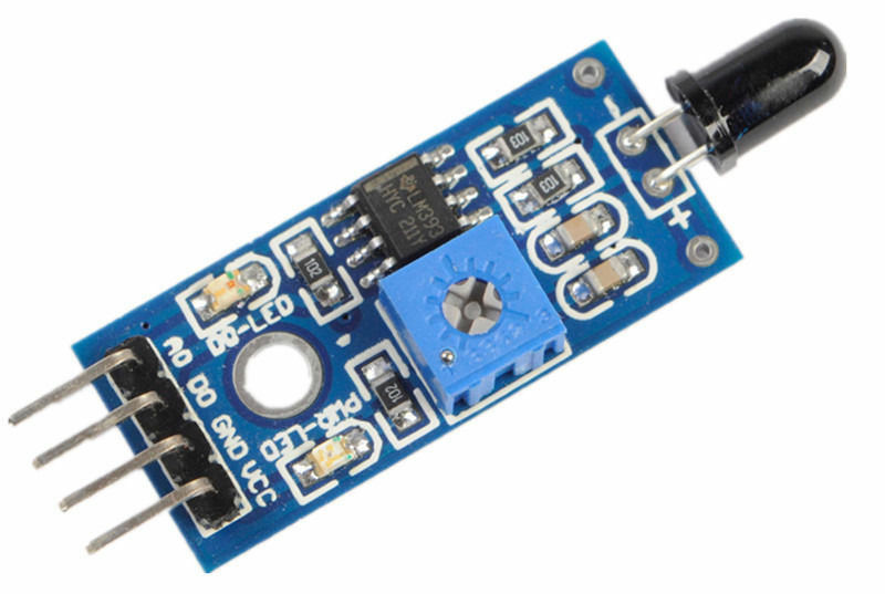
So what I am looking to do with this on the MySensors end of things is to build some sort of flame sensor that can monitor the engraving operation to indicate a small fire and take some sort of action, and also report it to my vera controller. Exactly what action I would have it take I have not figured out yet. If anyone has suggestions I'm all ears. I was thinking of something that could easily extinguish the small flame. As for the flame sensor, I know they make these small flame sensor modules, but I don't know how reliable they are, ore even how they work.
For anyone interested, here is a sample engraving on a piece of thin plywood. The left image is the original. The center is at a low resolution, and the right one was at a high resolution.

One other thing that I want to test with this is I've seen people that make circuit boards with these. They spray a layer or two of paint on their blank copper clad and then laser etch their pattern on the painted surface. Then they run it through their ferric chloride or other etching solution. Finally, sand off the layer of paint.Any suggestions or help people can give is greatly appreciated. Thanks for viewing.
-
@mfalkvidd Not a bad idea. I could get a CO2 canister with a solenoid valve and hook it to a hose that would blow CO2 directly onto the flame to put it out. Since my 3D printer is in an enclosure, it should contain the CO2 helping further extinguish the flame.
-
Cool setup, is the adapter system stable enough for the different tools? Mainly the extruder for the 3d printing?
@tbowmo With the 4 recessed indents on the plate, it centers the tool being mounted pretty good. I have printed a number of things with it since the upgrade and haven't had any issues with it yet. The Makerbot Replicator series of printers use a similar way of attaching their Smart Extruder heads with the 4 magnets in the corners.
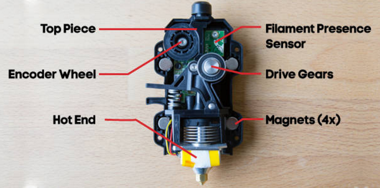
One difference between the Makerbot extruders and my setup is that the Makerbots put their extruder stepper behind the hot end assembly and that mates to the motor with a castle nut type assembly.
My setup uses a Bowden extruder setup that is mounted at the top of my enclosure.
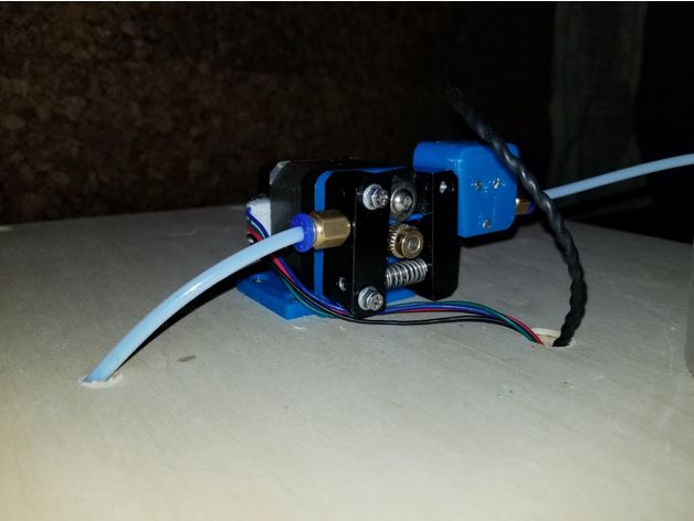
With no stepper on my hot end, that takes the majority of the weight off of the carriage. This is one of the first tests of the 3D printer head.
https://www.youtube.com/watch?v=PGpMOA4mhyI

Hello! It looks like you're interested in this conversation, but you don't have an account yet.
Getting fed up of having to scroll through the same posts each visit? When you register for an account, you'll always come back to exactly where you were before, and choose to be notified of new replies (either via email, or push notification). You'll also be able to save bookmarks and upvote posts to show your appreciation to other community members.
With your input, this post could be even better 💗
Register Login