Sketch for Lightning Sensor
-
Hi all,
Well I was finally home when a thunderstorm rolled through and I was able to test the sensor and the sketch. Even though the sensor appeared to be working at 3.3V, I had to change it to 5V to get it to work properly with the USB powered Nano I have it connected to. I modified the sketch slightly (updated in my earlier post) to no longer send data when disturbers or unknown interrupt sources were detected. It's working great now and just need to put it into a case. I may use a different Arduino as well.
Cheers
Al -
Sweet. Would you want to create a pull request when you're ready with this example (including AS3935 library)?
-
Is it possible to detect the distance to the lightningstrike?
I was thinking to get some sort of detector to notify me if there is ligning registered X km away from my home. -
Is it possible to detect the distance to the lightningstrike?
I was thinking to get some sort of detector to notify me if there is ligning registered X km away from my home.You would need a sound detector for the thunder. Time (in milliseconds) between lightning and thunder times 0.34[m].
Same as you would do it with your own sensors (eyes and ears) :-)
BR,
Boozz
-
Is it possible to detect the distance to the lightningstrike?
I was thinking to get some sort of detector to notify me if there is ligning registered X km away from my home.@Tore-André-Rosander Yes, the sensor can detect the distance. See the details of the sensor here: http://playingwithfusion.com/productview.php?pdid=22&catid=1001. Although I'm starting to believe that it's actually a lightning repeller rather than a lightning sensor as we've had very little lightning in our area after I installed it :laughing:
Cheers
Al -
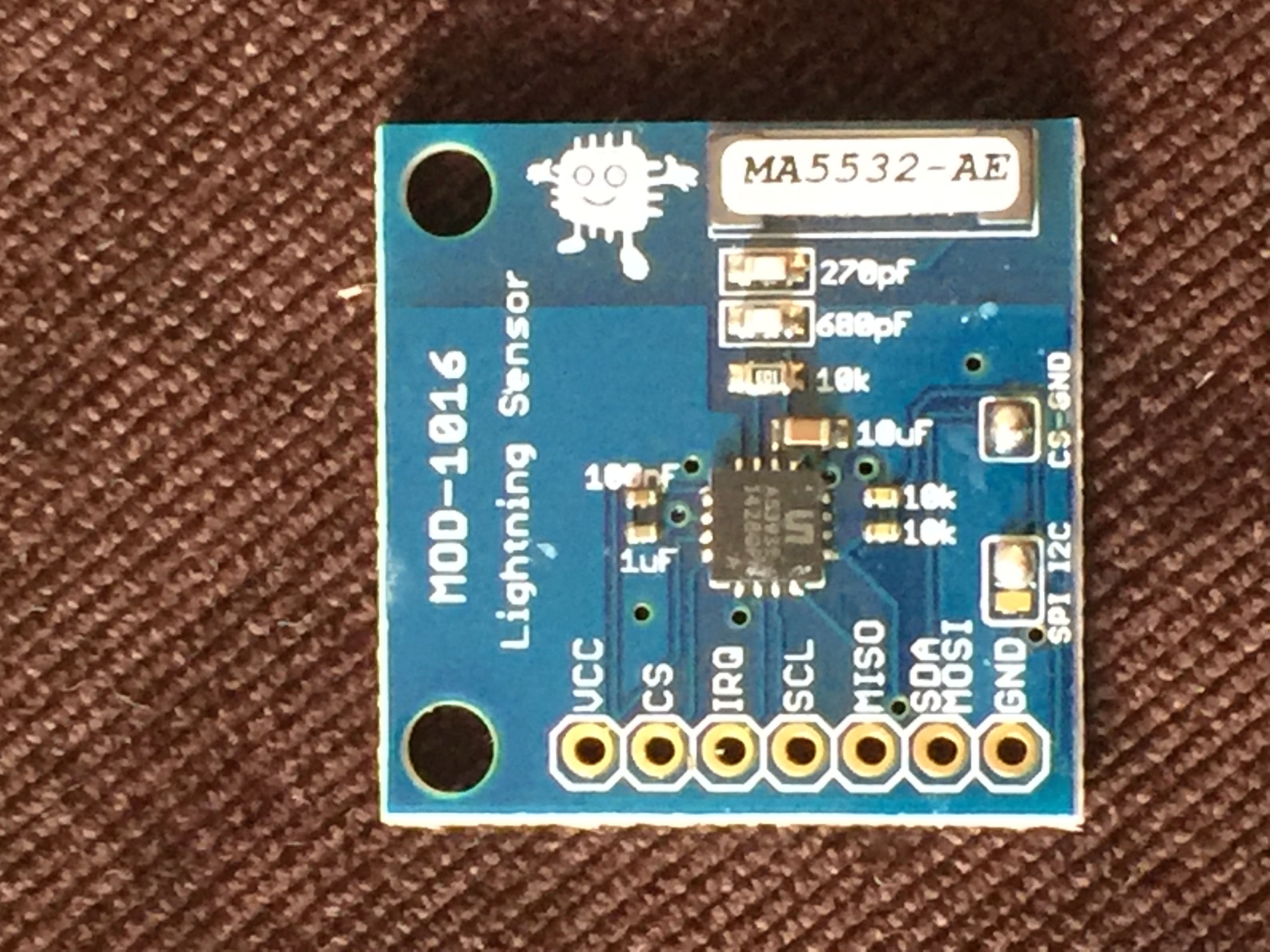
I found a similar sensor in the UK and added this to the list of my to be sensors for the weatherstation. Can I use it inside or it has to be placed outside to have a direct vision?
http://www.embeddedadventures.com/as3935_lightning_sensor_module_mod-1016.html
-
I found a similar sensor in the UK and added this to the list of my to be sensors for the weatherstation. Can I use it inside or it has to be placed outside to have a direct vision?
http://www.embeddedadventures.com/as3935_lightning_sensor_module_mod-1016.html
-
@Sparkman I suppose your wiring diagram above is correct? I noted that the sensor is not working with 3.3V. Did you manage to find what the problem was? Looking at the datasheet http://www.embeddedadventures.com/datasheets/MOD-1016_hw_v8_doc_v4.pdf I can see what the module can operate down to 2.4V
I am going to receive the sensor in a few days and test it.
As I have a different module manufacturer, I may need to change the sketch as it uses a different library. This is unmodified example sketch:
*/

// AS3935 MOD-1016 Lightning Sensor Arduino test sketch
// Written originally by Embedded Adventures


#include <Wire.h>
#include <AS3935.h>

#define IRQ_pin 2

volatile bool detected = false;

void setup() {
  Serial.begin(115200);
  while (!Serial) {}
  Serial.println("Welcome to the MOD-1016 (AS3935) Lightning Sensor test sketch!");
  Serial.println("Embedded Adventures (www.embeddedadventures.com)\n");

  Wire.begin();
  mod1016.init(IRQ_pin);

  //Tune Caps, Set AFE, Set Noise Floor
  //autoTuneCaps(IRQ_pin);

  mod1016.setTuneCaps(7);
  mod1016.setOutdoors();
  mod1016.setNoiseFloor(5);


  Serial.println("TUNE\tIN/OUT\tNOISEFLOOR");
  Serial.print(mod1016.getTuneCaps(), HEX);
  Serial.print("\t");
  Serial.print(mod1016.getAFE(), BIN);
  Serial.print("\t");
  Serial.println(mod1016.getNoiseFloor(), HEX);
  Serial.print("\n");

  pinMode(IRQ_pin, INPUT);
  attachInterrupt(digitalPinToInterrupt(IRQ_pin), alert, RISING);
  Serial.println("after interrupt");
}

void loop() {
  if (detected) {
    translateIRQ(mod1016.getIRQ());
    detected = false;
  }
}

void alert() {
  detected = true;
}

void translateIRQ(uns8 irq) {
  switch(irq) {
      case 1:
        Serial.println("NOISE DETECTED");
        break;
      case 4:
        Serial.println("DISTURBER DETECTED");
        break;
      case 8:
        Serial.println("LIGHTNING DETECTED");
        printDistance();
        break;
    }
}

void printDistance() {
  int distance = mod1016.calculateDistance();
  if (distance == -1)
    Serial.println("Lightning out of range");
  else if (distance == 1)
    Serial.println("Distance not in table");
  else if (distance == 0)
    Serial.println("Lightning overhead");
  else {
    Serial.print("Lightning ~");
    Serial.print(distance);
    Serial.println("km away\n");
  }
}
This is SPI sketch, I'd like to use I2C connection. Generally, the procedure is as follows:
Wait a few milliseconds for the system to stabilise
Set the tune capacitor to the value indicated on the packaging, by setting the
TUNE_CAP bits of register 8
Wait 2 milliseconds
Callibrate RCO by:
o Sending a calibrate RCO direct command (set memory location 0x3d to the
value 0x96)
o Set Register 0x08, bit 5 to 1
o Wait 2 milliseconds
o Set Register 0x08, bit 5 to 0
The factory calibrating tuning cap value will be fine for general use. When you have a
MOD-1016 in an enclosure or close to other electronics it is worth calibrating the tuning
cap again. -
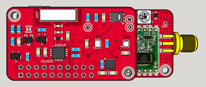
can't wait to test this one too ;) i have pcbs for a weather shield (with bme280, veml6070 etc. ) and i have this sensor on it too (https://forum.mysensors.org/uploads/files/1459631385870-stacked.jpg). But not assembled yet, was busy, i hope asap.. i plan to use it with 3v and i2c. @alexsh1 There are libs for i2c if you want :)
Thx @Sparkman for your work on it ;)
-
I'm running my sketch with I2C now, rather than SPI. I found the sensor would lock up occassionally, so recently converted it and am still testing it. I have mine running at 5v now as well instead of 3.3v, but it works fine with either.
I'll post an updated sketch (and wiring diagram) soon. I based both the spi and i2c sketches on the examples found here: http://playingwithfusion.com/productview.php?pdid=22&catid=1001.
Cheers
Al -
Absolutely delighted with the module I have received today by post. The weather is sh@t tonight (lightning, rain etc.) which means that I can test it:
Welcome to the MOD-1016 (AS3935) Lightning Sensor test sketch!
TUNE	IN/OUT	NOISEFLOOR
6	10010	5

after interrupt
DISTURBER DETECTED
DISTURBER DETECTED
DISTURBER DETECTED
DISTURBER DETECTED
DISTURBER DETECTED
LIGHTNING DETECTED
Lightning ~27km away

DISTURBER DETECTED
DISTURBER DETECTED
LIGHTNING DETECTED
Lightning ~17km away

DISTURBER DETECTED
LIGHTNING DETECTED
Lightning ~10km away
I calibrated the sensor and put a reasonable "noise floor". Now I have to convert it into MySensors and hook up to the ceech board outside.
@Sparkman I have my sensor running at 3.3V
-
@alexsh1 It looks to be a different breakout board, but for the same chip. So I would expect them to work basically the same.
Cheers
Al@Sparkman it is a different board made (or designed) by a UK company.
We are having a real British summer over here :-)))
LIGHTNING DETECTED Lightning ~20km away LIGHTNING DETECTED Lightning ~20km away LIGHTNING DETECTED Lightning ~6km away LIGHTNING DETECTED Lightning ~6km away LIGHTNING DETECTED Lightning ~6km away LIGHTNING DETECTED Lightning ~6km away LIGHTNING DETECTED Lightning ~6km away LIGHTNING DETECTED Lightning ~5km away -
@Sparkman it is a different board made (or designed) by a UK company.
We are having a real British summer over here :-)))
LIGHTNING DETECTED Lightning ~20km away LIGHTNING DETECTED Lightning ~20km away LIGHTNING DETECTED Lightning ~6km away LIGHTNING DETECTED Lightning ~6km away LIGHTNING DETECTED Lightning ~6km away LIGHTNING DETECTED Lightning ~6km away LIGHTNING DETECTED Lightning ~6km away LIGHTNING DETECTED Lightning ~5km away -
@alexsh1
There doesn't appear to be audio input to this board, nor a microphone on the board. So, how does it estimate the distance to the lightening?@NeverDie All these breakout boards are based on this chip: http://ams.com/eng/Products/Wireless-Connectivity/Wireless-Sensor-Connectivity/AS3935. They use a proprietary method to figure out distance and is not based on sound.
Cheers
Al -
@NeverDie All these breakout boards are based on this chip: http://ams.com/eng/Products/Wireless-Connectivity/Wireless-Sensor-Connectivity/AS3935. They use a proprietary method to figure out distance and is not based on sound.
Cheers
Al@Sparkman said:
@NeverDie All these breakout boards are based on this chip: http://ams.com/eng/Products/Wireless-Connectivity/Wireless-Sensor-Connectivity/AS3935. They use a proprietary method to figure out distance and is not based on sound.
Cheers
AlAny impression yet as to how accurate its distance estimates are?