GUIDE - NRF5 / NRF51 / NRF52 for beginners
-
Yes, I understood what you meant. I will only do the "Export compiled Binary" from the IDE, and leave the drivers as J-Link commander or nrfGo Studio wants them.
In: https://www.openhardware.io/view/376/MySensors-NRF5-Platform it says:
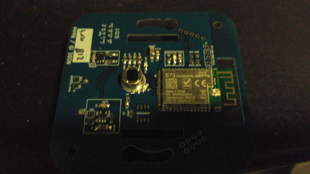
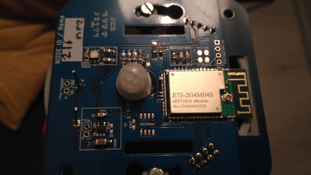
"Currently, the nRF52832 and nRF51822 are supported so we recommend sticking with those for now."I noticed that my board: (E73-2G4M04S) is labeled "NRF52810". So is that why after programming it nothing works (nothing seen on gateway) :( ?
If so, I messed up on that order.
But I am also trying the E73 2G4M04S1B, which at least from the AliExpress order
https://www.aliexpress.com/item/CDEBYTE-E73-2G4M04S-BLE-4-2-5-0-long-distance-100m-2-4GHz-SMD-ARM-Core/32820692238.html?spm=a2g0s.9042311.0.0.27424c4dSKBLn7says it is nRF52832. (It isn't labeled on the board though). For this module, I can't unlock it using "Recover" from nRfgoStudio. It always fails with a message "Recover failed: Unknown error".
From the command line, if I do
nrfjprog.exe -f NRF52 --recover --log
and it comes back immediately with:
Recovering device. This operation might take 30s.
ERROR: Recover failed. Please make sure that the correct device family is given
ERROR: and try again.The key error from the log seems to be:
2018-Dec-27 12:25:22 . . . . . nRF52_power_debug_and_system_regions
2018-Dec-27 12:25:22 . . . . . . nRF52_write_debug_port_register
2018-Dec-27 12:25:22 . . . . . . nRF52_write_debug_port_register: JLink: JLINK_CORESIGHT_WriteAPDPReg(DP reg 0x02, 0x00000000)
2018-Dec-27 12:25:22 . . . . . . nRF52_write_debug_port_register: JLink: returns -1
2018-Dec-27 12:25:23 . . . . . . nRF52_write_debug_port_register: JLink: (0005ms, 0288ms total)
2018-Dec-27 12:25:23 . . . . . . nRF52_write_debug_port_register: JLinkARM.dll CORESIGHT_WriteAPDPReg returned error -1.2018-Dec-27 12:25:23 . . . . . nRF52_power_debug_and_system_regions: JLinkARM.dll CORESIGHT_WriteAPDPReg returned error -102.
If I do: nrfjprog.exe -f NRF51 --recover --log
it actually makes LD5 on the DK board flash for 30 seconds, but still returns failure with the exact same message.
Any other tricks for "recover/unlock" of those boards?
Thanks!
@ileneken3 sorry, can't help you anymore.
I can only tell that I installed the segger drivers, and everything as described by @d00616
Most issues I have, happen when I did some soldering wrong or when I've been messing around with drivers. A clean setup almost always solve my problems
I used both old and new ebyte modules and they work like a charm.
-
Hi,
I'm trying to begin with nrf52832.
I have follow advice, with soldering 4 wires. I use STlink v2, downloading soft before use it.
When i try to erase the nrf52832, with sketch "mass_erase" in exemple, i have the following error :Arduino : 1.8.7 (Windows 10), Carte : "MyBoardNRF5 nRF52832, None, Crystal Oscillator, Don't enable"
C:\Users\Sancho\AppData\Local\Arduino15\packages\sandeepmistry\tools\openocd\0.10.0-dev.nrf5/bin/openocd.exe -d2 -f interface/stlink-v2.cfg -c transport select hla_swd; set WORKAREASIZE 0x4000; -f target/nrf52.cfg -c init; halt; nrf51 mass_erase; program {{{build.core.path}/SDK/components/softdevice/none/hex/none_nrf52_{softdeviceversion}_softdevice.hex}} verify reset; shutdown;
Open On-Chip Debugger 0.10.0-dev-00254-g696fc0a (2016-04-10-10:13)
Licensed under GNU GPL v2
For bug reports, read
http://openocd.org/doc/doxygen/bugs.html
debug_level: 2
0x4000
Info : The selected transport took over low-level target control. The results might differ compared to plain JTAG/SWD
adapter speed: 10000 kHz
Info : Unable to match requested speed 10000 kHz, using 4000 kHz
Info : Unable to match requested speed 10000 kHz, using 4000 kHz
Info : clock speed 4000 kHz
Info : STLINK v2 JTAG v29 API v2 SWIM v7 VID 0x0483 PID 0x3748
Info : using stlink api v2
Info : Target voltage: 3.280426
Error: init mode failed (unable to connect to the target)
in procedure 'init'
in procedure 'ocd_bouncer'Erreur lors de la gravure de la séquence d'initialisation.
I try to upload an empty sketch (MyBoardNRF5), and have this message :
Arduino : 1.8.7 (Windows 10), Carte : "MyBoardNRF5 nRF52832, None, Crystal Oscillator, Don't enable"
Le croquis utilise 10508 octets (2%) de l'espace de stockage de programmes. Le maximum est de 524288 octets.
C:\Users\Sancho\AppData\Local\Arduino15\packages\sandeepmistry\tools\openocd\0.10.0-dev.nrf5/bin/openocd.exe -d2 -f interface/stlink-v2.cfg -c transport select hla_swd; set WORKAREASIZE 0x4000; -f target/nrf52.cfg -c program {{C:\Users\Sancho\AppData\Local\Temp\arduino_build_74329/MyBoardNRF5.ino.hex}} verify reset; shutdown;
Open On-Chip Debugger 0.10.0-dev-00254-g696fc0a (2016-04-10-10:13)
Licensed under GNU GPL v2
For bug reports, read
http://openocd.org/doc/doxygen/bugs.html
debug_level: 2
0x4000
Info : The selected transport took over low-level target control. The results might differ compared to plain JTAG/SWD
adapter speed: 10000 kHz
Une erreur est survenue lors du transfert du croquis
Info : Unable to match requested speed 10000 kHz, using 4000 kHz
Info : Unable to match requested speed 10000 kHz, using 4000 kHz
Info : clock speed 4000 kHz
Info : STLINK v2 JTAG v29 API v2 SWIM v7 VID 0x0483 PID 0x3748
Info : using stlink api v2
Info : Target voltage: 3.280426
Error: init mode failed (unable to connect to the target)
in procedure 'program'
in procedure 'init' called at file "embedded:startup.tcl", line 473
in procedure 'ocd_bouncer'
** OpenOCD init failed **
shutdown command invokedCan you help me please ?
@sancho119 what exact model of a board do you have? Did you try to switch SWDIO and SWCLK, maybe they are messed up? Or lose connection? To erase softdevice you can simply chose Tools>Softdevice>"None" and then press "Burn bootloader" button.
-
Hello
it's a E73 2G4M04S1B from EBYTE
When i switch SWDIO and SWCLK, i can see the led of STLink V2 changing from red to blue, but when i try to uplod empty sketch (MyBoardNRF5), i have this error :C:\Users\Sancho\AppData\Local\Arduino15\packages\sandeepmistry\tools\openocd\0.10.0-dev.nrf5/bin/openocd.exe -d2 -f interface/stlink-v2.cfg -c transport select hla_swd; set WORKAREASIZE 0x4000; -f target/nrf52.cfg -c program {{C:\Users\Sancho\AppData\Local\Temp\arduino_build_432557/MyBoardNRF5.ino.hex}} verify reset; shutdown;
Open On-Chip Debugger 0.10.0-dev-00254-g696fc0a (2016-04-10-10:13)
Licensed under GNU GPL v2
For bug reports, read
http://openocd.org/doc/doxygen/bugs.html
debug_level: 2
0x4000
Info : The selected transport took over low-level target control. The results might differ compared to plain JTAG/SWD
adapter speed: 10000 kHz
Info : Unable to match requested speed 10000 kHz, using 4000 kHz
Info : Unable to match requested speed 10000 kHz, using 4000 kHz
Info : clock speed 4000 kHz
Info : STLINK v2 JTAG v29 API v2 SWIM v7 VID 0x0483 PID 0x3748
Info : using stlink api v2
Info : Target voltage: 3.283200
Info : nrf52.cpu: hardware has 0 breakpoints, 2 watchpoints
Error: timed out while waiting for target halted
TARGET: nrf52.cpu - Not halted
in procedure 'program'
in procedure 'reset' called at file "embedded:startup.tcl", line 478
in procedure 'ocd_bouncer'embedded:startup.tcl:454: Error: ** Unable to reset target **
in procedure 'program'
in procedure 'program_error' called at file "embedded:startup.tcl", line 479
at file "embedded:startup.tcl", line 454
le port série sélectionné at file "embedded:startup.tcl", line 454
n'existe pas ou votre Arduino n'est pas connectée -
Hello
it's a E73 2G4M04S1B from EBYTE
When i switch SWDIO and SWCLK, i can see the led of STLink V2 changing from red to blue, but when i try to uplod empty sketch (MyBoardNRF5), i have this error :C:\Users\Sancho\AppData\Local\Arduino15\packages\sandeepmistry\tools\openocd\0.10.0-dev.nrf5/bin/openocd.exe -d2 -f interface/stlink-v2.cfg -c transport select hla_swd; set WORKAREASIZE 0x4000; -f target/nrf52.cfg -c program {{C:\Users\Sancho\AppData\Local\Temp\arduino_build_432557/MyBoardNRF5.ino.hex}} verify reset; shutdown;
Open On-Chip Debugger 0.10.0-dev-00254-g696fc0a (2016-04-10-10:13)
Licensed under GNU GPL v2
For bug reports, read
http://openocd.org/doc/doxygen/bugs.html
debug_level: 2
0x4000
Info : The selected transport took over low-level target control. The results might differ compared to plain JTAG/SWD
adapter speed: 10000 kHz
Info : Unable to match requested speed 10000 kHz, using 4000 kHz
Info : Unable to match requested speed 10000 kHz, using 4000 kHz
Info : clock speed 4000 kHz
Info : STLINK v2 JTAG v29 API v2 SWIM v7 VID 0x0483 PID 0x3748
Info : using stlink api v2
Info : Target voltage: 3.283200
Info : nrf52.cpu: hardware has 0 breakpoints, 2 watchpoints
Error: timed out while waiting for target halted
TARGET: nrf52.cpu - Not halted
in procedure 'program'
in procedure 'reset' called at file "embedded:startup.tcl", line 478
in procedure 'ocd_bouncer'embedded:startup.tcl:454: Error: ** Unable to reset target **
in procedure 'program'
in procedure 'program_error' called at file "embedded:startup.tcl", line 479
at file "embedded:startup.tcl", line 454
le port série sélectionné at file "embedded:startup.tcl", line 454
n'existe pas ou votre Arduino n'est pas connectée@sancho119 No matter what I tried, I could not unlock the E73 with the STLink.
I had to buy a jlink clone, download a bunch of segger debugging tools, use the segger tools to override the lock flag. After that I could flash the bootloader.
https://github.com/micooke/arduino-nRF5-smartwatches/blob/master/nrf52_disable_read_protection.txt
#To share my experience with the nRF52832. #I was unable to disable the read protection / flash lock with a BMP or ST-Link V2, but i was successful with a J-Link. #When nRF52832 chip is read protected / locked, the first step is to try: nrfjprog –recover -f nrf52 #This performs the same task as: Jlink -if swd -device nrf52 J-Link>SWDSelect J-Link>SWDWriteDP 1, 0x50000000 J-Link>SWDWriteDP 2, 0x01000000 J-Link>SWDWriteAP 1, 0x00000001 #Wait until AP 2 is 0, and the operation is complete J-Link>SWDReadAP 2 #If two successive reads from AP 3 produce 0, then 1 then protection is disabled J-Link>SWDReadAP 3 J-Link>SWDReadAP 3 #Tested with JLink v6.20b -
@sancho119 No matter what I tried, I could not unlock the E73 with the STLink.
I had to buy a jlink clone, download a bunch of segger debugging tools, use the segger tools to override the lock flag. After that I could flash the bootloader.
https://github.com/micooke/arduino-nRF5-smartwatches/blob/master/nrf52_disable_read_protection.txt
#To share my experience with the nRF52832. #I was unable to disable the read protection / flash lock with a BMP or ST-Link V2, but i was successful with a J-Link. #When nRF52832 chip is read protected / locked, the first step is to try: nrfjprog –recover -f nrf52 #This performs the same task as: Jlink -if swd -device nrf52 J-Link>SWDSelect J-Link>SWDWriteDP 1, 0x50000000 J-Link>SWDWriteDP 2, 0x01000000 J-Link>SWDWriteAP 1, 0x00000001 #Wait until AP 2 is 0, and the operation is complete J-Link>SWDReadAP 2 #If two successive reads from AP 3 produce 0, then 1 then protection is disabled J-Link>SWDReadAP 3 J-Link>SWDReadAP 3 #Tested with JLink v6.20b -
-
Hello,
Some news !
i buy a Jlink, and success in erase my nrf52832 with nrf prog, using method of berkseo.Next i try to upload a basic sketch (blink) :
#define MY_RADIO_NRF5_ESB
#include <nrf.h>
#include <MySensors.h>void setup() {
Serial.begin(9600);
hwPinMode(LED_BUILTIN,OUTPUT_H0H1);
}void loop() {
digitalWrite(LED_BUILTIN, HIGH); // turn the LED on (HIGH is the voltage level)
delay(1000); // wait for a second
digitalWrite(LED_BUILTIN, LOW); // turn the LED off by making the voltage LOW
delay(1000); // wait for a second
}I have this :
Open On-Chip Debugger 0.10.0-dev-00254-g696fc0a (2016-04-10-10:13)
Licensed under GNU GPL v2
For bug reports, read
http://openocd.org/doc/doxygen/bugs.html
debug_level: 2
0
adapter speed: 10000 kHz
cortex_m reset_config sysresetreq
Info : No device selected, using first device.
Info : J-Link ARM-OB STM32 compiled Aug 22 2012 19:52:04
Info : Hardware version: 7.00
Info : VTarget = 3.300 V
Info : clock speed 10000 kHz
Info : SWD IDCODE 0x2ba01477
Info : nrf52.cpu: hardware has 6 breakpoints, 4 watchpoints
nrf52.cpu: target state: halted
target halted due to debug-request, current mode: Thread
xPSR: 0x01000000 pc: 0x0000051c msp: 0x20010000
** Programming Started **
auto erase enabled
Warn : Unknown device (HWID 0x00000139)
Warn : not enough working area available(requested 32)
Warn : no working area available, falling back to slow memory writes
wrote 12288 bytes from file C:\Users\Sancho\AppData\Local\Temp\arduino_build_76789/NRF5_blink_led8.ino.hex in 4.155332s (2.888 KiB/s)
** Programming Finished **
** Verify Started **
Warn : not enough working area available(requested 52)
verified 10812 bytes in 0.165932s (63.632 KiB/s)
** Verified OK **
** Resetting Target **
shutdown command invokedI think its good, but when i put a led with a resistance on P0.08, nothing :(
could you help me more ?
@sancho119 said in GUIDE - NRF5 / NRF51 / NRF52 for beginners:
Hello,
Some news !
i buy a Jlink, and success in erase my nrf52832 with nrf prog, using method of berkseo.Next i try to upload a basic sketch (blink) :
#define MY_RADIO_NRF5_ESB
#include <nrf.h>
#include <MySensors.h>void setup() {
Serial.begin(9600);
hwPinMode(LED_BUILTIN,OUTPUT_H0H1);
}void loop() {
digitalWrite(LED_BUILTIN, HIGH); // turn the LED on (HIGH is the voltage level)
delay(1000); // wait for a second
digitalWrite(LED_BUILTIN, LOW); // turn the LED off by making the voltage LOW
delay(1000); // wait for a second
}I have this :
Open On-Chip Debugger 0.10.0-dev-00254-g696fc0a (2016-04-10-10:13)
Licensed under GNU GPL v2
For bug reports, read
http://openocd.org/doc/doxygen/bugs.html
debug_level: 2
0
adapter speed: 10000 kHz
cortex_m reset_config sysresetreq
Info : No device selected, using first device.
Info : J-Link ARM-OB STM32 compiled Aug 22 2012 19:52:04
Info : Hardware version: 7.00
Info : VTarget = 3.300 V
Info : clock speed 10000 kHz
Info : SWD IDCODE 0x2ba01477
Info : nrf52.cpu: hardware has 6 breakpoints, 4 watchpoints
nrf52.cpu: target state: halted
target halted due to debug-request, current mode: Thread
xPSR: 0x01000000 pc: 0x0000051c msp: 0x20010000
** Programming Started **
auto erase enabled
Warn : Unknown device (HWID 0x00000139)
Warn : not enough working area available(requested 32)
Warn : no working area available, falling back to slow memory writes
wrote 12288 bytes from file C:\Users\Sancho\AppData\Local\Temp\arduino_build_76789/NRF5_blink_led8.ino.hex in 4.155332s (2.888 KiB/s)
** Programming Finished **
** Verify Started **
Warn : not enough working area available(requested 52)
verified 10812 bytes in 0.165932s (63.632 KiB/s)
** Verified OK **
** Resetting Target **
shutdown command invokedI think its good, but when i put a led with a resistance on P0.08, nothing :(
could you help me more ?
LED_BUILTIN corresponds to po17
-
-
Hi. Are the steps in first post still valid please?
I'm trying without luck to get first nrf52 programmed. I get a weird error"Error resolving FQBN: missing" in Arduino IDE when I try to verify any basic sketch, even blink. Thanks for any thoughts
-
@p359 Which version of Arduino IDE are you using? I was seeing that with 1.8.10, but I ended up downgrading to 1.8.6 to test and it worked.
-
Hi,
Is it possible to get Serial output in Arduino IDE for nRF52 boards with J-Link OB 7.0? Or do I need a newer programmer? Or maybe I can get it with ST-Link v2/v2.1 somehow?
@martinc said in GUIDE - NRF5 / NRF51 / NRF52 for beginners:
Hi,
Is it possible to get Serial output in Arduino IDE for nRF52 boards with J-Link OB 7.0? Or do I need a newer programmer? Or maybe I can get it with ST-Link v2/v2.1 somehow?
The answer is actually in the first post.
-
@alowhum said in GUIDE - NRF5 / NRF51 / NRF52 for beginners:
The answer is actually in the first post.
Thanks, I've seen it before. In my case a programmer is easier solution - I don't know yet how to re-assign TX&RX pins in Arduino on my EByte 52840 module and in specs for that module there is no info about UART connectivity.
Maybe you know how can I re-assign TX&RX pins in Arduino? Then I can solder wires to assigned TX&RX pins and connect them to USB-UART. What I've found is in Forth language ... -
Does anyone know what settings I need to use for this development board with arduino ide?
Ebyte E104-BT5032A-TB
https://a.aliexpress.com/_dT5dMb8It has a cp2102 on board which I have the driver for. I've installed the arduino ide nrf52 board, but I can't find a programmer, board, or any other settings which will let me flash it without a Java exception or a timeout. Maybe I need to set the jumpers differently but there's no documentation on that.
OTA works fine though. -
Does anyone know what settings I need to use for this development board with arduino ide?
Ebyte E104-BT5032A-TB
https://a.aliexpress.com/_dT5dMb8It has a cp2102 on board which I have the driver for. I've installed the arduino ide nrf52 board, but I can't find a programmer, board, or any other settings which will let me flash it without a Java exception or a timeout. Maybe I need to set the jumpers differently but there's no documentation on that.
OTA works fine though.@idanronen this is a UART to BT module, and from what I understand in the documentation the CP2102 is only here to give you access to the serial port of the module, but not to program it ?
To program it you will have to use the SWDIO/SWDCLK pins I suppose, and I'm interested to know if it can be reprogrammed because that would make a tiny NRF52832 module for boards that don't require many IOs.
-
@idanronen this is a UART to BT module, and from what I understand in the documentation the CP2102 is only here to give you access to the serial port of the module, but not to program it ?
To program it you will have to use the SWDIO/SWDCLK pins I suppose, and I'm interested to know if it can be reprogrammed because that would make a tiny NRF52832 module for boards that don't require many IOs.
@Nca78 I feared that might be the case. my task for today was to dig up my st-link and try that, though I hoped I might have done something wrong and the cp2102 can be used to program and not just debug.
That module is pretty cheap and from what I see with the naked eye, you can disconnect the cp2102 with the jumpers so the power consumption might actually be good enough to use as-is.
I'll report back to let you know once I've succeeded