Navigation

    • Register
    • Login
    • OpenHardware.io
    • Categories
    • Recent
    • Tags
    • Popular
    1. Home
    2. ahmedadelhosni
    3. Best
    • Profile
    • Following
    • Followers
    • Topics
    • Posts
    • Best
    • Groups

    Best posts made by ahmedadelhosni

    • [Tutorial] How to burn 1Mhz & 8Mhz bootloader using Arduino IDE 1.6.5-r5

      Hello everyone,

      Last week I received my slim node board designed by m26872 and begun the process of burning the 1Mhz bootloader. I faced some problems for a couple of hours and google helped me to successfully burn it and uploading the sketch.
      Please correct me if I missed something. I tried to re-do the steps now before writing the post to make sure it works.

      I am using Arduino IDE 1.6.5-r5 with Arduino UNO board.
      I used some photos from arduino.cc
      I will explain flashing both 8Mhz and 1Mhz configurations.

      1- You will need the following

      • Arduino UNO ( didn't test using other boards)
      • Atmega328p chip ( with preloaded bootloader or without )
      • Breadboard
      • Wires
      • Crystal ( optional )

      2-

      • Connect your arduino UNO to your laptop.
      • Open Arduino IDE.
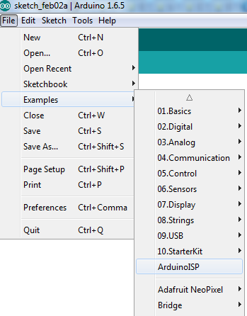
      • Go to File > Examples > Arduino ISP

      0_1454446970268_1.png

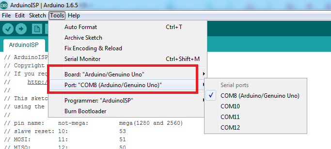
      • Go to Tools and make sure you choose Arduino/Genuino Uno and you COM port.
        Your COM port may be different than mine

      0_1454447281880_2.png

      Note: The following step solved my problem when I failed to upload the bootloader at the beginning.

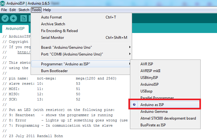
      • Go to Tools > Programmer > Arduino as ISP

      Make sure to choose "Arduino as ISP" not "ArduinoISP"

      0_1454447412898_3.png

      Then upload your ArduinoISP sketch.

      • It will take less than a minute.
      • Close the sketch ArduinoISP adter uploading successfully.

      *********************************** . ***********************************
      *********************** Burning the bootloader ***********************
      *********************************** . ***********************************

      3- For burning the bootloader you have to set your environment as shown in the figure below:
      Remove the arduino usb cable and begin wiring.

      0_1454446598443_4.png

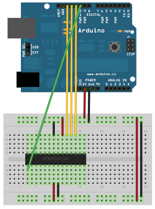
      Double check your wires and make sure they are connected in the correct pin.

      *********************************** . ***********************************
      ********************** Burning 8Mhz bootloader **********************
      *********************************** . ***********************************

      Quoted from Arduino.cc :

      • Download this hardware configuration archive: breadboard-1-6-x.zip
      • Extract the zip file. A folder with name "breadboard" will appear.
      • Open your Arduino folder path and move the breadboard folder from the zip archive to the "hardware" folder of your Arduino sketchbook.
      • Restart the Arduino software.
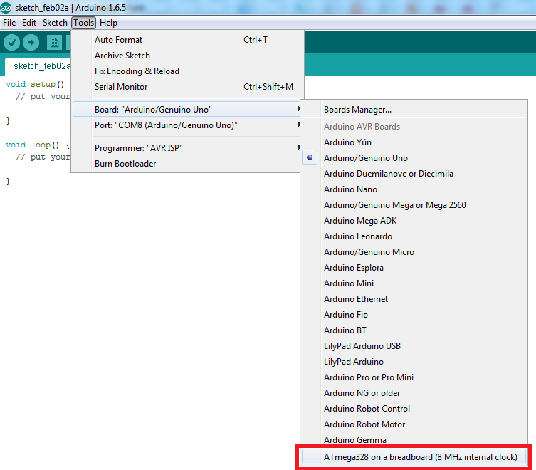
        You should see "ATmega328 on a breadboard (8 MHz internal clock)" in the Tools > Board menu.
      • Be sure to select "ATmega328 on a breadboard (8 MHz internal clock)" when burning the bootloader.(If you select the wrong item and configure the microcontroller to use an external clock, it won't work unless you connect one.)
      • Once you've done this, you can burn the bootloader and upload programs onto your ATmega328p. To burn the bootloader go to Tools > Burn bootloader

      0_1454448243570_5.png

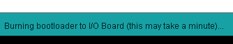
      It will take less than a minute and leds will flash. Wait until bootloader is burned.

      0_1454448363854_6.png

      *********************************** . ***********************************
      ********************** Burning 1Mhz bootloader **********************
      *********************************** . ***********************************

      • I followed m26872 guides in his project My Slim 2AA Battery Node to get the 1Mhz bootloader. I'll copy some of his instructions.

      • I use this precompiled bootloader from here. It's an Optiboot with 1MHz internal clock and 9600 baud serial communication. Fuse changed to BOD disable.

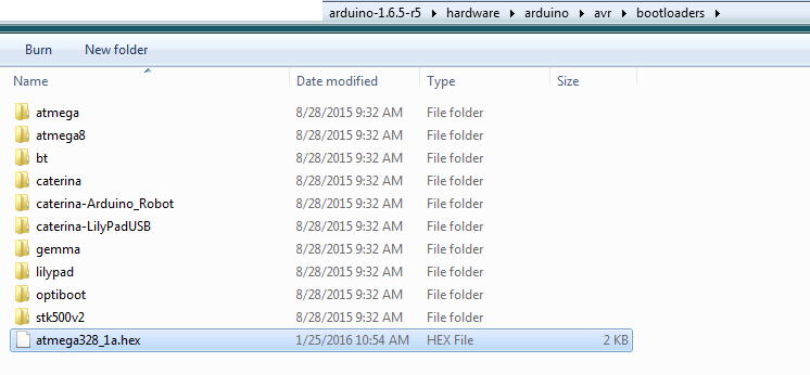
      • Rename your .hex to atmega328_1a.hex

      • Move it to "ARDUINO_PATH" > hardware > arduino > avr > bootloaders

      0_1454448897446_8.png

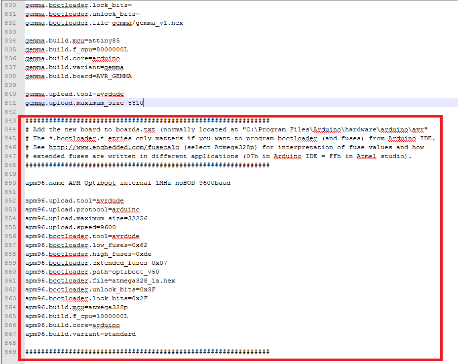
      • We need to add the new board to the boards.txt file located at "ARDUINO_PATH" > hardware > arduino > avr
      • Open boards.txt
      • Go to this link.
      • Copy the content of the link and paste it at the end of boards.txt

      0_1454449112046_9.png

      • Restart you Arduino IDE.
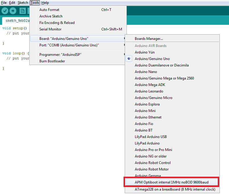
      • You should see "APM Optiboot internal 1Mhz noBOD 9600baud" in the Tools > Board menu.
      • Once you've done this, you can burn the bootloader and upload programs onto your ATmega328p. To burn the bootloader go to Tools > Burn bootloader

      0_1454451123401_10.png

      Tips about burning the bootloader if it failed:

      1- I faced the following issues and was solved as follows:

      avrdude: Yikes! Invalid device signature.
      Double check connections and try again, or use -F to override

      • Maybe your chip is configured to run on an external crystal clock. I tested with two values and it succeeded. I used 10Mhz and 20Mhz as I didn't have 16 Mhz.
      • Connect the crystal to pin 9 and 10
      • Note: You won't need the crystal except for the first time as the new bootloader is configured to run on internal 1Mhz or 8Mhz.

      2-

      avrdude: Error: Could not find USBtiny device (0x2341/0x49)

      Make sure you chose "Arduino as ISP" not "ArduinoISP" from the programmer list. You will find it in Tools menu.

      3-

      avrdude: can't open input file D:\arduino-1.6.5-r5\hardware\arduino\avr/bootloaders/atmega328_1a.hex: No such file or directory
      avrdude: read from file 'D:\arduino-1.6.5-r5\hardware\arduino\avr/bootloaders/atmega328_1a.hex' failed
      Error while burning bootloader.

      Your .hex file is not in the correct path.

      • According to the .boards file, the path is configured to be in the default path arduino-1.6.5-r5\hardware\arduino\avr\bootloaders

      You can find this configuration in the boards.txt as follows:
      apm96.bootloader.file=atmega328_1a.hex

      If you wish to put the .hex file in a folder, so you will have to edit the path above in the boards.txt

      Example:You put the .hex file in > arduino-1.6.5-r5\hardware\arduino\avr\bootloaders\MyOneMhz
      So change the line to this: apm96.bootloader.file=MyOneMhz/atmega328_1a.hex

      *********************************** . ***********************************
      ********************** End of burning bootloader **********************
      *********************************** . ***********************************

      *********************************** . ***********************************
      ************************ Uploading the sketch *************************
      *********************************** . ***********************************

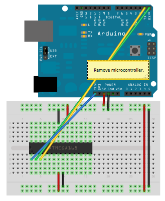
      4- Once your ATmega328p has the Arduino bootloader on it, you can upload programs to it using the USB-to-serial convertor (FTDI chip) on an Arduino board. To do so, you remove the microcontroller from the Arduino board so the FTDI chip can talk to the microcontroller on the breadboard instead.

      • Set the environment as follows:
        The picture at the bottom shows how to connect the RX and TX lines from the Arduino UNO board to the ATmega on the breadboard.

      0_1454449899848_7.png

      After finishing wiring and recheck connections:

      • Choose your desired board which we have added before and burned the atmega328p with it.
      • Upload your sketch normally.
      • Leds will flash in the Arduino UNO board.
      • Sketch will take some time with 1Mhz and it is faster with 8Mhz because of the baud rate chosen in 1Mhz.

      *********************************** . ***********************************
      *************************** ** References ** **************************
      *********************************** . ***********************************

      • How To Load Bootloader onto Arduino
      • Re: Burning bootloader on standalone Atmega328(internal clock 8MHz)
      • From Arduino to a Microcontroller on a Breadboard

      *********************************** . ***********************************
      *************************** ** THE END ** *****************************
      *********************************** . ***********************************

      I hope it was clear enough and doesn't contain mistakes. Please let me know if something was missing.
      I encourage you to add your tips and tricks so that we can learn.

      Thanks.

      posted in Development
      ahmedadelhosni
      ahmedadelhosni
    • RE: Step-by-step procedure to connect the NRF24L01+ to the GPIO pins and use the Raspberry as a Serial Gateway (MySensors 1.x)

      Great and simple.
      Is connecting the nrf directly to the pi causes any problems and u need to restart it ?
      Thanks.

      posted in Hardware
      ahmedadelhosni
      ahmedadelhosni
    • RE: LDO 9 volt

      I was thinking about ordering MCP1702. It has 2us quiescent current.

      posted in Hardware
      ahmedadelhosni
      ahmedadelhosni
    • RE: GatewayESP8266MQTTClient in Development Branch

      Hello,

      This reply is related to another topic http://forum.mysensors.org/topic/2378/how-can-i-set-the-payload-for-mqtt-v1-6 where I wasn't able to send my buffer from my mqtt gateway to another sensor node. After spending all day today debugging the issue, I was able to find two bugs and to send the buffer correctly.

      This is the topic which I subscribe to

      #define MY_MQTT_SUBSCRIBE_TOPIC_PREFIX "mygatewayin"
      

      This is how I send my mqtt pattern using MQTTlens or Mosquitto to be published to the gateway. My message contains 1 or 0 to turn ON or OFF a relay in my sensor node with id 4, child id 19, set, no ack, V_LIGHT

      mygatewayin/4/19/1/0/2
      

      The first problem which I faced is that my mqtt buffer wasn't evaluated in the callback function incomingMQTT() found in MyGatewayTransportMQTTClient.cpp

      After checking the case switch I found out that the rest of the case switches doesn't continue because the code returns due to the following line

      if (strcmp_P(str, MY_MQTT_SUBSCRIBE_TOPIC_PREFIX) != 0)
      {
          return;
      }
      

      According to http://www.nongnu.org/avr-libc/user-manual/group__avr__pgmspace.html#gad34d5b7d040fcb97939e939f19d88a5f

      The strcmp_PF() function returns an integer less than, equal to, or greater than zero if s1 is found, respectively, to be less than, to match, or be greater than s2. The contents of RAMPZ SFR are undefined when the function returns

      Actually I haven't used this function before but according to description it will return 0 if they are identical, so using != shall be right, but actually it was solved when I replaced it with == instead of !=

      Finally I was able to evaluate the buffer and the case switches continued.

      But Also this didn't solve the problem and the buffer wasn't sent to the sensor node id 4

      After lots of printing functions for debugging I found that in serial monitoring, the following is printed

      send: 0-0-0-4 s=19,c=1,t=2,pt=0,l=1,sg=0,st=fail:1
      

      While when I use Serial gateway which is working well till now, the following is printed instead

      send: 0-0-4-4 s=19,c=1,t=2,pt=0,l=1,sg=0,st=ok:1
      

      Thus I found that the difference is in 0-0-X-4.

      Searching further in the code, I found that the debug function for this line is used in MyTransport.cpp in function transportSendWrite(uint8_t to, MyMessage &message)

      debug(PSTR("send: %d-%d-%d-%d s=%d,c=%d,t=%d,pt=%d,l=%d,sg=%d,st=%s:%s\n"),
      			message.sender,message.last, to, message.destination, message.sensor, mGetCommand(message), message.type,
      			mGetPayloadType(message), mGetLength(message), mGetSigned(message), to==BROADCAST_ADDRESS ? "bc" : (ok ? "ok":"fail"), message.getString(_convBuf));
      

      So the difference here is that the variable to is set as 0 in case of mqttgateway, while it is set as 4 correctly using Serial gateway.

      So finally this is what I have reached.

      In MyTransport.cpp in function boolean transportSendRoute(MyMessage &message)

      #if !defined(MY_REPEATER_FEATURE)
          // None repeating node... We can only send to our parent\\
          ok = transportSendWrite(_nc.parentNodeId, message);
      #endif
      

      The above is called because MY_REPEATER_FEATURE is not defined, thus the mqttgateway sends always 0 instead of the required node id.

      I tried to define MY_REPEATER_FEATURE but I found big memory size and the software was crazy.
      Also in MySensor.h it is not mentioned to be defined

      #if defined(MY_GATEWAY_MQTT_CLIENT)
      ... some code ...
      ... some code ...
      #elif defined(MY_GATEWAY_FEATURE)
      ... some code ...
      	#if defined(MY_RADIO_FEATURE)
      		// We assume that a gateway having a radio also should act as repeater
      		#define MY_REPEATER_FEATURE
      	#endif
      

      What I did now as a workaround because it is 2:40 AM here and I need to sleep 😄 Is the following

      In MyTransport.cpp

      	#if !defined(MY_REPEATER_FEATURE)
      		#if defined(MY_GATEWAY_MQTT_CLIENT)
      			ok = transportSendWrite(message.destination, message);
      		#else
      		// None repeating node... We can only send to our parent
      		ok = transportSendWrite(_nc.parentNodeId, message);
      		#endif
      	#else
      

      Please check whether this will solve the problem or not. Please correct me if I was wrong. It's my first time to look around in the library today.

      Thanks.

      posted in Development
      ahmedadelhosni
      ahmedadelhosni
    • RE: My Slim 2AA Battery Node

      First node. Door sensor.
      Great boards :+
      0_1453937636107_1453937611984-964477924.jpg

      0_1453938444465_1453938399889-988876899.jpg

      .

      posted in My Project
      ahmedadelhosni
      ahmedadelhosni
    • RE: Are Chinese power supply chargers that dangerous to use ?

      @icebob After I have read almost most of the replies in the thread "safe in wall ... " I would tell you don't ever use this. This is even worse that charger number 1 and 2 which I posted above.

      After reading about safe circuits. The idea is that you need to protect all your component from damage and to avoid any overheating + you want a clean steady output.

      What i see now that there is no fuse nor varistor components at the AC input. The circuit uses only one diode for rectifying - the one at the upper right - not too bad but I read that a full wave rectifier with four diodes gives cleaner output. Other good circuits have an IC to control the output with feedback and has inbuilt over voltage / over current / over thermal protection. This one uses only transistor with - I guess - the other transistor for feedback. Another bad thing is that there is no isolation at all between high side voltage and low side voltage. The optocoupler in the middle should handle this in a better circuit desing, plus, there is no Y capacitor for isolation. ( See charger number 3, you will find an empty space in the middle and a blue component which is the Y capacitor )

      Thus this is a really simple AC to DC charger but with less protection and probably won't provide you with stable voltage. I don't encourage you to use this. You can check the two threads in my origianl post. They use HLK which is a great circuit design as a step down converter.

      posted in Hardware
      ahmedadelhosni
      ahmedadelhosni
    • RE: [SOLVED] Gateway as a sensor node in v1.6

      Yeah you solved this issue now. That's exactly what I needed 🙂

      The second picture explains it all. I wasn't able to understand how will I have several GWs although you explained it above from the beginning, but I wasn't aware how to do it. I remembered now from your last picture that domoticz can support several hardware. Thus I can make another GW and add it to the hardware in Domoticz as you have explained in your last picture.

      Thanks a lot for your time. Now it is very clear 🙂

      posted in Development
      ahmedadelhosni
      ahmedadelhosni
    • PINE A64, First $15 64-Bit Single Board Super Computer

      Hello.

      Did anyone check this great board on Kickstarter ? https://www.kickstarter.com/projects/pine64/pine-a64-first-15-64-bit-single-board-super-comput/description

      It shall be more powerful than Raspberry Pi 2. It is clear from its name that it is 64 bit. It is 1.2 Ghz clock + 1 or 2 GB of Ram. There are many great other features like the powerful Video output.

      What I like the most is that they stated directly that it is compataible with OpenHab controller.

      What do you think ?

      I backed them today and shipping is next march. Not bad at all for me.

      posted in General Discussion
      ahmedadelhosni
      ahmedadelhosni
    • RE: My Slim 2AA Battery Node

      @meddie
      0_1454272780491_1453938474660-1453938399889-988876899.jpg

      The sensor is drawn by black rectangle. This is adhesive tape like this : http://2.imimg.com/data2/YX/UQ/MY-3910304/sale-bopp-clarity-adhesive-tape-250x250.jpg

      The other red rectangle on the door was old tape I didn't remove. Actually before getting my boards I used a bread board and a battery for testing, so I needed a tape for support and keeping it in place 🙂

      posted in My Project
      ahmedadelhosni
      ahmedadelhosni
    • RE: MYSBootloader 1.3 pre-release & MYSController 1.0.0beta

      @scalz great.
      This means that MYSBootloader can handle this problem and enter the bootloader mode even if the MCU freezes.

      @tekka you state that the current version can handle a freeze SW. Also if the new code is corrupted during programming by unverified CRC or whatever, it will also handle that problem and resets and wait for a new flashing order.
      Is this new in this version ? I am some how sure that MYSBootloader previously had a problem handling thoses types of failures, and that's why I was going to use DualOptiboot as I read before that it can handle those failures

      Sorry for lots of questions but I am trying to reorganise my info.

      posted in Development
      ahmedadelhosni
      ahmedadelhosni
    • RE: Signing or encrypting the data

      @Anticimex Great. now it is very clear 🙂 Thanks a lot

      I will order all ICs soon and test this in real life 🙂

      posted in General Discussion
      ahmedadelhosni
      ahmedadelhosni
    • RE: 2 channel in wall dimmer

      @Denke Yeah the holiday takes a long period there 🙂

      Actually yesterday I read a lot about AC-DC converters and really learned new things, but I may need your help in clarifying some points please. I watched this video which guided me to this type of circuit design. Modlet Smart-Outlet Teardown and Review - (IT'S A POS)

      Be aware that by this type of design with the transformer less design considerations needs to be taken when connecting computers and other stuff.

      1- What I learned yesterday is that a "transformless" design is not safe ( don't know to what level of safety though ), but I read that there is no isolation between Main inputs and low voltage.
      My questions:

      • Is this normal ? Would that affect the Atmega and other components ?
      • How to avoid this ?

      2- The above video mentioned that the Modlet outlet uses LNK304DN Datasheetwith outputs 12V. The below picture is from the datasheet and that reference was even used in the Modlet outlet as mentioned in the video.

      0_1454769854531_upload-006ff262-c868-415c-89c6-6d859b964de8

      My question:

      • There are different designs in the datasheet but I can't diffrentiate between them and what is the best to use, but in all cases, this design still lacks the safety procedures, correct ? Like there is no MOV, Fuse .. ? It is just the circuit to produce a 12V 120mA which shall be stable and not noisy. Correct ?

      3-

      The AC is on the left hand side. the 0.33 uF capacitor in series on the 240 sets the maximum current, which should be around 10 mA on the AC side

      I then changed some parts as the transformerless design would in simulation not give more than 10mA so I added the MAX 17552 circuit in between and set the input voltage to 24 V with the zener diode and by that I will be able to draw about 30 mA (starting current of the circuit that I tested is around 24 mA).
      Can you explain what the 0.33 uF does to set the maximun current ?

      • What is the maximum current and how was it calculated ?
      • How can I increase the output current to 100mA 5v/3.3v ?
      • Actually the schematic is not clear at all when I download the pictuers. Maybe resolution 🙂

      Thanks a lot for your support.

      posted in My Project
      ahmedadelhosni
      ahmedadelhosni
    • RE: [security] Introducing signing support to MySensors

      @Anticimex Okay I managed to get it working .. I guess 💃

      After I posted here I decided to go through the code to see when this TAMPERED is printed, so I thought from debugging that this is related to hwReadConfigBlock so I decided to clear the EEPROM, re personilize the gateway and reflash the GW sketch ... Now I get SGN:PER:OK

      I then reflashed my sensor node again and I guess it is working now .. I tried sending 1;1;1;1;2;1 through serial and this is the result

      0;255;3;0;9;429250 SGN:SKP:MSG CMD=3,TYPE=16
      0;255;3;0;9;429266 TSF:MSG:SEND,0-0-1-1,s=1,c=3,t=16,pt=0,l=0,sg=1,ft=0,st=OK:
      0;255;3;0;9;429287 SGN:SGN:NCE REQ,TO=1
      0;255;3;0;9;429391 TSF:MSG:READ,1-1-0,s=255,c=3,t=17,pt=6,l=25,sg=0:<NONCE>
      0;255;3;0;9;429412 SGN:NCE:FROM=1
      0;255;3;0;9;429422 SGN:BND:NONCE=882805C056A850AF00469170FEB702EB5B09EC1FEE51D2F22DAAAAAAAAAAAAAA
      0;255;3;0;9;429557 SGN:BND:HMAC=6DB4F3CF2F17E42A5508B4A411CA1478582D052A249A278689D26A7A0B96FBA2
      0;255;3;0;9;429584 SGN:SGN:SGN
      0;255;3;0;9;429594 TSF:MSG:SEND,0-0-1-1,s=1,c=1,t=2,pt=0,l=1,sg=1,ft=0,st=OK:1
      0;255;3;0;9;429740 TSF:MSG:READ,1-1-0,s=1,c=1,t=2,pt=0,l=1,sg=0:1
      0;255;3;0;9;429758 TSF:MSG:ACK
      1;1;1;1;2;1
      

      I guess this means that signing is working .. I did try also to add another gateway with no signing and it only discovered my node (1) but I got NACK when trying to send to it.

      Am I correct in my analysis ?

      Thanks for the help.

      posted in Development
      ahmedadelhosni
      ahmedadelhosni
    • RE: Signing or encrypting the data

      @meddie Sure. Maybe by the end of that month I may begin in OTA process.
      I hope I can find good documentation 🙂

      posted in General Discussion
      ahmedadelhosni
      ahmedadelhosni
    • RE: AC light dimmer with 2x TRIAC

      I wanted to post this topic in the general discussion as I want to make a "safe" AC control circuit and wanted some ideas.

      I have already designed this circuit 2 years ago but every while I gain some new experience. I was programming the dimmer using PIC and I was using Real Time Operating System (RTOS) + using (delay) to create an accurate timing for firing the TRIAC after the Zero crossing is detected. It worked very fine. Ofcourse using delay is bad and blocks your code.
      Afterwards I changed my code to use time interrupts instead of RTOS, and flickering was happening sometimes.
      I am telling you this because this may be something wrong in your coding. So this is the first issue you have to revise.

      Second. A few months ago I found a better design in this link . It is also a dimmer circuit but I read the comments and people said that there is no choke component in the circuit. I read later and new that this means that an inductor must be added ( don't know where exactly ) but I knew later that pulsing in such circuits is not safe without a choke components. This may also cause this flicker as I have on some sites.

      Third. I had a friend of mine who used to run his Home Automation for 3 years. He used the same simple design as you and he never reported any bad issues 🙂 This really made me confused, as the link which I have shared above contains more componets ( capactitors + snubber circuit ) for safety, while my friend didn't add them. I have also to add that snubber circuits are needed with inductive loads only, and maybe this is way he didn't face any problem.

      ohhh what a long reply 🙂

      posted in My Project
      ahmedadelhosni
      ahmedadelhosni
    • RE: [security] Introducing signing support to MySensors

      @Anticimex aha okay I understand a bit now. So we put s special hmac that does all cryptography jobs then it gives us something that is used for transmision?

      Looks like i have to read the datasheet also 😄

      posted in Development
      ahmedadelhosni
      ahmedadelhosni
    • RE: Does clock speed differs with repeater node ?

      Great and clear explanation @tbowmo . Thanks a lot.

      Thanks @scalz for the link. I read it and it was useful.

      posted in General Discussion
      ahmedadelhosni
      ahmedadelhosni
    • RE: Can other sensors send data to my mysensors?

      @mfalkvidd yeah right. I didn't read the whole replies again.

      I guess this changing the base_id is a good solution as it has large scale. Changing the Fre may be needed if there was radio interference between the two nodes.

      Thanks all.

      posted in General Discussion
      ahmedadelhosni
      ahmedadelhosni
    • RE: Alternatives for nRF24L01+ ?

      @NeverDie @arraWX I ordered 10 from the buyer on ebay .. they sent me 2 free antennas.

      posted in General Discussion
      ahmedadelhosni
      ahmedadelhosni