Skip to content
  • MySensors
  • OpenHardware.io
  • Categories
  • Recent
  • Tags
  • Popular
Skins
  • Light
  • Brite
  • Cerulean
  • Cosmo
  • Flatly
  • Journal
  • Litera
  • Lumen
  • Lux
  • Materia
  • Minty
  • Morph
  • Pulse
  • Sandstone
  • Simplex
  • Sketchy
  • Spacelab
  • United
  • Yeti
  • Zephyr
  • Dark
  • Cyborg
  • Darkly
  • Quartz
  • Slate
  • Solar
  • Superhero
  • Vapor

  • Default (No Skin)
  • No Skin
Collapse
Brand Logo
barduinoB

barduino

@barduino
About
Posts
145
Topics
8
Shares
0
Groups
0
Followers
0
Following
0

Posts

Recent Best Controversial

  • Garage door contraption (yet another)
    barduinoB barduino

    Hi Folks

    After leaving my garage door open all night for several times, I had to go ahead and make a MySensors contraptions for it.

    The garage door system I have has 1 single button it will either open or close the door depending on position, the safety beams and the last operations.

    Since I know nothing about electronics, hacking the motor electronics was beyond my skill set, so I decide to sensorize the button operations. In order to figure out if the door was opening or closing I used a sonic distance relative to de door rail. I was expecting to have issues with precision but I was rather surprised it worked so well.

    0_1490546766426_IMG_0839.JPG

    The base is the fantastic Easy/Newbie PCB for MySensors by @sundberg84 with a bumper/box of my own creation.

    0_1490546914831_IMG_0837.JPG

    Coupled with some extra pieces as the rail support, the insert for the sonic sensor and the box lid it self.

    0_1490547095237_IMG_0838.JPG

    On the controller it looks like this

    With door Open

    0_1490547164135_Haall_door_open.png

    With door Closed

    0_1490547193667_Haall_door_close.png

    On the other side, I've created a simple led sensor which receives a door open/closed signal directly from the garage sensor to turn on or off a led.

    0_1490547492607_IMG_0840.JPG

    As always feedback is appreciated

    Cheers

    My Project

  • Serial Gateway w/ MQTT using nodeJS
    barduinoB barduino

    Hi Folks

    While adding mqtt feature to my controller and inspired by @cranky and his node-red controller, I've created a simple nodejs app to do 2 things:

    • Get the information from the serial gateway and publish it to a broker
    • Subscribe from the broker and send it to the serial gateway.

    Here is the app.js

    // LIBS
    var com = require("serialport");
    var mqtt = require('mqtt');
    
    // SERIAL PORT SETTINGS
    var serial_port = '/dev/ttyACM0';
    // var serial_port = 'COM3'; // windows
    
    // MQTT SETTINGS
    var mqtt_host     = 'mqtts://m10.cloudmqtt.com';
    var mqtt_port     =  8883;
    var mqtt_username =  'user name';
    var mqtt_password =  'password';
    
    var KEY = 'yourkey';
    
    // publications will be made into /haall/yourkey/out/x/x/x/x
    // subcriptions will come from /haall/yourkey/in/x/x/x/
    // adjust as necessary
    
    // MQTT CLIENT OPTIONS
    var mqtt_Options = {
         port:              mqtt_port
        ,keepalive:         10                  //seconds, set to 0 to disable
        ,clientId:          'haall_' + KEY
        ,protocolId:        'MQTT'
        //,protocolVersion: 4
        ,clean:             false               //set to false to receive QoS 1 and 2 messages while offline
        ,reconnectPeriod:   1000                // milliseconds, interval between two reconnections
        ,connectTimeout:    30 * 1000           //milliseconds, time to wait before a CONNACK is received
        ,username:          mqtt_username       //the username required by your broker, if any
        ,password:          mqtt_password       //the password required by your broker, if any
        /*
        ,incomingStore: , // a Store for the incoming packets
        ,outgoingStore: , // a Store for the outgoing packets
        */
        //a message that will sent by the broker automatically when the client disconnect badly. The format is:
        ,will: {topic:  '/haall/'+KEY+'/out',                           // the topic to publish
                payload:'Client haall_' + KEY +'has lost connection',   // the message to publish
                qos:    1,                                              // the QoS
                retain: false                                           // the retain flag 
        }    
    }
    
    // SERIAL PORT
    var serialPort = new com.SerialPort(serial_port, {
        baudrate: 115200,
    	parser: com.parsers.readline('\n')
      });
    
    // START SERIAL PORT 
    console.log('Opening Serial port...');
    serialPort.open(function (error) {
      if ( error ) {
        console.log('failed to open: '+error);
      } else {
        console.log('Serial port opened!');
      }
    });
    
    // START MQTT
    console.log('Starting MQTT...'); 
    var mqtt_client  = mqtt.connect(mqtt_host,mqtt_Options);
    
    console.log('Subscribing MQTT...'); 
    mqtt_client.subscribe('/haall/'+KEY+'/in/#');
    
    console.log('Publish MQTT...'); 
    mqtt_client.publish('/haall/'+KEY+'/out', 'HAALL mqtt client started at '+ new Date());
    
    // SERIAL PORT OUTGOING
    serialPort.on('data', function(data) {
    	
    	if (data.indexOf('0;0;3;0;9;') == 0) {
    		console.log('        I_LOG: '+data);
            mqttPublish(data);	
    	}
    	else{
    		console.log(data);
    		mqttPublish(data);
    	}
    });
    
    // MQTT INCOMING
    mqtt_client.on('message', function (topic, message) {
    	var m = topic.toString();
    	m = m.replace('/haall/'+KEY+'/in/','');
    	m = m.split('/').join(';');
    	m = m + ';' + message.toString();
    	serialPort.write('' + m + '\n');
    
      	console.log('INCOMING MQTT: ' + topic + ':' + message.toString());
    });
    
    // MQTT OUTGOING
    function mqttPublish(data){
    	var topic = '/haall/'+KEY+'/out/';
    	var params = data.split(';');
    	topic = topic + params[0] + '/';
    	topic = topic + params[1] + '/';
    	topic = topic + params[2] + '/';
    	topic = topic + params[3] + '/';
    	topic = topic + params[4] + '';
    	var payload = params[5];
    	mqtt_client.publish(topic,payload);
    	console.log('OUTGOING MQTT: ' + topic + ' Payload: ' + payload);
    }
    

    and the package.json

    {
      "name": "gw",
      "version": "0.0.2",
      "description": "Gateway Module for MySensors",
      "dependencies": {
        "serialport": "^1.4.5",
        "mqtt": "^1.7.0"
      },
      "main": "gw.js",
      "devDependencies": {},
      "scripts": {
        "test": "echo \"Error: no test specified\" && exit 1"
      },
      "author": "",
      "license": "ISC"
    }
    

    Cheers

    Development

  • My Controller HAALL update (w/ pictures)
    barduinoB barduino

    Hi Folks,

    My controller first version lives...

    Meet HAALL (Home Automation for ALL) yeah, very old school!

    The source is available here. I know this is not the traditional way of releasing code but... give it a shot!

    So far it only reads from sensors and not all message types are implemented. Lot of work still to be done.
    I need to find a way to represent all types of sensors, to be able to send messages to the sensors and build some form of rule engine so I can actually have some automation.

    Some screen shots:

    s001.png

    s002.png

    Questions and feedback are very welcome, I'm guessing a lot of stuff, so some sanity check from peers is most welcome.

    Cheers

    Controllers

  • Hydroponics (Update 1/31) w/pics
    barduinoB barduino

    Hi Folks

    Here is a first update on this project.

    First some pictures of the hardware.

    IMG_0297 2.JPG
    (please ignore the dying plants, they are from another experiment)

    The plant fountain was 100% home designed and printed and I added a 5 gallon bucket, lid and pump inside. The electronics are not connected yet.

    And my development/test electronics

    IMG_0296.JPG

    Arduino, relay for the pump and an RTC module

    This will allow me to complete phase 1 which is basically running the pump for x minutes, stoping for y minutes during a time interval (e.g. 8am 6pm)

    This first pump module is obviously using MySensors and although I want it to work independently of a controller i'm using MySensor to report data and implement some commands.

    I've tried to do things with some architecture, using classes but C++ is still a bit of a mystery to me, so feedback is welcome as always.

    The current and planned architecture goes as follows:

    Hydro.ino Module

    • Main Module
    • Implements MySensors Library
    • Updates controller on data being monitored
    • Receives ad-hoc commands from controller (such as turn pump on) and sends them to the correct module
    /**
    
    
    **/
    
    // Enable debug prints to serial monitor
    #define MY_DEBUG
    
    // Enable and select radio type attached
    #define MY_RADIO_NRF24
    //#define MY_RADIO_RFM69
    
    // Enabled repeater feature for this node
    //#define MY_REPEATER_FEATURE
    
    // Define Node ID
    #define MY_NODE_ID 7
    
    // INCLUDES //
    #include <SPI.h>
    #include <MySensor.h>
    #include <Bounce2.h>
    #include <Time.h>
    #include <DS1302RTC.h>  // A  DS3231/DS3232 library
    
    #include "HydroConfig.h"
    #include "MyPump.h"
    
    // Skecth name and version
    #define SKETCH_NAME "Hydro9"
    #define SKETCH_VERSION "v0.1"
    
    // Pin Assignments
    
    #define BUTTON_PIN  4  // Arduino Digital I/O pin number for button 
    
    Bounce debouncer = Bounce();
    int oldValue = 0;
    unsigned long lastUpdate = 0;
    
    MyMessage msgPump(MY_PUMP_ID, V_STATUS);
    
    MyPump myPump(MY_PUMP_RELAY_PIN);
    void setup()
    {
      // Setup the button
      pinMode(BUTTON_PIN, INPUT);
      // Activate internal pull-up
      digitalWrite(BUTTON_PIN, HIGH);
    
      // After setting up the button, setup debouncer
      debouncer.attach(BUTTON_PIN);
      debouncer.interval(5);
    
      myPump.rtc_init();
      // Request latest time from controller at startup
      requestTime();
      wait(2000);// Wait for time form controller
      Serial.print("Current time: ");
      Serial.println(myPump.currentDateTime().c_str());
      myPump.pumpCycleRun(1);
      myPump.pumpCycleStop(1);
    }
    
    void presentation()  {
      // Send the sketch version information to the gateway and Controller
      sendSketchInfo(SKETCH_NAME, SKETCH_VERSION);
    
      // Register all sensors to gw (they will be created as child devices)
      present(MY_PUMP_ID, S_BINARY, "Pump");
    }
    
    
    void loop()
    {
      debouncer.update();
      // Get the update value
      int value = debouncer.read();
      if (value != oldValue && value == 0) {
        send(msgPump.set(myPump.pumpSwitch()), false);
      }
      oldValue = value;
      if(myPump.pumpCheck())
      {
        send(msgPump.set(myPump.isOn()), false);
      }
    }
    
    void receive(const MyMessage &message) {
      // We only expect one type of message from controller. But we better check anyway.
      if (message.isAck()) {
        Serial.println("This is an ack from gateway");
      }
    
      if (message.type == V_STATUS) {
        // Change relay state
        if (message.getBool())
          myPump.pumpOn();
        else
          myPump.pumpOff();
          
        send(msgPump.set(myPump.isOn()), false);
        
        // Write some debug info
        Serial.print("Incoming change for sensor:");
        Serial.print(message.sensor);
        Serial.print(", New status: ");
        Serial.println(message.getBool());
      }
    }
    
    void receiveTime(unsigned long controllerTime)
    {
      myPump.rtc_set(controllerTime);
    }
    

    MyPump Module:

    • Handles all pump related features
    • Turn pump on/off
    • Check cycle to verify if pump should be on or off
    • X min On, Y min Off Cycle
    • Run Cycle from start time to end time (e.g. 8:00 to 18:00)
    • Run Cycle based on light of day (TBI)
    • Select Normal vs Circulate water (TBI) - Using solenoid valves to direct the water between the plant fountain and the bucket

    Here is the pump running at 1 minute on, 1 minute off cycle

    Starting sensor (RNNNA-, 1.6.0-beta)
    Radio init successful.
    RTC module activated
    
    RTC Sync TieStatus: 2 timeSet 2 Ok!
    send: 7-7-0-0 s=255,c=3,t=1,pt=0,l=0,sg=0,st=ok:
    Current time: 2015/12/12 16:28:55 
    send: 7-7-0-0 s=255,c=0,t=17,pt=0,l=10,sg=0,st=ok:1.6.0-beta
    send: 7-7-0-0 s=255,c=3,t=6,pt=1,l=1,sg=0,st=ok:0
    send: 7-7-0-0 s=255,c=3,t=11,pt=0,l=6,sg=0,st=ok:Hydro9
    send: 7-7-0-0 s=255,c=3,t=12,pt=0,l=4,sg=0,st=ok:v0.1
    send: 7-7-0-0 s=1,c=0,t=3,pt=0,l=4,sg=0,st=ok:Pump
    Init complete, id=7, parent=0, distance=1
    2015/12/12 16:29:52 PUMP ON
    send: 7-7-0-0 s=1,c=1,t=2,pt=2,l=2,sg=0,st=ok:1
    2015/12/12 16:30:52  PUMP OFF
    send: 7-7-0-0 s=1,c=1,t=2,pt=2,l=2,sg=0,st=ok:0
    2015/12/12 16:31:52 PUMP ON
    send: 7-7-0-0 s=1,c=1,t=2,pt=2,l=2,sg=0,st=ok:1
    2015/12/12 16:32:52  PUMP OFF
    send: 7-7-0-0 s=1,c=1,t=2,pt=2,l=2,sg=0,st=ok:0
    2015/12/12 16:33:52 PUMP ON
    send: 7-7-0-0 s=1,c=1,t=2,pt=2,l=2,sg=0,st=ok:1
    2015/12/12 16:34:53  PUMP OFF
    send: 7-7-0-0 s=1,c=1,t=2,pt=2,l=2,sg=0,st=ok:0
    2015/12/12 16:35:52 PUMP ON
    send: 7-7-0-0 s=1,c=1,t=2,pt=2,l=2,sg=0,st=ok:1
    

    Again, feedback is welcome

    Cheers

    My Project

  • Test your home made controller with MockMySensors (w/ tutorial)
    barduinoB barduino

    Hi Folks,

    While building my custom controller i've run into a problem of not having enough arduinos/material to produce each type of supported sensors.

    So in order to create visualizations for each sensor I've decided to create an arduino sketch to fake sensors and send dummy data.

    Of course I'm running out of Global/Local variable space half way through (about 12 sensors, even with debug off) but plan to comment/uncomment the sersors to fake.

    Also I havent had a proper chance to test this.

    Is anyone interested in this?
    Want to give it a go?
    Check it on MySensors Github

    Usual stuff, open source, as is, terrible code, blá blá blá, have fun!

    Cheers

    Controllers

  • Enclosure/Bumper for Easy/Newbie PCB
    barduinoB barduino

    I'm not sure this is the best place to put this but here goes.

    Here are some files to create a 3D printed box or bumper for the popular Easy PCV by @sundberg84

    The STL file
    0_1490735357002_EasyBoard_Base.stl

    the SketchUp
    0_1490735391058_GarageDoorMonitor.zip

    0_1490735416778_upload-e52ac367-d89b-4cc9-b79f-bf89ef60ed13

    Have fun

    Enclosures / 3D Printing

  • My NRF24 Gateway and Nodes were working fine for 2 days then everything stopped!!!
    barduinoB barduino

    @micah

    Not sure about the radios issue.

    However in your test I noticed the initialization of the eeprom to 0

    The eeprom clear example in the mysendor writes 255 in all positions and I think it is influencing your test.

    void setup()  
    { 
      Serial.begin(MY_BAUD_RATE);
      Serial.println("Started clearing. Please wait...");
      for (int i=0;i<EEPROM_LOCAL_CONFIG_ADDRESS;i++) {
        hwWriteConfig(i,0xFF);  
      }
      Serial.println("Clearing done. You're ready to go!");
    }
    

    Try it with the clear eeprom sketch and see it if works.

    Also if you want to use a static id why not just use

    // Define Node ID
    #define MY_NODE_ID 16
    

    Cheers

    Troubleshooting broken stfail read and drop gateway

  • Hydroponics (Update 1/31) w/pics
    barduinoB barduino

    Hi Folks,

    Another update on this project

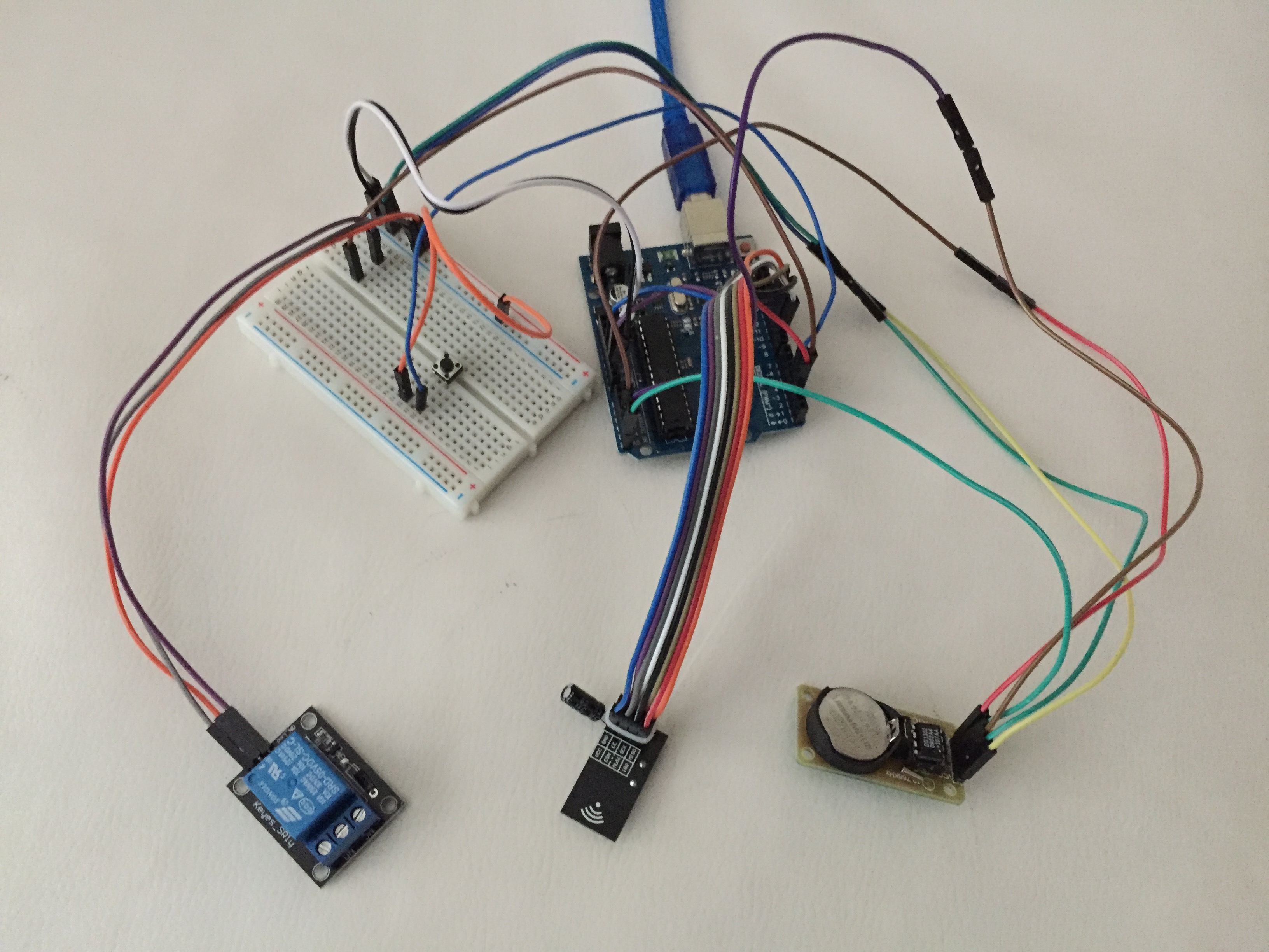
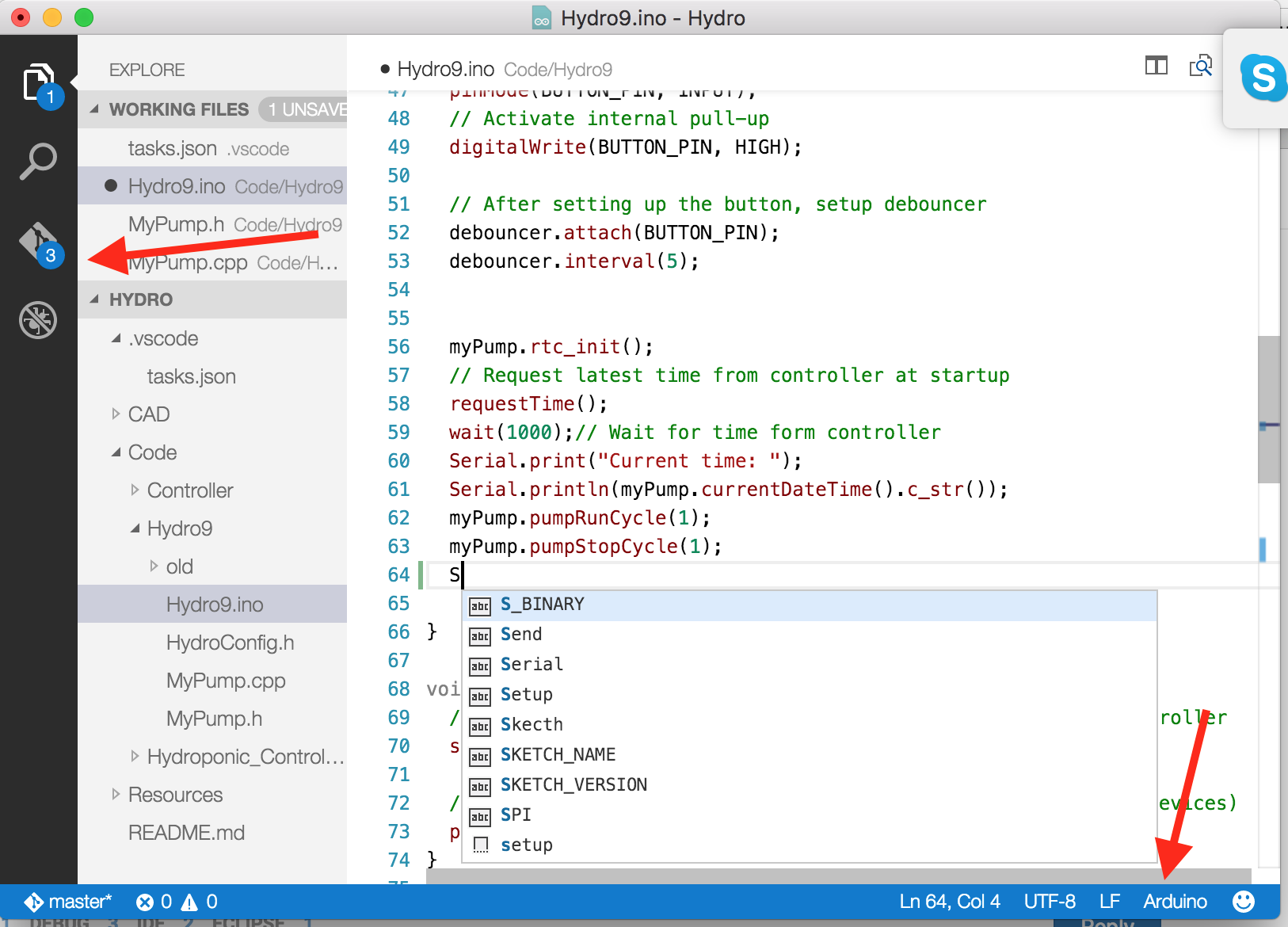
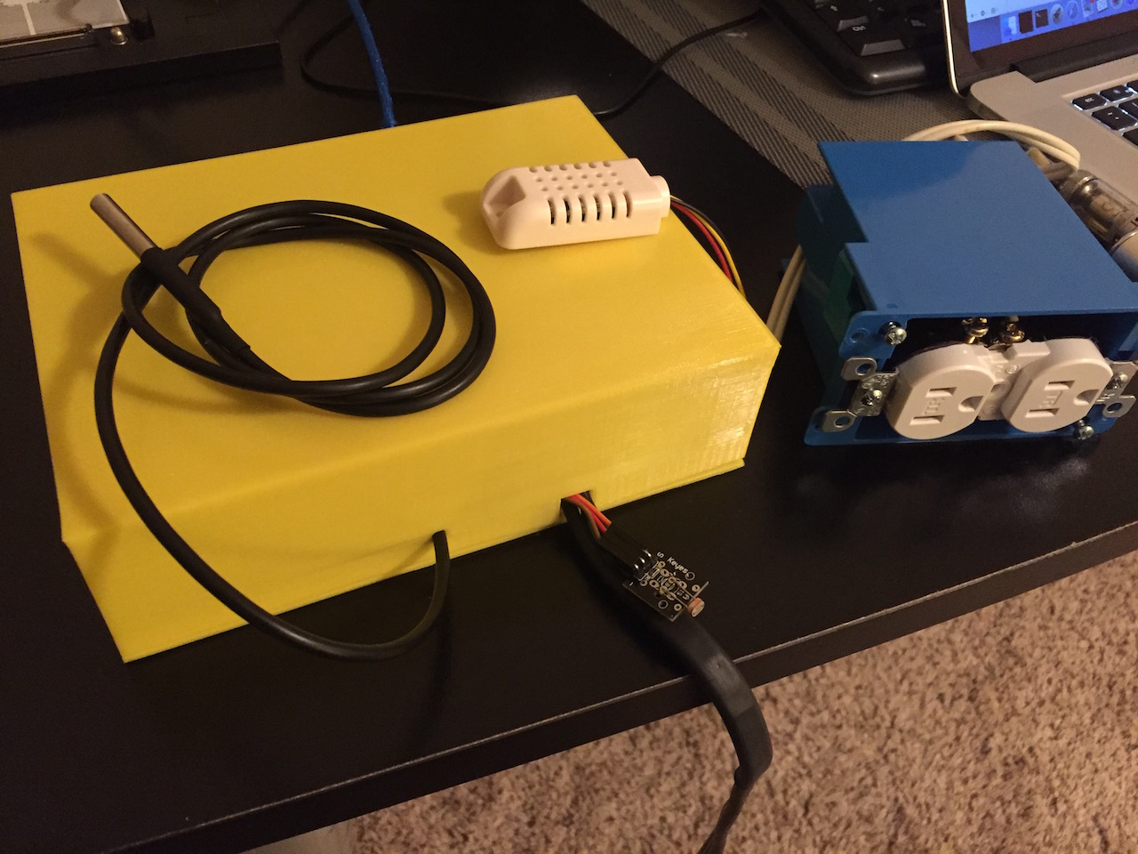
    I've finally finished with the software. Added a DHT22 for air temperature and humidity and also a Dallas for the water temperature.

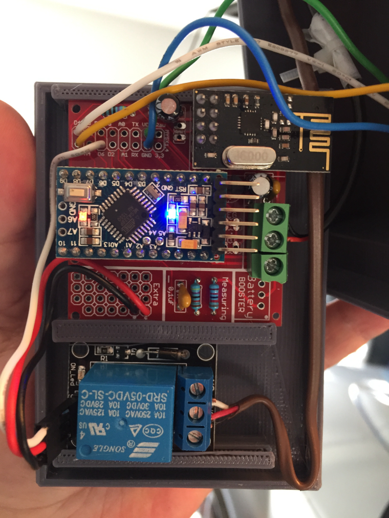
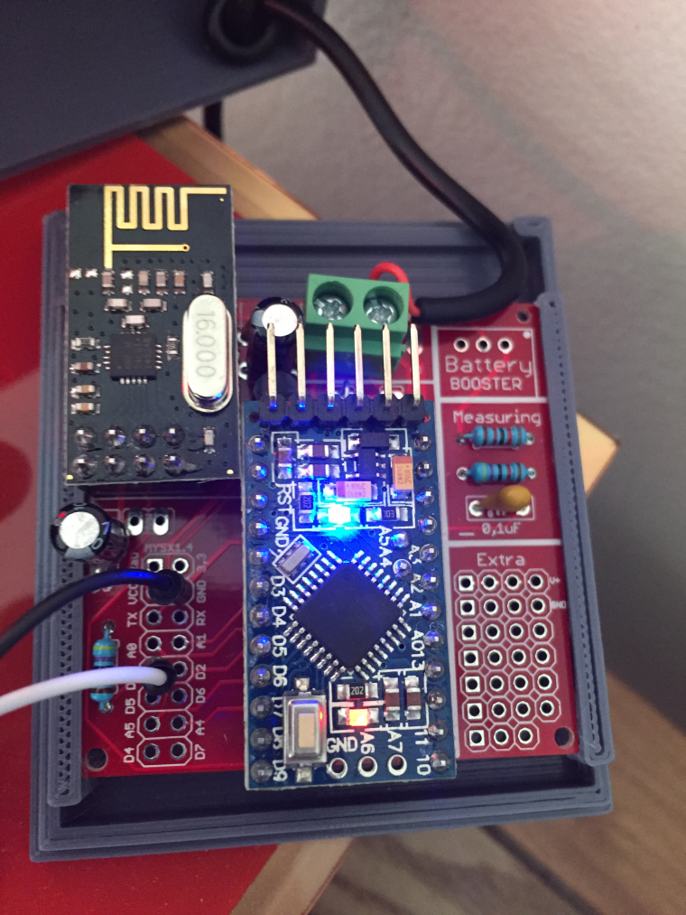
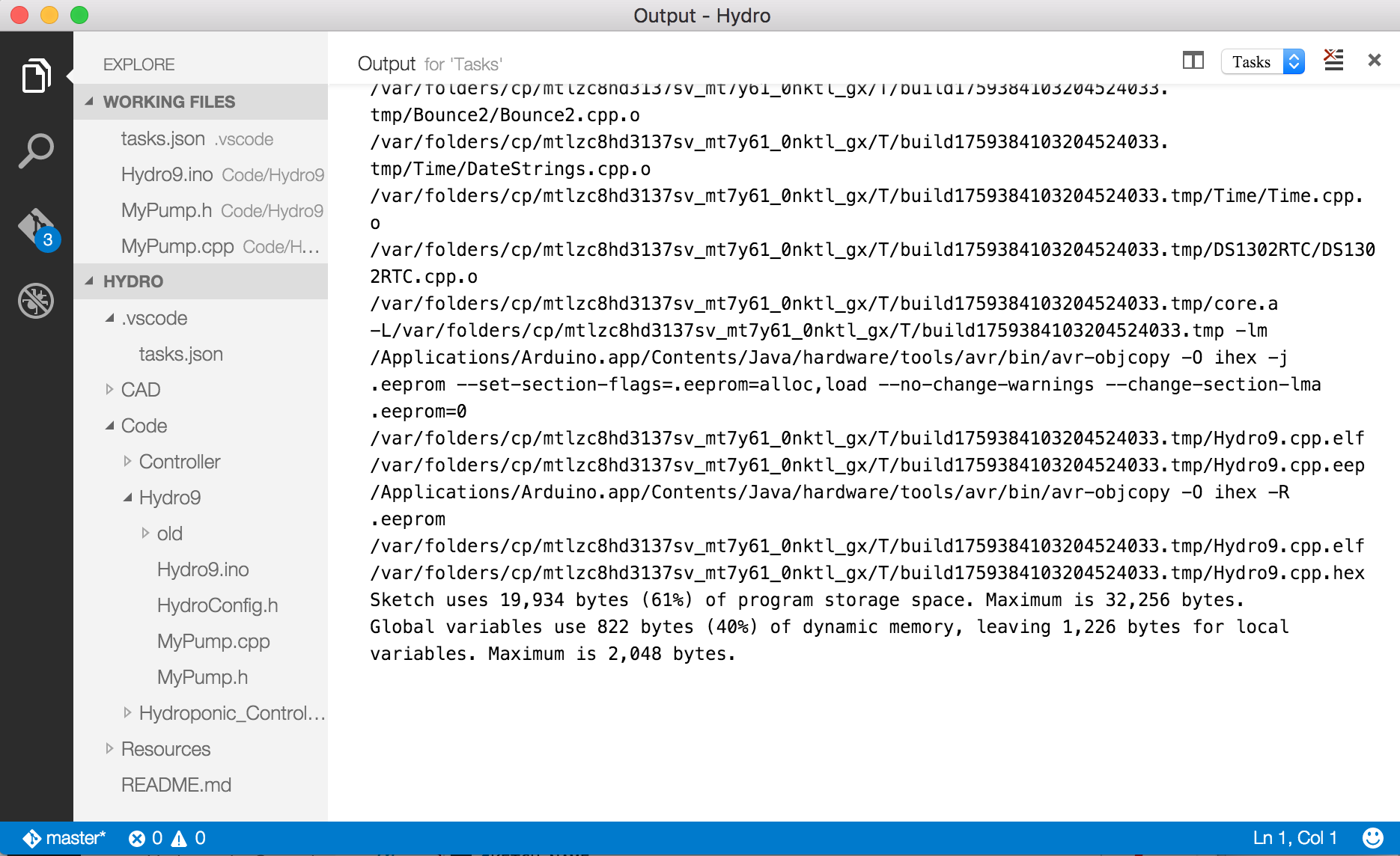
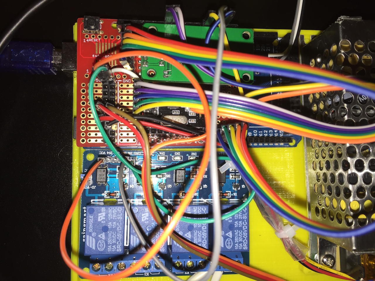
    Assembling the hardware was a bit more challenging then anticipated, but with no PCB, i've decided to use a proto shield and maintain support/flexibility for both UNO and MEGA boards. Soon after I've realized the code does not fit a UNO (too much debug eventually)

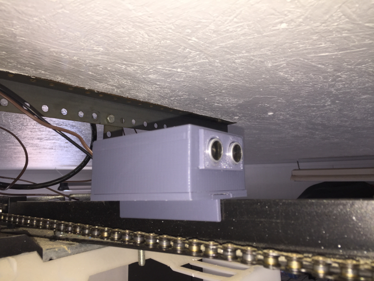
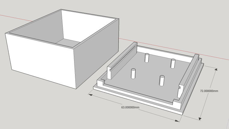
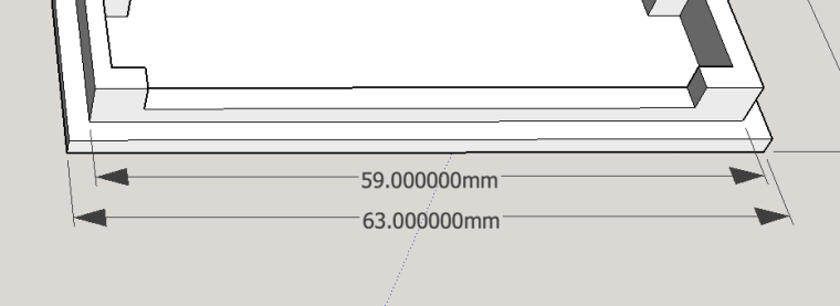
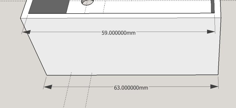
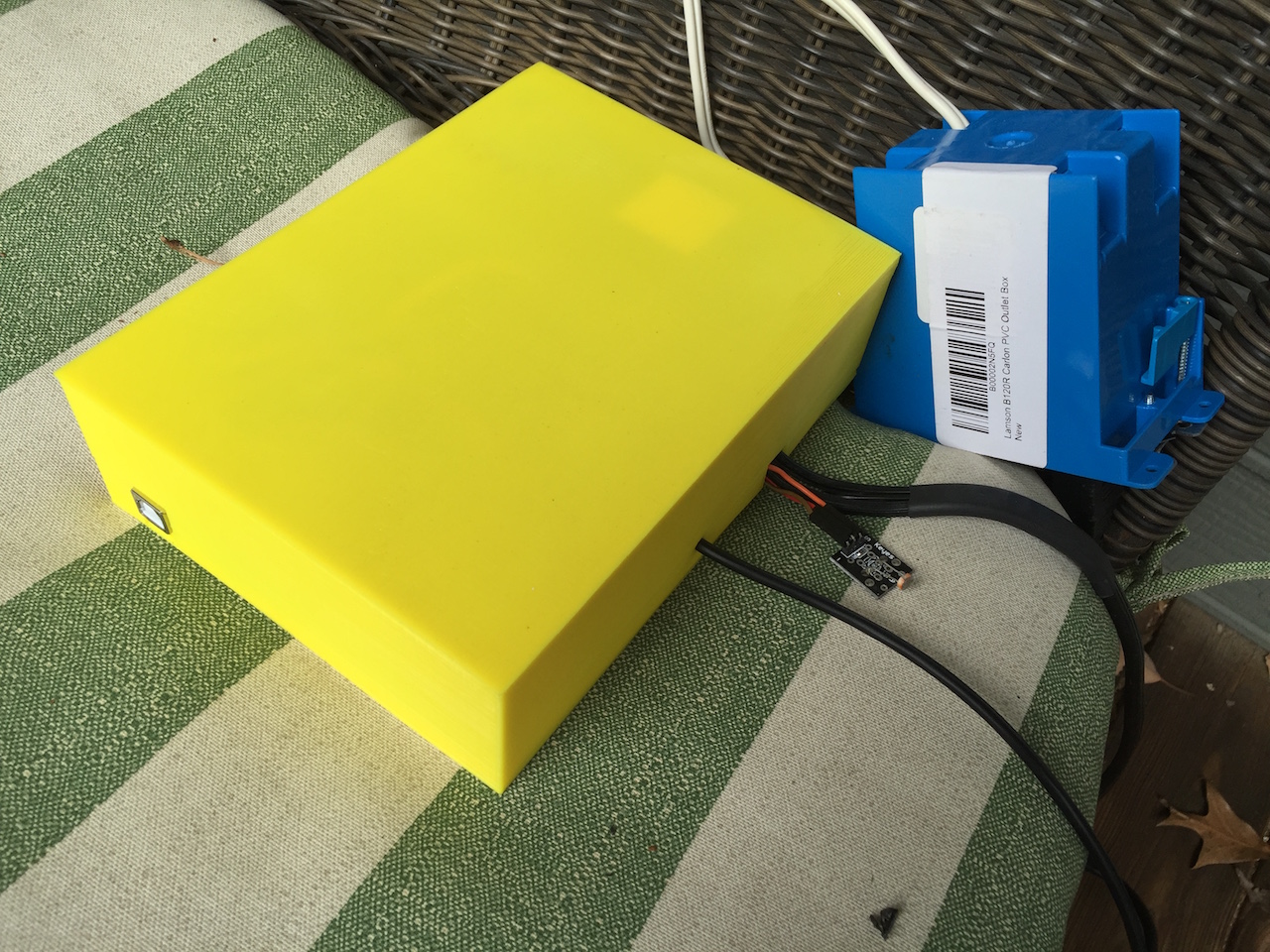
    Also created a simple case to enclose it all.
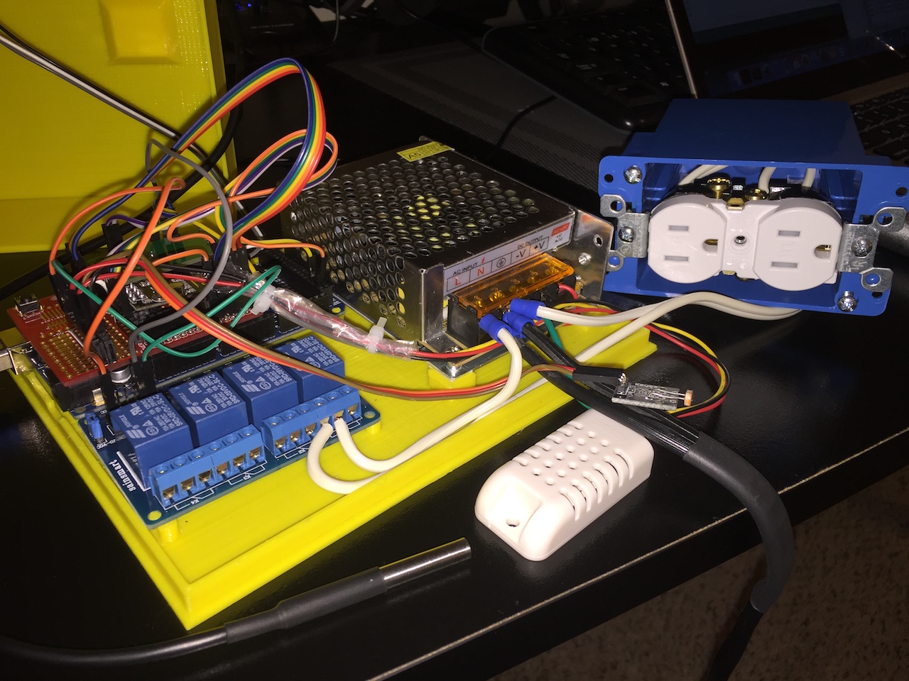
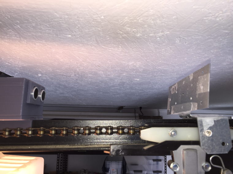
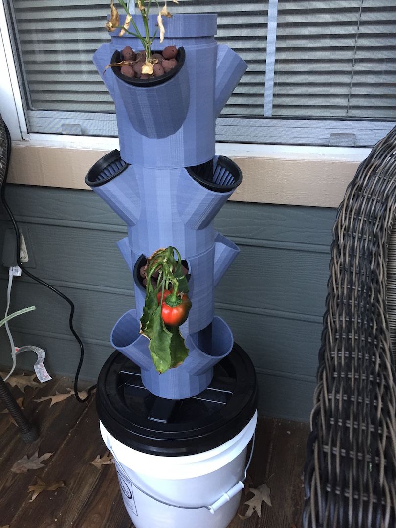
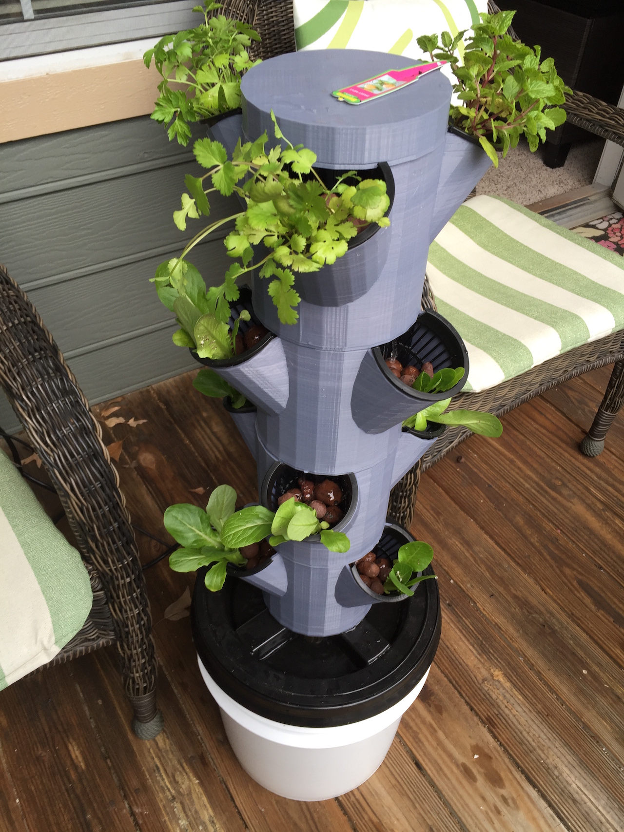
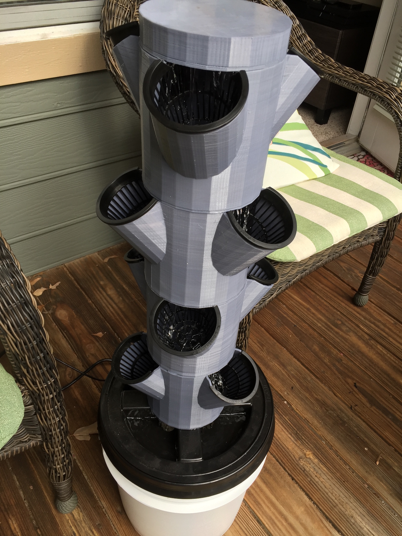
    0_1454265251361_IMG_0384.JPG

    0_1454265262066_IMG_0385.JPG

    0_1454265268911_IMG_0386.JPG

    The Column it self

    0_1454265463100_IMG_0390.JPG

    0_1454265475716_IMG_0392.JPG

    If anyone would likr to take a look at the code, feed back is much appreciated!

    Hydro9.zip

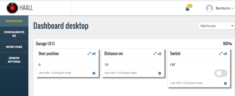
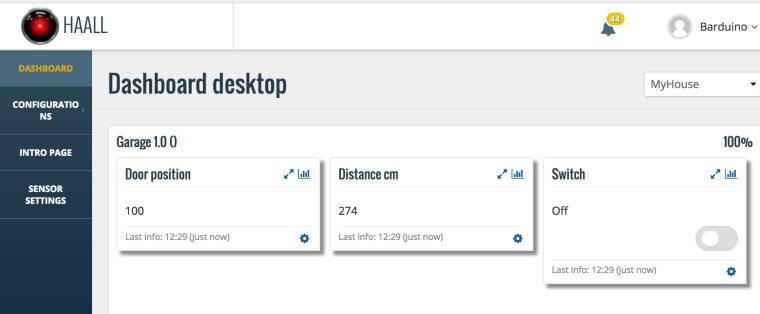
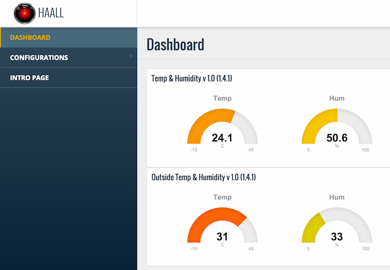
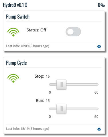
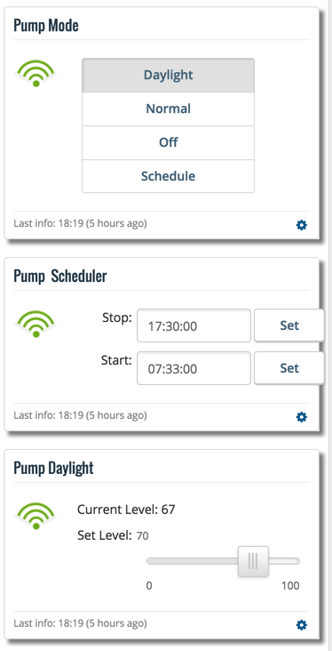
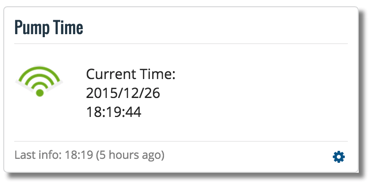
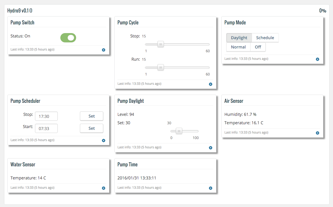
    Finally the dashboard looks like this

    0_1454265720134_upload-dbcd7b52-42f2-44ca-9290-b00e74d38e00

    Cheers

    EDIT: Forgot to add the startup log

    Starting sensor (RNNNA-, 1.6.0-beta)
    Radio init successful.
    Initializing DHT... Done!
    Dallas Temperature IC Control Library Demo
    Locating devices...Found 1 devices.
    Parasite power is: OFF
    Device 0 Address: 2817611D070000C3
    Device 0 Resolution: 9
    RTC module activated
    
    The DS1302 is write protected. This normal.
    
    RTC Sync TieStatus: 2 timeSet 2 Ok!
    send: 7-7-0-0 s=255,c=3,t=1,pt=0,l=0,sg=0,st=ok:
    read: 0-0-7 s=255,c=3,t=1,pt=0,l=10,sg=0:1454110229
    Time value received: 1454110229
    Pump Time:2016/01/29 23:30:28 
    send: 7-7-0-0 s=255,c=3,t=15,pt=1,l=1,sg=0,st=ok:0
    send: 7-7-0-0 s=255,c=0,t=17,pt=0,l=10,sg=0,st=ok:1.6.0-beta
    send: 7-7-0-0 s=255,c=3,t=6,pt=1,l=1,sg=0,st=ok:0
    read: 0-0-7 s=255,c=3,t=6,pt=0,l=1,sg=0:M
    Starting presentation
    send: 7-7-0-0 s=255,c=3,t=11,pt=0,l=6,sg=0,st=ok:Hydro9
    send: 7-7-0-0 s=255,c=3,t=12,pt=0,l=4,sg=0,st=ok:v0.1
    send: 7-7-0-0 s=1,c=0,t=3,pt=0,l=11,sg=0,st=ok:Pump Switch
    send: 7-7-0-0 s=2,c=0,t=23,pt=0,l=10,sg=0,st=ok:Pump Cycle
    send: 7-7-0-0 s=3,c=0,t=25,pt=0,l=9,sg=0,st=ok:Pump Mode
    send: 7-7-0-0 s=4,c=0,t=23,pt=0,l=14,sg=0,st=ok:Pump Scheduler
    send: 7-7-0-0 s=5,c=0,t=23,pt=0,l=13,sg=0,st=ok:Pump Daylight
    send: 7-7-0-0 s=6,c=0,t=6,pt=0,l=10,sg=0,st=ok:Air Sensor
    send: 7-7-0-0 s=7,c=0,t=6,pt=0,l=12,sg=0,st=ok:Water Sensor
    send: 7-7-0-0 s=10,c=0,t=23,pt=0,l=9,sg=0,st=ok:Pump Time
    End presentation
    Init complete, id=7, parent=0, distance=1
    **************** PUMP STATUS ***********************
    Pump Mode is:  Daylight
    Pump Cycle:    On:15 Off:15
    Pump Schedule: Start:07:33 Stop:17:30
    Pump Daylight: Start:70 Current:59
    Pump Time:     2016/01/29 23:30:34 
    ****************************************************
    ************* ENVIRONMENT STATUS *******************
    Air temperature:10.60 Air humidity:37.90
    Water temperature:10.00
    ****************************************************
    send: 7-7-0-0 s=1,c=1,t=2,pt=1,l=1,sg=0,st=ok:0
    send: 7-7-0-0 s=3,c=1,t=19,pt=2,l=2,sg=0,st=ok:3
    send: 7-7-0-0 s=4,c=1,t=24,pt=0,l=5,sg=0,st=ok:07:33
    send: 7-7-0-0 s=4,c=1,t=25,pt=0,l=5,sg=0,st=ok:17:30
    send: 7-7-0-0 s=5,c=1,t=37,pt=2,l=2,sg=0,st=ok:70
    send: 7-7-0-0 s=5,c=1,t=35,pt=2,l=2,sg=0,st=ok:59
    send: 7-7-0-0 s=2,c=1,t=37,pt=2,l=2,sg=0,st=ok:15
    send: 7-7-0-0 s=2,c=1,t=35,pt=2,l=2,sg=0,st=ok:15
    send: 7-7-0-0 s=10,c=1,t=24,pt=0,l=20,sg=0,st=ok:2016/01/29 23:30:34 
    send: 7-7-0-0 s=6,c=1,t=0,pt=7,l=5,sg=0,st=ok:10.6
    send: 7-7-0-0 s=6,c=1,t=1,pt=7,l=5,sg=0,st=ok:37.9
    send: 7-7-0-0 s=7,c=1,t=0,pt=7,l=5,sg=0,st=ok:10.0
    2016/01/29 23:30:34 Light level: 59
    
    My Project

  • Enclosure/Bumper for Easy/Newbie PCB
    barduinoB barduino

    @sundberg84 , absolutely, please do!
    Cheers

    Enclosures / 3D Printing

  • Hydroponics (Update 1/31) w/pics
    barduinoB barduino

    @samuel235

    Thanks for your enthusiastic support!!! :smiley:

    The reason for the big power supply is that I intend to have 2 solenoid valves to control the water flow, one to send water to the column the other to recirculate the water in the bucket (needed when adding nutrients or adjusting the PH). Those run on 12v and can consume some amps.

    The next step would be to add a water level sensor, I'll fry the pump if the water level drops to low.

    The most difficult parts to get are the PH sensor and the TPM/TDS sensor, not only expensive but most of then are not designed to be permanently submerged.

    In the long run I'm also planning for 3 peristaltic pumps to send nutrients, acidic solution and base solution to adjust PH and nutrients level. These often run on 12v.

    The idea of getting the electronics on the column is quite interesting. It would have to be on top since the rest of the column is not water tight. I would need to find some clever way to deal with the cables.

    Any way, I've just finished adding the plants. Not the ideal time to plant anything (its winter here) but the frost is gone and they say lettuce goes well with cold temperatures.
    This is what it looks like week 0. We'll see how it goes.

    0_1454274356245_IMG_0393.JPG

    Cheers

    My Project

  • Easy/Newbie PCB for MySensors
    barduinoB barduino

    @nunver your're right I need a more elegant solution for that wire, there was no particular reason to connect it on the other side.

    For the protection i'm thinking a daughter board with the diode and the 9v connector and then join it with angle connectors on the main.

    Cheers

    Hardware

  • Best IDE to use for MySensors projects
    barduinoB barduino

    HI

    I've been trying vs code

    It has GIT integration, Arduino file format and some auto complete.

    vs_code_A.png

    It is also capable of verifying and uploading the sketch

    vs_code_b.png

    Cheers

    Development atmel studio eclipse debug visualmicro ide

  • Enclosure/Bumper for Easy/Newbie PCB
    barduinoB barduino

    Hi @Samuel235 ,

    And it works fine, whatever the calibration error is, it's consistent.

    The base
    0_1490909222169_upload-cd8607af-cc5a-4aa7-9e5b-760b70a0c054

    The cover
    0_1490909239113_upload-71b58885-999b-4909-88e3-bf6b7bad9df5

    So in reality, the finished part size might not be exactly that, but whatever the difference is, it is propagated to both parts. This probably wouldn't be true if I printed the parts separately in different printers.

    Anyway, we're talking about tenths of millimeters.

    3D printer generically are very precise.

    Cheers

    Enclosures / 3D Printing

  • Hydroponics (Update 1/31) w/pics
    barduinoB barduino

    Hi folks,

    Quick update on my progress.

    I was wondering how other controllers could handle this situation.

    If anyone has some input I would appreciate the feedback.

    Here is how I split the nodes and messages.

    upload-9787f916-e061-497e-8fa6-f2138fc0ab58
    upload-3ae87651-8ac8-4d2f-b170-32844c86e61c
    upload-3d0617aa-9af5-4153-a21c-c3995deb6b7e

    Had to combine V_LEVEL with other messages such as V_VOLUME in order to have 2 similar messages on the same sensor.

    I wonder if "normal"controllers just treat one message one sensor?

    Cheers

    My Project

  • OpenHardware.io
    barduinoB barduino

    Fantastic idea

    Announcements

  • Freedomotic
    barduinoB barduino

    @freedomotic

    When you say you dont have hardware for testing, what do you mean?

    Do you have ate least 2 Arduinos?

    Im working on a way to simulate sensors, still alpha and not tested (im travelling) but so far it should be capable of simulating 12 sensors.

    Would this work for you?

    Freedomotic automation serialgateway controller

  • 2.0 beta, compatible with 1.5?
    barduinoB barduino

    @Erik-Forsberg

    I've been using beta and i'm very happy with it.

    If you do find problems, first update it again to get the newest builds and if the issue is still there report it.

    I'm sure folks will appreciate having another person testing.

    Cheers

    Development

  • Test your home made controller with MockMySensors (w/ tutorial)
    barduinoB barduino

    @akbooer

    That is correct.

    Also, because i'm having some issues updating the source code in git hub here is the latest version (lib 1.5) MockMySensors.ino and l(lib 1.4) FakeMySensorsOrig.ino

    Cheers

    Controllers

  • Building an Ethernet Gateway on an Arduino Mega
    barduinoB barduino

    I have a similar issue with Adafruit CC3000 shield and a Mega.
    After much fidling around I finally got it to work.

    The Adafruit shiled is the same size of an Uno but when connected to a Mega it doesn't get the SCK, MOSI and MISO from the 13,11,12 pins, it gets them from the central connector ICSP as showed on the picture on this thread.

    So first step was to connect the wireless module to the ICSP.

    The second issue is the CSN and CE pins, these can't be connected to 10 and 9 since they are used by the shield. I've used 35 and 34.

    Adjust your code like this:

    #define INCLUSION_MODE_TIME 1 // Number of minutes inclusion mode is enabled
    #define INCLUSION_MODE_PIN 32 // Digital pin used for inclusion mode button
    #define CE_PIN 35
    #define CS_PIN 34
    MyGateway gw(CE_PIN, CS_PIN, INCLUSION_MODE_TIME, INCLUSION_MODE_PIN, 6, 5, 4);

    Even with this, some times I still get a check wires message, others just a bunch of errors about the version.

    This erratic behaviour led me to think about noise on the wireless receiver, so in goes a 10uF.

    Its stable now.

    On a side note I also changed the CE and CS pin assignments on the sensors...

    #define DIGITAL_INPUT_SENSOR 4 // The digital input you attached your motion sensor. (Only 2 and 3 generates interrupt!)
    #define INTERRUPT DIGITAL_INPUT_SENSOR-2 // Usually the interrupt = pin -2 (on uno/nano anyway)
    #define CHILD_ID 1 // Id of the sensor child

    #define CE_PIN 9
    #define CS_PIN 53

    MySensor gw(CE_PIN,CS_PIN);

    // Initialize motion message
    MyMessage msg(CHILD_ID, V_TRIPPED);

    Cheers

    Troubleshooting

  • Visiting Sweden
    barduinoB barduino

    We expect pictures btw.... :smiley:

    General Discussion
  • Login

  • Don't have an account? Register

  • Login or register to search.
  • First post
    Last post
0
  • MySensors
  • OpenHardware.io
  • Categories
  • Recent
  • Tags
  • Popular