barduino
Posts
-
Garage door contraption (yet another) -
MQTT on Serial Gateway?Hi @Grubstake,
Not much else...
You can have node running (as a service or daemon) on any device that has a USB port (PC, mac, RPI) and it is agnostic of what controller you have.
Are you interested in the code details? Check the MySensors post I included in the link.
The MySensors typical messages is something like this 30;5;1;0;37;70
Which gets translated to /whateverpathyouwant/out/30/5/1/0/37 Payload: 70
And vice versa.
The reason I did this was because I had no WiFi or Network enabled gateway.
Cheers
-
MQTT on Serial Gateway?Hi @Grubstake
In my case, I just use a nodeJS script which reads from serial and publishes to mqtt. It also subscribes from mqtt and sends it to serial.
Pretty straight forward. For more details, look here.
Cheers
-
Enclosure/Bumper for Easy/Newbie PCBHi @Samuel235 ,
And it works fine, whatever the calibration error is, it's consistent.
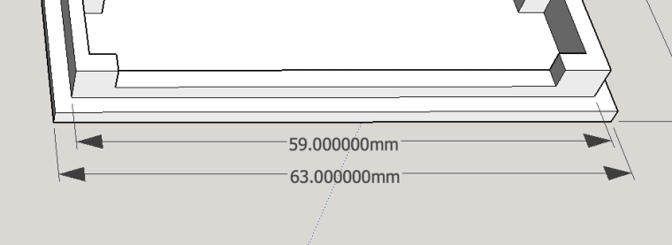
The base
The cover
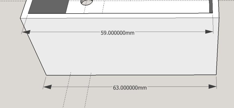
So in reality, the finished part size might not be exactly that, but whatever the difference is, it is propagated to both parts. This probably wouldn't be true if I printed the parts separately in different printers.
Anyway, we're talking about tenths of millimeters.
3D printer generically are very precise.
Cheers
-
Enclosure/Bumper for Easy/Newbie PCBHi @Samuel235 ,
It just snaps in. The lid sits on the first lip of the base. It's actually quite tight.
-
Garage door contraption (yet another)@dbemowsk , the problem is that I lost my screws... (portuguese joke meaning lost my marbles or gone crazy)
Anyway, do you create the threads for the screws in the plastic? or do you use self-threading...
When I do my supports I make them snap-on, like a little wider in the base and then a bit of plastic that goes through the board holes. If the holes are too thin the snap-on bit breaks.
cheers
-
Enclosure/Bumper for Easy/Newbie PCB@sundberg84 , absolutely, please do!
Cheers -
Garage door contraption (yet another)@dbemowsk, I'm very interested in your decora style wall plate, maybe we can compare notes
-
Enclosure/Bumper for Easy/Newbie PCBI'm not sure this is the best place to put this but here goes.
Here are some files to create a 3D printed box or bumper for the popular Easy PCV by @sundberg84
The STL file
0_1490735357002_EasyBoard_Base.stlthe SketchUp
0_1490735391058_GarageDoorMonitor.zip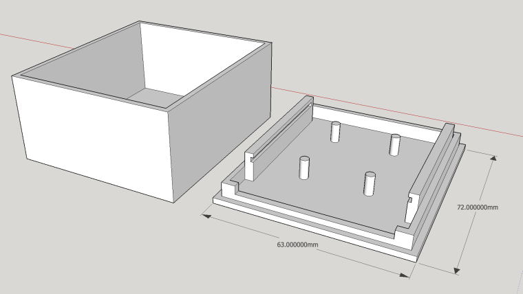
Have fun
-
Garage door contraption (yet another)Yeah, I wanted to know the exact position of the door, if it was opening or closing etc.
Anyway I'll gladly share the 3D files for the Easy board
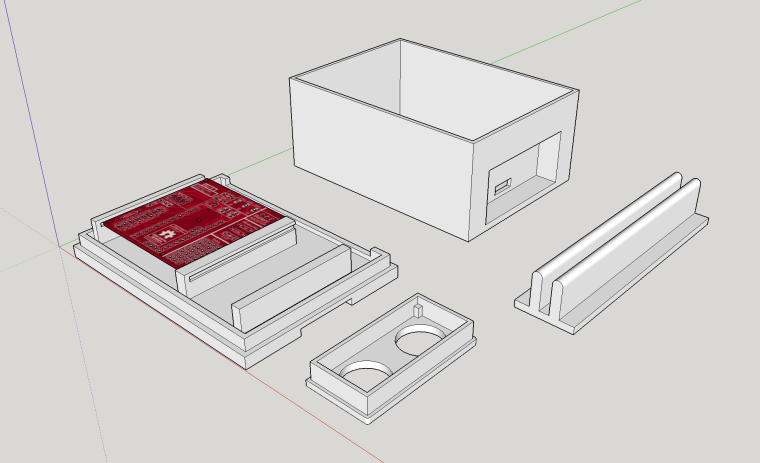
This is the SketchUp file with the base, rail, lid and enclosure for the sonic.
0_1490732828480_GarageDoorMonitor.zip
And this one the base and lid for the monitor.
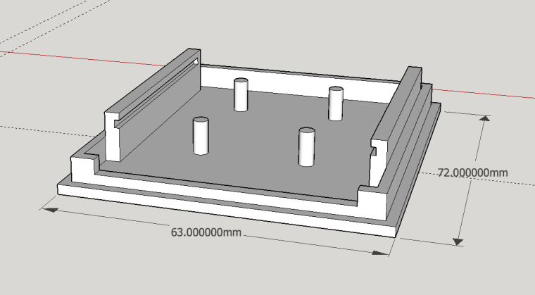
The Easy boards I have are v8 and the mounting holes are so small that I couldn't create a support that wouldn't break, so I decided to make some rail/slide system.
Also because I don't solder the Arduino or radio directly to the board, the lid becomes very tall. But its easy to adjust in the 3D files.
If you prefer STL files, I'll upload them
Cheers
-
Garage door contraption (yet another)Hi Folks
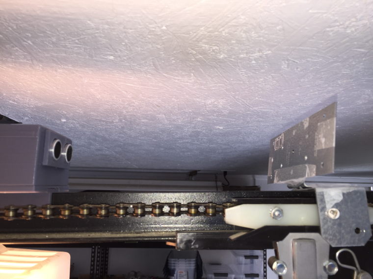
After leaving my garage door open all night for several times, I had to go ahead and make a MySensors contraptions for it.
The garage door system I have has 1 single button it will either open or close the door depending on position, the safety beams and the last operations.
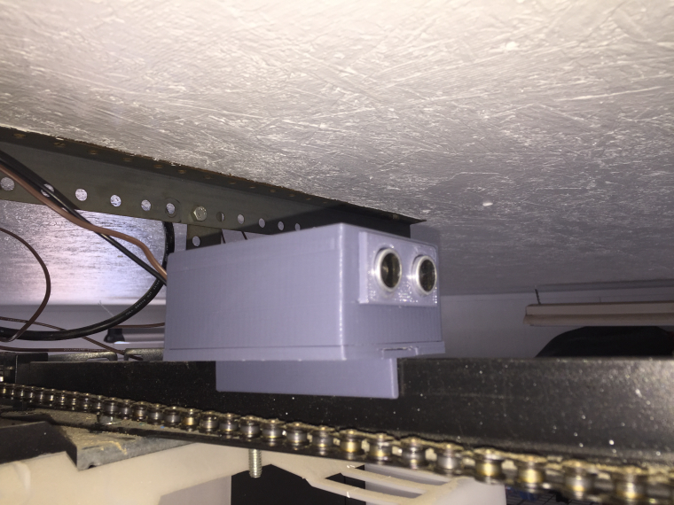
Since I know nothing about electronics, hacking the motor electronics was beyond my skill set, so I decide to sensorize the button operations. In order to figure out if the door was opening or closing I used a sonic distance relative to de door rail. I was expecting to have issues with precision but I was rather surprised it worked so well.
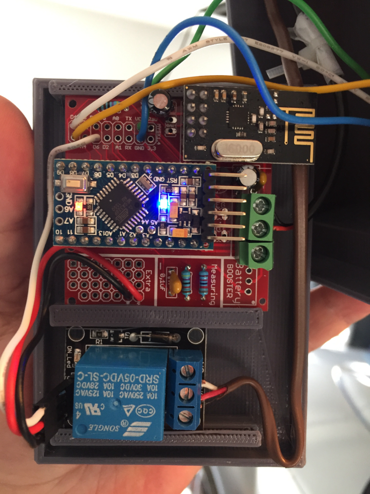
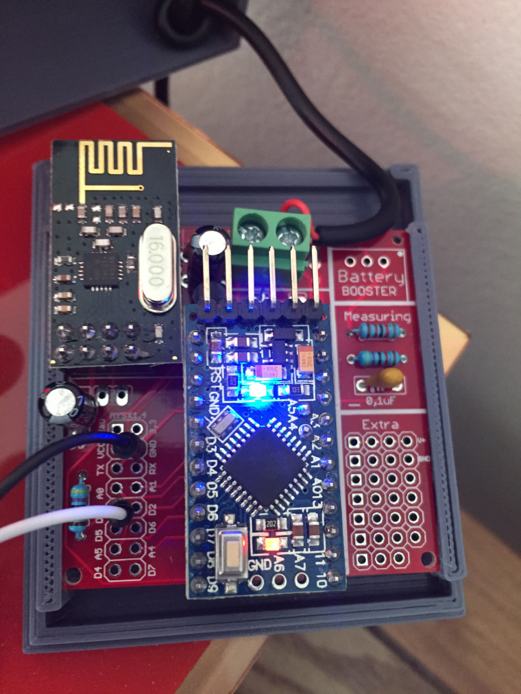
The base is the fantastic Easy/Newbie PCB for MySensors by @sundberg84 with a bumper/box of my own creation.
Coupled with some extra pieces as the rail support, the insert for the sonic sensor and the box lid it self.
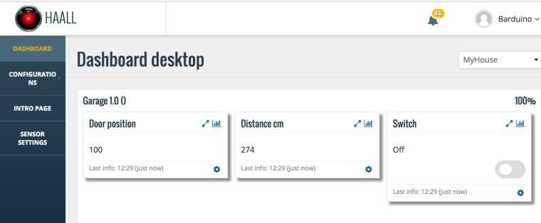
On the controller it looks like this
With door Open
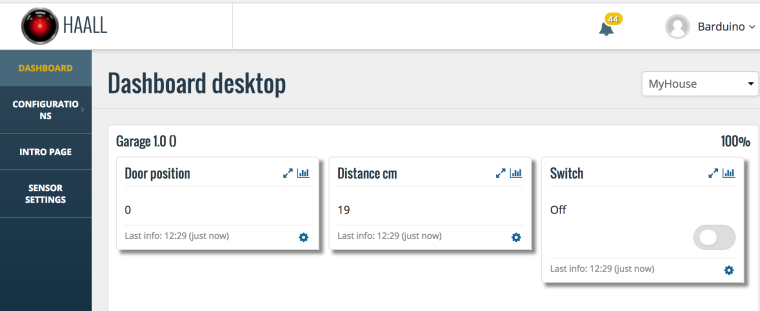
With door Closed
On the other side, I've created a simple led sensor which receives a door open/closed signal directly from the garage sensor to turn on or off a led.
As always feedback is appreciated
Cheers
-
Free MySensors 2.0 workshop, Friday 9 September in Amersfoort (The Netherlands) -
Free MySensors 2.0 workshop, Friday 9 September in Amersfoort (The Netherlands) -
Free MySensors 2.0 workshop, Friday 9 September in Amersfoort (The Netherlands)@Jason-Brunk
Where are you stationed? I'm in Atlanta, Georgia. Maker faire Atlanta is coming soon...
-
Free MySensors 2.0 workshop, Friday 9 September in Amersfoort (The Netherlands)What a great initiative!
If the video cant be recorded or shared I wonder if you would share some of the organizational details so it would make it easier to replicate this in other parts of the world.
Cheers
-
💬 MySensor Dioder (Ikea) -
💬 MySensor Dioder (Ikea)This is great.
I just got myself one of these Dioders
Could you detail the connections between arduino and the ikea board?
For example when you label AIN6 on the ikea board picture it connects to D6 in arduino?
- 3 for RGB (AIN6, AIN5, AIN4) - (D6, D5, D3)
- 3 for Buttons (OEN, AIN2, AIN3) - (D7, D4, D2)
- 1 ground
- 1 5v to arduino vin?
- 1 Color Wheel (AIN7 to Arduino A0)?
Is this correct?
-
Why is the the DIY PCBs on openhardware.io so expensive? -
"Weathercock" / weather comfort stationI dont know where you got the idea but is very accurate so to speak.
You can actually find a Weather Galo de Barcelos, its has some paint that changes color based on humidity.
Cool idea, cheers
-
"Weathercock" / weather comfort station