Skip to content
  • MySensors
  • OpenHardware.io
  • Categories
  • Recent
  • Tags
  • Popular
Skins
  • Light
  • Brite
  • Cerulean
  • Cosmo
  • Flatly
  • Journal
  • Litera
  • Lumen
  • Lux
  • Materia
  • Minty
  • Morph
  • Pulse
  • Sandstone
  • Simplex
  • Sketchy
  • Spacelab
  • United
  • Yeti
  • Zephyr
  • Dark
  • Cyborg
  • Darkly
  • Quartz
  • Slate
  • Solar
  • Superhero
  • Vapor

  • Default (No Skin)
  • No Skin
Collapse
Brand Logo
B

brolly759

@brolly759
About
Posts
53
Topics
4
Shares
0
Groups
0
Followers
0
Following
0

Posts

Recent Best Controversial

  • Low Power: How much current? [Solved]
    B brolly759

    @NeverDie I never had issues with Gammon's code on v1.6.5 . I had issues with the mysensors v1.4 library with v1.6.5 of Arduino IDE. My power problems went away when I switched to v1.5 of mysensors library. I have stopped troubleshooting for now as I am slightly burnt out but my last test on v.1.6.5 with v1.5 MySensors gave me strange results sometimes. If I edited any files in the sleep mode functions I would not be able to go back to sleep. I was draw a constant ~3mA.

    Congrats though and welcome to the club. I think I am going to just combine nRF Mesh + gammon's code to make my own mesh network setup. (When I actually know programming) ;)

    Hardware

  • Low Power: How much current? [Solved]
    B brolly759

    No idea why but every so often I have to uninstall Arduino, delete the libraries and basically start over. Getting frustrating and I might go back to 1.0.5 + v1.4 lib.

    Hardware

  • Low Power: How much current? [Solved]
    B brolly759

    Correct, I was able to use radio pin to shut it off (pin 4) manually in v1.4 library. I cant inject the code in v1.5. If I can put the code in the sleep function somewhere, it is not easy to find anymore.

    Hardware

  • Low Power: How much current? [Solved]
    B brolly759
    void RF24::powerDown(void)
    {
      ce(LOW); // Guarantee CE is low on powerDown
      write_register(CONFIG,read_register(CONFIG) & ~_BV(PWR_UP));
      digitalWrite(4, LOW);
    

    No matter where I put it... the NRF will not fall back asleep. It stays @ 4mA

    Hardware

  • Low Power: How much current? [Solved]
    B brolly759

    The new sleep library is all over the place and I cannot make heads or tails of it.

    I am using IDE 1.6.5 and MySensors v1.5 and I am getting 2uA in sleep mode with my modified BinarySensorSwitch sketch.

    I want to be able to shutdown the radio pin and LOW all the pins but I don't know where to add it. Anywhere I add, the radio stays high forever basically. Any idea's?

    Hardware

  • Low Power: How much current? [Solved]
    B brolly759

    I am using v1.6.5. I burned the bootloader for Pro Mini, still no change.
    Sleep mode: 17.9uA

    FYI, when upgrading from v1.4 to v1.5 of MySensors lib, DO NOT overwrite all the files, Delete the folder, add the new v1.5 I had a lot of errors just now

    I switched to v1.5 with v1.6.5 and I am getting 2uA in oState now. Now I am trying to play with the new sleep settings. will give an update soon.

    Hardware

  • Low Power: How much current? [Solved]
    B brolly759

    I just upgraded to Arduino IDE 1.6.5:

    Board: "Arduino Pro or Pro Mini"
    Processor: "Atmega328 (3.3V, 8MHz)

    Sleep current: 19uA.

    Using previous IDE I was @ 100nA.

    Here is the sketch I am using:

    #include <MySensor.h>
    #include <SPI.h>
    
    #define SKETCH_NAME "Binary Sensor"
    #define SKETCH_MAJOR_VER "1"
    #define SKETCH_MINOR_VER "0"
    
    #define PRIMARY_CHILD_ID 3
    #define SECONDARY_CHILD_ID 4
    
    #define PRIMARY_BUTTON_PIN 2   // Arduino Digital I/O pin for button/reed switch
    #define WIRELESS_POWER 4
    
    MySensor sensor_node;
    
    // Change to V_LIGHT if you use S_LIGHT in presentation below
    MyMessage msg(PRIMARY_CHILD_ID, V_TRIPPED);
    
    void setup()  
    {  
      pinMode(WIRELESS_POWER, OUTPUT);
      digitalWrite(WIRELESS_POWER, HIGH);  
      sensor_node.begin(); 
      pinMode(PRIMARY_BUTTON_PIN, INPUT);
     
       // Send the sketch version information to the gateway and Controller
      sensor_node.sendSketchInfo(SKETCH_NAME, SKETCH_MAJOR_VER"."SKETCH_MINOR_VER);
    
      // Register binary input sensor to sensor_node (they will be created as child devices)
      // You can use S_DOOR, S_MOTION or S_LIGHT here depending on your usage. 
      // If S_LIGHT is used, remember to update variable type you send in. See "msg" above.
      sensor_node.present(PRIMARY_CHILD_ID, S_DOOR);  
    }
    
    void loop() 
    {
      digitalWrite(WIRELESS_POWER, HIGH);
      delay(5);  
      sensor_node.begin();
        
      uint8_t value;
      static uint8_t sentValue=2;
    
      sensor_node.sleep(5);  
      value = digitalRead(PRIMARY_BUTTON_PIN);
      
      if (value != sentValue) {
         // Value has changed from last transmission, send the updated value
         sensor_node.send(msg.set(value==HIGH ? 1: 0));
         sentValue = value;
      }
    
      sensor_node.sleep(PRIMARY_BUTTON_PIN-2, CHANGE, 0);
    } 
    
    Hardware

  • Low Power: How much current? [Solved]
    B brolly759

    @NeverDie my 2 AA battery setup right now are @ 3.452v

    Hardware

  • Low Power: How much current? [Solved]
    B brolly759

    This is so frustrating, you know that?

    So I reseated my cables to make sure I am getting the best connection. Now my current is the last configuration is:

    sleep current oState: ~105nA
    sleep current cState: ~457nA

    @NeverDie my 2 AA battery setup right now are @ 3.452v

    Hardware

  • Low Power: How much current? [Solved]
    B brolly759

    @NeverDie Good catch, I just checked the version.h file. v1.4.1

    #define LIBRARY_VERSION "1.4.1"
    

    In the utilities folder in MySensors library, all the files like RF24.h, LowPower.h are provided by the MySensors library. So I am assuming they were up to date when the MySensors library was created.

    @scalz Even though its not full 3.3v it should be fine. The power range for NRF is 1.9v - 3.6v

    My next project is to figure out battery monitoring as low as possible. ;) I know there are 2 ways, internal 1.1v reference or voltage divider. Can I do a voltage divider on an output pin and shut the output pin off when not using it?

    Hardware

  • Low Power: How much current? [Solved]
    B brolly759

    OKAY so... more numbers to play with... This is Arduino turning on/off NRF using an output pin.

    • Connect Pin4 to VCC on NRF

    • Add SPI.end(); and for();loop to include Pin 4 to turn LOW in sleep function

    Add this code in define area:

    #define WIRELESS_POWER 4
    

    Add this code in loop():

    void loop() {
      digitalWrite(WIRELESS_POWER, HIGH);
      delay(5);  
      sensor_node.begin();
    

    Sleep current oState: .5uA - .6uA
    Sleep current cState: .8uA - .9uA

    @scalz Yes all my testing is on "binaryswitchsensor" sketch. I use the "DallasTempSensor" sketch when I want to test sleep() with a timer. There are SO MANY things you can do with a simple reed switch sensor. Doors, locks, windows, mailbox, fridge, cabinets, drawers... pretty much anything that moves and goes back in a certain place can be used with the "binaryswitchsensor".

    Hardware

  • Low Power: How much current? [Solved]
    B brolly759

    GOOD MORNING crazy tinkerer's. Okay here we go again, I am actually going to need someone to verify what I am looking at here, nA and uA are giving me different readings:

    Running the "for(); loop" in sleep() function with NRF VCC UNPLUGGED
    Sleep current: .8uA - .9uA OR 273nA

    Running the "for(); loop" in sleep() function with NRF VCC UNPLUGGED
    Sleep current: .6uA - .9uA OR 114nA

    @scalz I was powering the NRF directly from VCC. I will play around with connecting it directly to a pinOut on Arduino

    Hardware

  • Low Power: How much current? [Solved]
    B brolly759

    @Sparkman said:

    @brolly759 That's a different issue altogether. It's related to measuring battery voltage...

    Cheers
    Al

    tlund posted 2 months ago reply quote 0
    @tbowmo

    My NRF's are the same $1 nrf's listed in the mysensors store, so probably fake. But I have still measured them to draw ~900nA in powerDown.

    But I think I have found the culprint now. It seems the extra 20uA is caused by Arduino 1.6.5 (it may be that my installation is faulty).

    My test setup:

    pro mini
    nrf
    a simple sketch that does gw.sleep(60s)
    1st test: sketch compiled & uploaded via Arduino 1.0.5-r2: 6uA
    2nd test: sketch compiled & uploaded via Arduino 1.6.5: 24uA

    Hardware

  • Low Power: How much current? [Solved]
    B brolly759

    Someone else complained about the exact same issue here:
    http://forum.mysensors.org/topic/1345/sensebender-micro/250

    Hardware

  • Pro Micro Hookup and Code
    B brolly759

    Why dont you burn the bootloader using an Uno onto the nano? That way you can make sure its not a bootloader issue

    Hardware

  • Low Power: How much current? [Solved]
    B brolly759

    Running Arduino+NRF24l01 w/ interrupt consuming 1.5uA in sleep

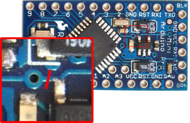
    I am using this Arduino Nano Pro 8mhz 3.3v :link text
    I am using this NRF chip: link text

    Here is my test environment:

    • Arduino Nano with desoldered jumper for bypassing voltage regulation (If you dont have bypass jumper on the knock off Nano, look at this post: link text )
    • NRF connected via pinout on MySensors guide
    • 3V direct supply from 2 AA Batteries
    • uCurrent Gold testing voltage current
    • Fluke 179 reading in mV
    • Using the BinarySwitchSensor sketch in the MySensors library

    If I upload the sketch as is with the recommended setup guide, Pin 2 or 3 is an interrupt pin and that goes to GND and acts as a switch. Pin 2/3 is HIGH and uses the internal pull up resistor. We will refer to the 2 different states of the switch as follows:

    "oState" (Open, when Pin 2/3 does NOT touch GND)
    "cState" (Closed, when Pin 2/3 touches GND)

    When running everything I get these sleep numbers:
    oState: 23-24uA
    cState: 117uA

    I downgraded my Arduino IDE from 1.6.5 to 1.0.6 and here are my new numbers:
    oState: 2.5-2.7uA
    cState: 98-100uA

    Everything is looking good but my cState is still too high for any battery applications that I am trying to get.

    Removed digitalWrite on pin 2/3. Connected 10M resistor from pin 2 to VCC. GND is switch to pin 2.
    oState: 2.5-2.7uA
    cState: 3.1-3.2uA

    Reference measurements:

    At this point I ran the "DallasTemperatureSensor" to test current using the WDT, I did NOT connect Temp sensor
    Sleep current with WDT enabled @ 30 seconds: 7.6-7.8uA

    Using "BinarySwitchSensor", remove NRF completely and only have Arduino:
    Sleep current: 110-120nA OR .4-.5uA (had issues reading this but I believe it is the nA)

    Connecting VCC/GND only to NRF to read standalone current:
    NRF only: 800-900nA Shutdown current

    Useless numbers while running the BinarySwitchSleepSensor sketch:
    Sleep current: 2.7-2.9uA with NRF/Arduino fully connected
    Sleep current with nRF GND disconnected: 1.7uA
    Sleep current with nRF VCC and GND disconnected: 294nA
    Sleep current with nRF VCC/GND/Pin9 disconnected: 281nA
    Sleep current with nRF VCC/GND/P9/P10 disconnected: 196nA
    Sleep current with nRF VCC/GND/P9/P10/P11/P12/P13 disconnected: 110-112nA
    Sleep mode with ONLY Arduino: 110-112nA
    NRF plugged into VCC/GND only: 800-900nA

    At this point we are getting 2.7-2.9uA with Arduino/NRF. Stock MySensors library and Arduino 1.0.6 IDE. ( I am using the BinarySwitchSleep Sketch from MySensors lib)

    To get even lower power....

    Open up mysensors.cpp with NotePad++ application
    Look for this code:

    bool MySensor::sleep(uint8_t interrupt, uint8_t mode, unsigned long ms) {
        // Let serial prints finish (debug, log etc)
        bool pinTriggeredWakeup = true;
        Serial.flush();
        RF24::powerDown();
        attachInterrupt(interrupt, wakeUp, mode);
        if (ms>0) {
            pinIntTrigger = 0;
            sleep(ms);
            if (0 == pinIntTrigger) {
                pinTriggeredWakeup = false;
            }
        } else {
            Serial.flush();     
            LowPower.powerDown(SLEEP_FOREVER, ADC_OFF, BOD_OFF);
        }
        detachInterrupt(interrupt);
        return pinTriggeredWakeup;
    }
    

    We are going to add this code:

    SPI.end();  
        for (byte i = 9; i <= 13; i++)
        {
        pinMode (i, OUTPUT);    
        digitalWrite (i, LOW); 
        }  // end of for loop
    

    The final code should look like this:

    bool MySensor::sleep(uint8_t interrupt, uint8_t mode, unsigned long ms) {
        // Let serial prints finish (debug, log etc)
        bool pinTriggeredWakeup = true;
        Serial.flush();
        RF24::powerDown();
        attachInterrupt(interrupt, wakeUp, mode);
        
        SPI.end();
        
        for (byte i = 9; i <= 13; i++)
        {
        pinMode (i, OUTPUT);    
        digitalWrite (i, LOW); 
        }  // end of for loop
    
        if (ms>0) {
            pinIntTrigger = 0;
            sleep(ms);
            if (0 == pinIntTrigger) {
                pinTriggeredWakeup = false;
            }
        } else {
            Serial.flush();     
            LowPower.powerDown(SLEEP_FOREVER, ADC_OFF, BOD_OFF);
        }
        detachInterrupt(interrupt);
        return pinTriggeredWakeup;
    }
    

    IMPORTANT: Because you are ending SPI, you will need to call the sensor at the beginning of your loop to reinitialize the NRF

    void loop() 
    {  
      sensor_node.begin();
    

    Adding both SPI.end(); and for(); loop:
    Sleep current: 1.5uA

    If you add just the SPI.end();
    Sleep current: 2uA

    If you just add the for(); loop:
    Sleep current: 1.9uA - 2.2uA

    • If you are using ONLY the "for(); loop", you do NOT need to reinitialize the radio when you come out of sleep. I have noticed a much longer up time when having to reinitialize.

    OTHER MEASUREMENTS using the DallasTemperatureSensor with WDT at 30 seconds, no sensor connected:

    Edited Sleep with for(); loop:
    Sleep current: 6.4-6.5uA

    Edited Sleep with for(); loop AND SPI.end();:
    Sleep current: (Could not get SPI.end(); to work on sleep(w/WDT))

    Quick comment: There are a few sleep options in the MySensors.cpp Depending on which one you are calling will depend on which one you need to edit. Here are some examples of the sleep functions in the .cpp file:

    void MySensor::sleep(unsigned long ms)
    
    bool MySensor::sleep(uint8_t interrupt, uint8_t mode, unsigned long ms)
    
    int8_t MySensor::sleep(uint8_t interrupt1, uint8_t mode1, uint8_t interrupt2, uint8_t mode2, unsigned long ms)
    
    Hardware

  • Low Power: How much current? [Solved]
    B brolly759

    I keep watching you edit your post, its freakin me out! lol

    Hardware

  • Low Power: How much current? [Solved]
    B brolly759

    I have an O-scope just dont know how to use it completely lol. Leaving work now. Stayed extra 2 hours to play with power settings lol

    @NeverDie did you still need me to write up what I did or you followed it pretty much?

    Hardware

  • Low Power: How much current? [Solved]
    B brolly759

    Some more facts here:

    If you ONLY do the for/loop to shut off PIN9-13 in the sleep function and do NOT shut off SPI... you do NOT need to reinitialize the radio on wake-up.

    The current draw for For/Loop LOW w/o shutting off SPI is 2.1uA-2.2uA.

    This is a good and bad. If you have a sensor that is going to be switched on and off a lot, the re initialization time is noticeable on a fluke meter. You can see it staying high much longer. So, if someone knows how long it takes to initialize, then we can determine if shutting off SPI is worth it. ~600nA savings vs high reconnect time.

    Hardware

  • Low Power: How much current? [Solved]
    B brolly759

    Okay, so originally I was getting 2.7-2.9uA with Arduino/NRF. Stock MySensors library and Arduino 1.0.6 IDE. ( I am using the BinarySwitchSleep Sketch from MySensors lib)

    To get even lower power.... If you open up mysensors.cpp the sleep function is there. For the BinarySwitchSleep sketch you are looking for this sleep function as there are a few:

    You want to add this:

    SPI.end();	
    	for (byte i = 9; i <= 13; i++)
        {
        pinMode (i, OUTPUT);    
        digitalWrite (i, LOW); 
        }  // end of for loop
    

    to this:

    bool MySensor::sleep(uint8_t interrupt, uint8_t mode, unsigned long ms) {
    	// Let serial prints finish (debug, log etc)
    	bool pinTriggeredWakeup = true;
    	Serial.flush();
    	RF24::powerDown();
    	attachInterrupt(interrupt, wakeUp, mode);
    	if (ms>0) {
    		pinIntTrigger = 0;
    		sleep(ms);
    		if (0 == pinIntTrigger) {
    			pinTriggeredWakeup = false;
    		}
    	} else {
    		Serial.flush();		
    		LowPower.powerDown(SLEEP_FOREVER, ADC_OFF, BOD_OFF);
    	}
    	detachInterrupt(interrupt);
    	return pinTriggeredWakeup;
    }
    

    and it will look like this:

    bool MySensor::sleep(uint8_t interrupt, uint8_t mode, unsigned long ms) {
    	// Let serial prints finish (debug, log etc)
    	bool pinTriggeredWakeup = true;
    	Serial.flush();
    	RF24::powerDown();
    	attachInterrupt(interrupt, wakeUp, mode);
    	
    	SPI.end();
    	
    	for (byte i = 9; i <= 13; i++)
        {
        pinMode (i, OUTPUT);    
        digitalWrite (i, LOW); 
        }  // end of for loop
    
    	if (ms>0) {
    		pinIntTrigger = 0;
    		sleep(ms);
    		if (0 == pinIntTrigger) {
    			pinTriggeredWakeup = false;
    		}
    	} else {
    		Serial.flush();		
    		LowPower.powerDown(SLEEP_FOREVER, ADC_OFF, BOD_OFF);
    	}
    	detachInterrupt(interrupt);
    	return pinTriggeredWakeup;
    }
    

    Because you are shutting off and turning all pins low, you will need to add this to the beginning of your program loop to reinitialize the NRF:

    void loop() 
    {  
      sensor_node.begin();
    

    If you add just the SPI.end(); your current will be 2uA.
    If you add both SPI.end(); and LOW pin loop, your current will be 1.5uA

    Hardware
  • Login

  • Don't have an account? Register

  • Login or register to search.
  • First post
    Last post
0
  • MySensors
  • OpenHardware.io
  • Categories
  • Recent
  • Tags
  • Popular