@gohan for me version dev (2.2)
Carl H
@Carl H
Posts
-
💬 Building a Raspberry Pi Gateway -
💬 Building a Raspberry Pi GatewaySame trouble for me. I use mySensors since 2 years and I have no problem with my Arduino Gateway. But from now 2 weeks, I try to use a pi gateway. It's working well but sometime, don't no why, my nrf24 stop to receive messages. Just restarting mygw service and re-work again. I don't see nothing anormal in my log, stop randomlly after 1 or 2 days.
Maybe a power issue to nrf24, I will try to add capacitor just for testing if can resolve this problem.
-
💬 Very narrow and minimal switch node@GertSanders Thanks... after practice and practice and practice again... I have now 4 narrow board working with si7021 sensor... I need to put my solder tip very high and use alot of flux.. :)
-
💬 Very narrow and minimal switch node@GertSanders Yes I used the version 1.1 and yes I connect the jumper pad correctly.
After some hard test, I found the problem, is it my solder or a bad batch of SMD NRF24L01 :( I explain my problem, I make a good solder of the SMD NRF24L01, I put power on the board for testing it and is it working for 2-3 loop because I open the led (d6) on each loop. After 2-3 loop the board is freezing. After I check again the solder and some pin of the SMD NRF24L01+ is shorted (check with my multi-meter). I can explain why, is it my skill of soldering or a bad batch of SMD NRF24lL01+. I test with 5 different and always the same, after power it.. it will shorted some pin. I make my order on this ebay store: http://www.ebay.ca/itm/401054727893?_trksid=p2057872.m2749.l2649&ssPageName=STRK%3AMEBIDX%3AIT
-
💬 Very narrow and minimal switch node@alexsh1 I use the this lib: https://github.com/LowPowerLab/SI7021 My board freeze when initialize with begin function.
I can't have the error exactly because this board don't have any FTDI connection. But the same atmega328p chip with other board, it's working !! I think again is it because the board use internal oscillator.
-
💬 Very narrow and minimal switch nodeHi, I have finally receive your narrow board.. I try with a Si7021 sensor (the GY-21 ebay version) and I have no success. But with your other board, because I have your 2 other board version (ac/dc board and the small battery one) it's working with no problem. The difference I think is the first board without external crystal. After reading in forum, I think with Slim board version, i'm not the first with this problem. Did you test your board with si7021 sensor, or can you give my a clue ?? Thanks
-
💬 AC/DC/Batteries capable atmega328p board@GertSanders oh thanks, I have made an error... Maybe it will be working with MYSBootloader 1.3pre2 because he don't require any external memory.. Did you try before?
-
💬 AC/DC/Batteries capable atmega328p board@GertSanders I have a couple of your board and I will be very happy. Now I will want to try the OTA feature with this board. Did you have DualOptiboot already compiled (hex file) with D8 led pin and with 8 mhz external crystal? It will be cool you include this file like Optiboot 6.2.. Thanks
-
💬 AC/DC/Batteries capable atmega328p boardAfter make some test this morning I found a solution but I do not know why and what is the difference.
I explain:
When I used this DHT librairies (https://github.com/markruys/arduino-DHT), this one come with mysensors librairies. I can read my DHT22 sensor with my FTDI cable but is not working with from a DC 5v in, reading always 0.
But If now I used this librairies (https://github.com/adafruit/DHT-sensor-library) , is working with FTDI cable and now with my DC 5v in.
-
💬 AC/DC/Batteries capable atmega328p board -
💬 AC/DC/Batteries capable atmega328p board -
💬 AC/DC/Batteries capable atmega328p boardThis is my board:
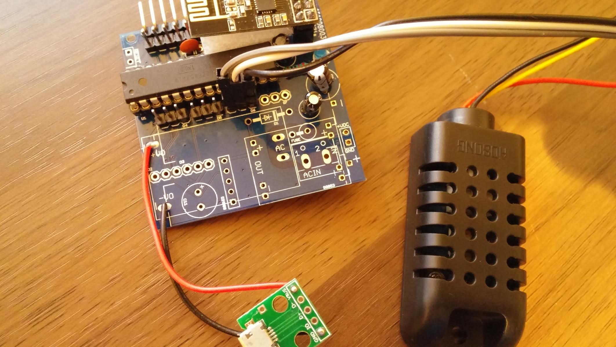
I don't want to use the bat jumber because my source is by USB plug (5v).
My question is why is it working when I plug with my FTDI Cable (5v version).
I will try tonight with other sensor like Si7021 but i'm pretty sure it will be working.
-
💬 AC/DC/Batteries capable atmega328p board@GertSanders Can you give me a hint? I have 10 of this board and for one I want to use with external DC 5v. For this one, I put the AMS1117. All is working when I check with my meter, I have 3.3v for the NRF24 and 5v for the ATMEGA328P. Now when I use this board with DHT22 temp sensor (plug into D7), I check my scketch with FTDI cable and the Serial Monitor of Arduino IDE and all is working good. When I used with the external DC 5v, all the board working good except the DTH22, read 0 for temp and humidity but NRF24 work good. I try to figure what is the problem and I can't find any solution. My external DC is pluged into same terminals as the battery holders V+ and V-.
Thanks again and sorry for my skill of english, I'm french from Quebec, Canada.
-
💬 Very narrow and minimal switch node@GertSanders , 1 question, you have specified 1/8w resistor... did you know if 1/4w fit on narrow board ?
-
💬 Very narrow and minimal switch node@GertSanders I'm a fan of your boards. I have your 20x30mm board, AC/Capable 50x50mm board (my favorite) and now I ordered your v1.1 of your narrow board because you are agree my suggestion for I2C port with jumper ;)
-
SI7021 boardsYour plan is it to change your narrow board with SDL/SDA pad. maybe a jumper to change D2/D3 pin to SDL/SDA?
-
My own board (50mm x 30mm) -
My own board (50mm x 30mm)Hi GertSanders,
After ordered and make 3 of 50mm x 30mm board with success. Now I ordered the AC Capable 50mm x 50mm board. I try to read the schema and I have some question. If I want to use this board with only 2 AAA battery, Do I need to use AMS1117? and witch jumper do I need to close? It is optional to use AT24C ?
Thank you for your help
-
My own board (50mm x 30mm) -
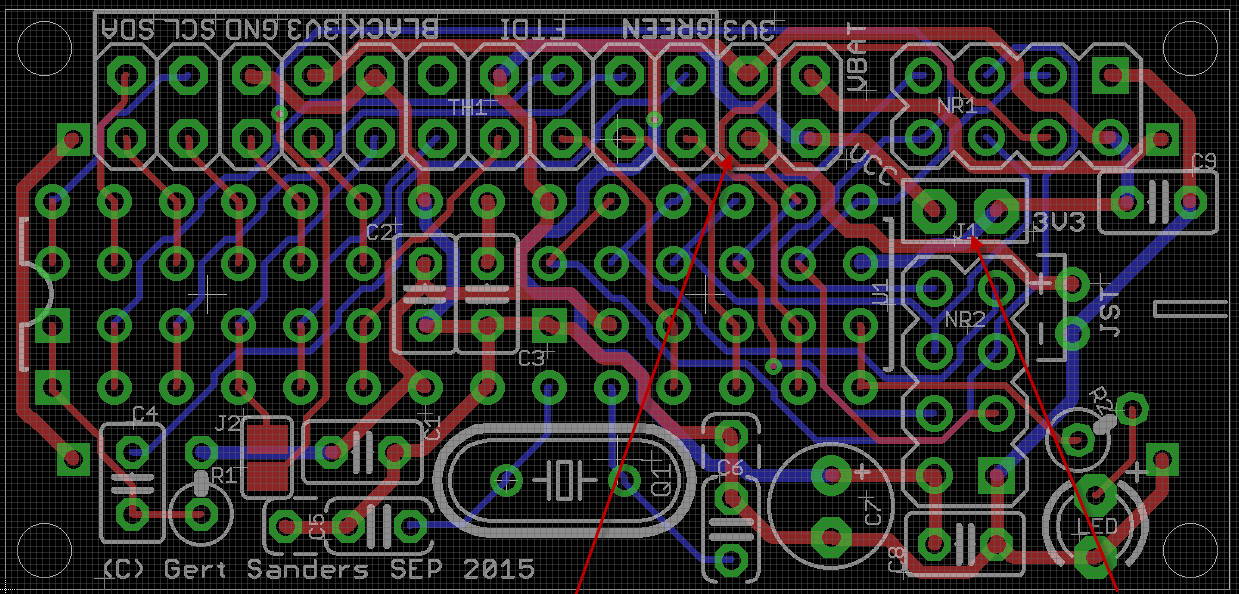
My own board (50mm x 30mm)I order from OSHpark the v2 of your own board and I have a question, if I run it with 2AA battery for example, I put jumpers (marked red on the picture) and it is working.
But if I want to try with 5v input, like from usb charger, do I need to have a 3.3v regulator for the NRF24+ ? And if yes, do I need other pcb to complete this?
Other question, what is the use of the jumper J1? I'm not sure...
Thanks again !!