Skip to content
  • OpenHardware.io
  • Categories
  • Recent
  • Tags
  • Popular
Skins
  • Light
  • Brite
  • Cerulean
  • Cosmo
  • Flatly
  • Journal
  • Litera
  • Lumen
  • Lux
  • Materia
  • Minty
  • Morph
  • Pulse
  • Sandstone
  • Simplex
  • Sketchy
  • Spacelab
  • United
  • Yeti
  • Zephyr
  • Dark
  • Cyborg
  • Darkly
  • Quartz
  • Slate
  • Solar
  • Superhero
  • Vapor

  • Default (No Skin)
  • No Skin
Collapse
Brand Logo
Dan S.D

Dan S.

@Dan S.
Hero Member
  • Getting Started
  • Controller
  • Build
  • Hardware
  • Download/API
  • Forum
  • Store
About
Posts
173
Topics
12
Shares
0
Groups
1
Followers
1
Following
0

Posts

Recent Best Controversial

  • Parking Sensor
    Dan S.D Dan S.

    Had some issues with the operation of my parking sensor which I resolved and now it seems to be working perfectly.
    Thought I would pass on what I did in the hope that it might help others having the same problem.

    There were 2 issues.

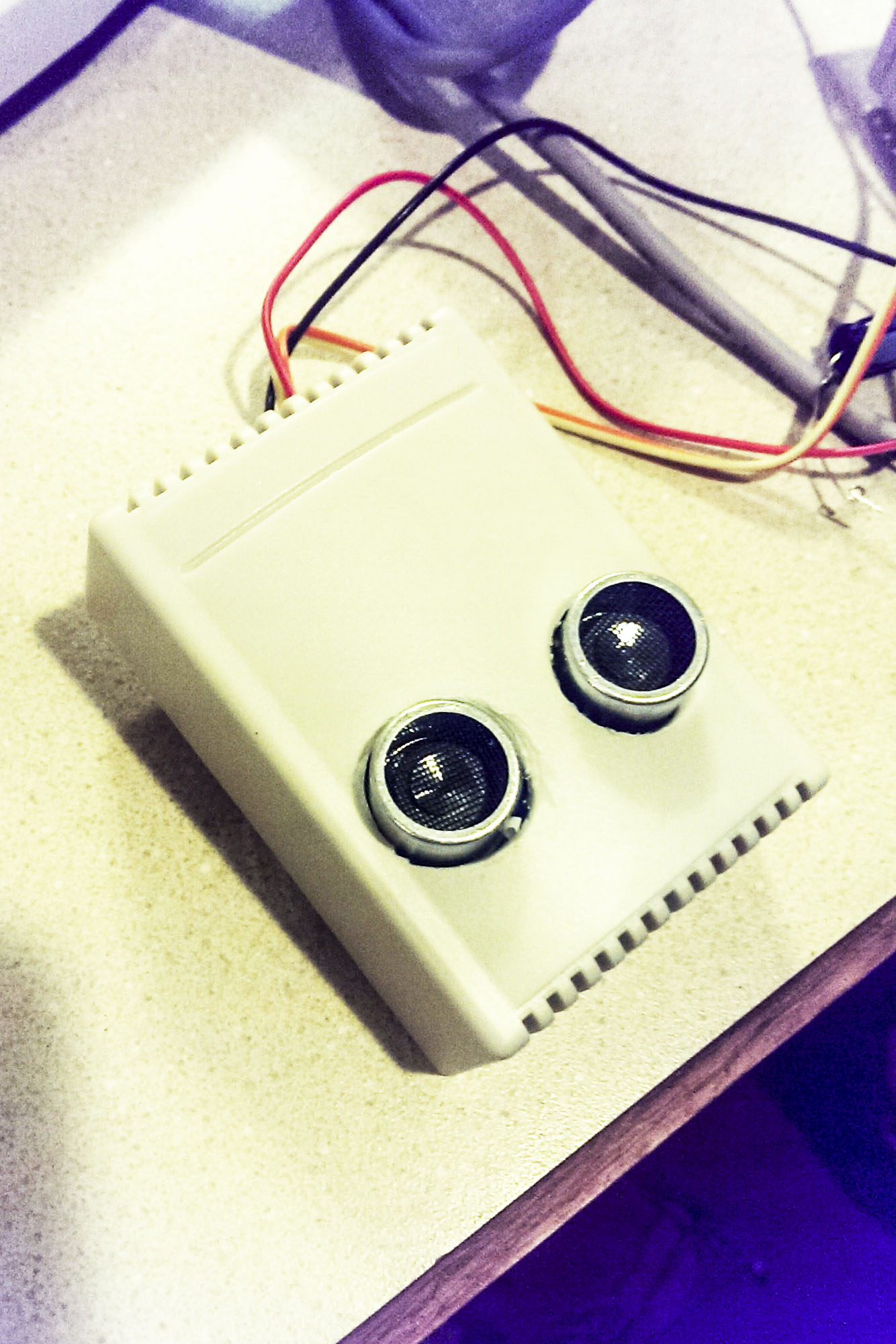
    The first issue was random lighting of the led ring after the car was pulled out of the garage and the door was closed. My guess was that the sensor, in the absence of having the solid car to bounce off of, was picking up stray sensor ping echoes from other objects in the garage. Checking on internet revealed that others using the HC-SR04 Distance sensor had experienced this problem. Checking further, I discovered that there were updates to the NewPing library, the latest being version V1.7 and specifically that V1.6 included an update to the sonar.ping_median function used for distance measurement in the parking sensor code. The MySensors library current version is V1.5. After I updated to V1.7 I no longer had random readings when the car was not in the garage. First problem solved.
    bolded textSo I would recommend updating to NewPing V1.7.

    I then reinstalled the parking sensor in the garage for further testing. Everything appeared to be going well but when I returned to park my car in the garage later in the day I was greeting by the led ring flashing bright red with all its leds which is supposed to be a panic signal that the car was parked as close as it should be. But I had just entered the garage and was not anywhere near the range of being parked. Took the sensor down and brought it in for testing. Found out that everything worked fine except if it was left on in the condition where it was not sensing any object in range for an extended period of time, it went into the flashing led mode. Too me it had the symptom that given enough time, a variable was being overrun (an integer variable exceeding its capacity). Checking over the code I noted the following lines:

    if (displayDist == 0) {
    // No reading from sensor, assume no object found
    numLightPixels--;}

    So everytime the displayDist = zero (and it is zero when no object is detected) numLightPixels is decremented by 1. So if there is no car in the garage (and since I had fixed the random detection problem), the sensor returns a steady stream of zeros to indicate there is no car in the garage and the numLightPixels is decremented with no limit. Given enough time it will eventually decrement to -32,768 at which point it rolls over to +32,767 and at that point the red leds will all flash in the panic mode. To fix this, I changed the above code to read:

    if (displayDist == 0) {
    // No reading from sensor, assume no object found
    //Make sure you don’t go below zero
    if (numLightPixels>0) {
    numLightPixels--;}

    So now it won’t decrement numLightPixels below 0. That solved the problem.

    There is also one related efficiency change I made. At the beginning of the loop there is code to skip 10 zero readings:

    if (displayDist == 0 && skipZero<10) {
    // Try to filter zero readings
    skipZero++;
    return;
    }

    I changed that code to skip all zero readings if numLightPixels is less the one (i.e., 0), since if numLightPixels is at zero all of the pixels are already off and if the sensor continues to read zeroes, they should all be skipped (don’t go through the rest of the loop) until a nonzero reading is obtained (something is found).

    if (displayDist == 0 && numLightPixels<1) {
    // Filter zero readings
    return;
    }

    Mounted the sensor in the garage again and now everything works perfectly. Hope this helps someone else.

    My Project

  • My sensorboard MYS 1.0beta
    Dan S.D Dan S.

    Here are 2 pix of sensors I built using the boards.
    watersense.jpg
    TempHum.jpg

    The first is a water sensor/alarm which in addition to triggering the Vera controller, will activate a buzzer as a warning of a water leak in the basement water heater/furnace area.

    The second is a standard temp/humidity sensor augmented with an Oled display readout. The display and sensor are temporarily hooked up until I decide where/how to mount them.

    Hardware

  • Parking Sensor
    Dan S.D Dan S.

    Have one more proposed change to parking sensor code. Noticed that even when I was standing still there seemed to be quite a few changes in number of leds lit. In checking the internet, learned that variability of distance readings was particularly a problem for those using the sensor in robots. The preferred solution seemed to be taking the median of several readings.
    See:
    http://blog.microcentertech.com/2013/05/minipingbot-construction.html

    Fortunately, the Newping library has a built in function to address this issue by taking the median of several readings (default = 5). So I modified the code as follows:

    // int fullDist = sonar.ping_cm(); original code
    unsigned int fullDist = (sonar.ping_median() / US_ROUNDTRIP_CM);
    // Get average distance for 5 pings, convert to cm
    // US_ROUNDTRIP_CM = distance sound travels in cm/sec

    As a result, the jumping around of the number of leds appears to have decreased significantly and the response is much more stable. Hope this helps others.

    My Project

  • Parking Sensor
    Dan S.D Dan S.

    @msebbe Glad everything worked out well for you. Your comment made me think about changing mine to 800 also. From what I could glean from looking on the internet, 800 is more appropriate for newer devices, e.g., the led ring. So I am going to change to 800 also. Thanks.

    My Project

  • My sensorboard MYS 1.0beta
    Dan S.D Dan S.

    @Mrlynx
    I bought 5 of these as kits from the original order and am very pleased with them. Was a little apprehensive about soldering the small smd's for the 5 to 3.3 volt voltage drop down circuit but with a little practice plus the excellent instruction video referenced above, I was surprised at how easily it can be done. Do recommend using chisel point soldering tip.

    The boards offer a lot of flexibility for just about any type of sensor--recently completed a temp humidity sensor (which required soldering an additional smd pullup resistor) and also hooked an Oled display to the available A4/A5 pins to display the temp and humidity.

    Do have one question. Is a cap needed on the radio? I normally use one but the boards I have built seem to work fine without one (maybe because of the absence of long wire leads and the separate voltage drop down circuit)?

    Hardware

  • Ethernet gateway troubleshooting advice
    Dan S.D Dan S.

    I used these instructions from anticimex:

    Patch RF24_config.h to enable softspi, uncomment
    //#define SOFTSPI
    and select pins to use with
    const uint8_t SOFT_SPI_MISO_PIN = 15;
    const uint8_t SOFT_SPI_MOSI_PIN = 14;
    const uint8_t SOFT_SPI_SCK_PIN = 16;
    The setting above mean MOSI on A0, MISO on A1 and SCK on A2 on an Arduino Nano.

    So when you use soft spi and and change the statements in RF24_config.h as above, the wires for mosi, miso and sck as shown in the ethernet radio diagram are changed and go to A0, A1 and A2 respectively on the UNO (be careful not getting miso and mosi mixed). you need to get the gateway started message from the serial monitor rather than the check wires message to proceed. Recommend you take a break and hit it tomorrow--I know how I got when going though this. Mine is still working going on over 3 days now without a hitch. Also make sure you have the ip and port address entered in the advanced tab of the plugin on the vera when you are ready to finally hook it up, otherwise vera will give you a luup error.

    Troubleshooting w5100 nrf24l01+ ethernet vera gateway

  • Parking Sensor
    Dan S.D Dan S.

    @chilump I am moving from the prototype setup to the garage setup. The first picture shows the LED ring connections. I used solid copper wire because it facilitated what I wanted to do. I squeezed the ends of the wire to flatten them and bent them 90 degrees to make it a bit easier to solder to the solder pads on the led ring. The pads are marked D1,5V,GND and D0. D0 is not used in this application. These are the most difficult connections to make.

    Connections.jpg ```
    I mounted the ring on a square piece of 1/4 in particle board, drilling holes to feed the wires through. It only has a primer coat on it in the picture.
    mount1.jpg
    I will connect a 100uf between the 5v and ground connectors behind the board so it cannot be seen and then mount it on the garage wall.
    Mount2.jpg
    Hek's 22uf recommendation is probably good enough, but in reading about led ring applications an the internet 100uf was recommended for Adafruit neopixel rings. How much you need is dependent on the led intensity and how rapidly the signal will be changing--for this case 22uf should be ok.

    I put the distance sensor in one of the standard cases.
    distance.jpg

    As far as wiring to the Arduino is concerned Hek spells all that out on the mysensor home page if you click on parking sensor. DI of the led ring goes to D4 on Arduino, Trig and echo of the distance sensor got to D6 and D5 of the Arduino respectively. Don't wire the led 5V to the Arduino. It should come directly from the power supply since when the leds are full on they can consume more power than the Arduino can supply. I plugged the Vcc and grnd connections from the distance sensor directly into the Ardouino's pins that were so marked. To be on the safe side I plan on using a 5V 2A DC power supply for this application. All grounds must be common.

    My Project

  • [SOLVED] Problems with Ethernet Gateway (Arduino Ethernet Shield)
    Dan S.D Dan S.

    @niccodemi Very good description of what needs to be done. Only addition I would make is that you have to undo the changes you made other than to the gateway sketch when you go back to creating sensors. May be just as easy to reload the library to do that.

    Troubleshooting

  • Watchdog on Ethernet Gateway
    Dan S.D Dan S.

    @BulldogLowell
    Here's the code. Should be the same as standard except that I didn't use ip address input.

    In
    /*
     * Copyright (C) 2013 Henrik Ekblad <henrik.ekblad@gmail.com>
     * 
     * Contribution by a-lurker
     *
     * This program is free software; you can redistribute it and/or
     * modify it under the terms of the GNU General Public License
     * version 2 as published by the Free Software Foundation.
     * 
     * DESCRIPTION
     * The EthernetGateway sends data received from sensors to the ethernet link. 
     * The gateway also accepts input on ethernet interface, which is then sent out to the radio network.
     *
     * The GW code is designed for Arduino 328p / 16MHz.  ATmega168 does not have enough memory to run this program.
     * 
     *
     * COMPILING WIZNET (W5100) ETHERNET MODULE
     * > Edit RF24_config.h in (libraries\MySensors\utility) to enable softspi (remove // before "#define SOFTSPI").
     *
     * COMPILING ENC28J60 ETHERNET MODULE
     * > Use Arduino IDE 1.5.7 (or later) 
     * > Disable DEBUG in Sensor.h before compiling this sketch. Othervise the sketch will probably not fit in program space when downloading. 
     * > Remove Ethernet.h include below and include UIPEthernet.h 
     * > Remove DigitalIO include 
     * Note that I had to disable UDP and DHCP support in uipethernet-conf.h to reduce space. (which means you have to choose a static IP for that module)
     *
     * VERA CONFIGURATION:
     * Enter "ip-number:port" in the ip-field of the Arduino GW device. This will temporarily override any serial configuration for the Vera plugin. 
     * E.g. If you want to use the defualt values in this sketch enter: 192.168.178.66:5003
     *
     * LED purposes:
     * - RX (green) - blink fast on radio message recieved. In inclusion mode will blink fast only on presentation recieved
     * - TX (yellow) - blink fast on radio message transmitted. In inclusion mode will blink slowly
     * - ERR (red) - fast blink on error during transmission error or recieve crc error  
     * 
     * See http://www.mysensors.org/build/ethernet_gateway for wiring instructions.
     *
     */
    
    #include <DigitalIO.h>     // This include can be removed when using UIPEthernet module  
    #include <SPI.h>  
    #include <MySensor.h>
    #include <MyGateway.h>  
    #include <stdarg.h>
    
    //watchdog version of gateway
    #include <avr/wdt.h>
    
    // Use this if you have attached a Ethernet ENC28J60 shields  
    //#include <UIPEthernet.h>  
    
    // Use this fo WizNET W5100 module and Arduino Ethernet Shield 
    #include <Ethernet.h>   
    
    
    #define INCLUSION_MODE_TIME 1 // Number of minutes inclusion mode is enabled
    #define INCLUSION_MODE_PIN  3 // Digital pin used for inclusion mode button
    
    #define RADIO_CE_PIN        5  // radio chip enable
    #define RADIO_SPI_SS_PIN    6  // radio SPI serial select
    #define RADIO_ERROR_LED_PIN 7  // Error led pin
    #define RADIO_RX_LED_PIN    8  // Receive led pin
    #define RADIO_TX_LED_PIN    9  // the PCB, on board LED
    
    #define IP_PORT 5003        // The port you want to open 
    //IPAddress myIp (192, 168, 1, 14);  // Configure your static ip-address here    COMPILE ERROR HERE? Use Arduino IDE 1.5.7 or later!
    // Commented out IPAddress to use DHCP router assigned address, Cannot check program with serial monitor with this
    //since the DHCP address will not be available till plugged into ethernet.
    // The MAC address can be anything you want but should be unique on your network.
    // Newer boards have a MAC address printed on the underside of the PCB, which you can (optionally) use.
    // Note that most of the Ardunio examples use  "DEAD BEEF FEED" for the MAC address.
    byte mac[] = { 0x00, 0xAA, 0xBB, 0xCC, 0xDE, 0x02 };  
    
    // a R/W server on the port
    EthernetServer server = EthernetServer(IP_PORT);
    
    // No blink or button functionality. Use the vanilla constructor.
    MyGateway gw(RADIO_CE_PIN, RADIO_SPI_SS_PIN, INCLUSION_MODE_TIME);
    
    // Uncomment this constructor if you have leds and include button attached to your gateway 
    //MyGateway gw(RADIO_CE_PIN, RADIO_SPI_SS_PIN, INCLUSION_MODE_TIME, INCLUSION_MODE_PIN, RADIO_RX_LED_PIN, RADIO_TX_LED_PIN, RADIO_ERROR_LED_PIN);
    
    
    char inputString[MAX_RECEIVE_LENGTH] = "";    // A string to hold incoming commands from serial/ethernet interface
    int inputPos = 0;
    
    void setup()  
    { 
      Ethernet.begin(mac);
    
      // give the Ethernet interface a second to initialize
      delay(1000);
    
      // Initialize gateway at maximum PA level, channel 70 and callback for write operations 
      gw.begin(RF24_PA_LEVEL_GW, RF24_CHANNEL, RF24_DATARATE, writeEthernet);
    
      // start listening for clients
      server.begin();
      
      //set the watchdog
      watchdogSetup();
      
    }
    
    // This will be called when data should be written to ethernet 
    void writeEthernet(char *writeBuffer) {
      server.write(writeBuffer);
    }
    
    //WatchDog setup function
    void watchdogSetup(void)
    {
    cli();
    wdt_reset();
    /*
    WDTCSR configuration:
    WDIE = 1: Interrupt Enable
    WDE = 1 :Reset Enable
    
    WDP3 = 1 :For 8000ms Time-out
    WDP2 = 0 :For 8000ms Time-out
    WDP1 = 0 :For 8000ms Time-out
    WDP0 = 1 :For 8000ms Time-out
    */
    // Enter Watchdog Configuration mode:
    WDTCSR |= (1<<WDCE) | (1<<WDE);
    // Set Watchdog settings:
    
    //no interrupt, reset enable
    WDTCSR = (0<<WDIE) | (1<<WDE) |
    
    //8 second timer
    (1<<WDP3) | (0<<WDP2) | (0<<WDP1) |
    (1<<WDP0);
    sei();
    }


    void loop()
    {
      // if an incoming client connects, there will be
      // bytes available to read via the client object
      EthernetClient client = server.available();
    
      if (client) {
          // if got 1 or more bytes
          if (client.available()) {
             // read the bytes incoming from the client
             char inChar = client.read();
    
             if (inputPos<MAX_RECEIVE_LENGTH-1) { 
               // if newline then command is complete
               if (inChar == '\n') {  
                  // a command was issued by the client
                  // we will now try to send it to the actuator
                  inputString[inputPos] = 0;
    
                  // echo the string to the serial port
                  Serial.print(inputString);
    
                  gw.parseAndSend(inputString);
    
                  // clear the string:
                  inputPos = 0;
               } else {  
                 // add it to the inputString:
                 inputString[inputPos] = inChar;
                 inputPos++;
               }
            } else {
               // Incoming message too long. Throw away 
               inputPos = 0;
            }
          }
       }  
       gw.processRadioMessage();  
     //reset watchdog
     wdt_reset();  
    }
    
    `
    General Discussion ethernetgateway attiny45 watchdog

  • Parking Sensor
    Dan S.D Dan S.

    @chilump I hope so since that's exactly how I intend to use it. I will wire the arduino and the led ring directly (and separately ) to the adaptor. I don't want to have to deal with 2 separate power supplies.

    My Project

  • [SOLVED] Problems with Ethernet Gateway (Arduino Ethernet Shield)
    Dan S.D Dan S.

    @BulldogLowell Once you sent the pin definitions in RF24_config.h as you indicated you connect the MOSI, MISO and SCK pins of the radio to A0,A1 and A2 on the Ethernet shield/UNO as niccodemi indicated. The other radio pins remain connected as they were originally.

    Troubleshooting

  • Watchdog on Ethernet Gateway
    Dan S.D Dan S.

    @NeverDie All I can say is that after adding the watchdog I have not had a lockup in 2+ months. Before that, like you, I had random lockups. Based on this positive experience I also added a watchdog to the one repeater I have in my system. Had a brief power outage the other day and everything came back online by itself with no problems.

    General Discussion ethernetgateway attiny45 watchdog

  • Parking Sensor
    Dan S.D Dan S.

    Was checking out operation of parking sensor after changing MAX_Distance to 200 from original 100--wanted earlier start from wall. Also changed the Panic distance to 60--more space from wall during testing. Noticed that the led ring did not start from 1 pixel and increase from there as the distance closed. It started at 7 lit pixels. Examined the formula for newLightPixels and made a change which corrected this.

    The current newLightPixels formula is:

    int newLightPixels = NUMPIXELS - (NUMPIXELS*(displayDist-PANIC_DISTANCE)/MAX_DISTANCE);

    The portion of the newLightPixels formula (displayDist-PANIC_DISTANCE)/MAX_DISTANCE) is intended to map the interval between PANIC_DISTANCE and MAX_DISTANCE to the interval (0,1). In other words, when you are at the PANIC_DISTANCE it should calculate to 0 and when you are at MAX_DISTANCE it should calculate to 1, advancing linearly between the two values as the distance closes and vice versa. Clearly when a displayDist = PANIC_DISTANCE, the numerator of the division of the formula calculates to 0. However when displayDist = MAX_DISTANCE, it does not calculate to 1.

    In order to correct this I changed the portion of the formula to:
    (displayDist-PANIC_DISTANCE)/(MAX_DISTANCE-PANIC_DISTANCE))
    Note the only difference is subtracting the PANIC_DISTANCE from the MAX_DISTANCE in the denominator. Now when the displayDist = MAX_DISTANCE, the formula returns the value 1. So the proposed new newLightPixels formula is:

    int newLightPixels = NUMPIXELS - (NUMPIXELS*(displayDist-PANIC_DISTANCE)/(MAX_DISTANCE-PANIC_DISTANCE));

    I tested it both by plugging values into the formula and in operation of the Parking Sensor. Now the leds climb smoothly from 0 as you enter the MAX_DISTANCE zone. rather than starting at some number other than 1 (7 in my case).

    My Project

  • [SOLVED] Problems with Ethernet Gateway (Arduino Ethernet Shield)
    Dan S.D Dan S.

    OK. So if I use DHCP and tell my router to reserve a particular address for my Gateway, operationally I won't notice any difference from directly assigning it as it is currently set up. But if I use DHCP I will be able to see it listed under "attached devices" on my router which is an advantage. With the current assignment, the router doesn't "see" my gateway. So I think I will try the DHCP route as an experiment because I like the idea of the router centrally managing and recognizing all of the network clients.

    Troubleshooting

  • Question about Vera Lite and MySensors
    Dan S.D Dan S.

    @m26872 Fortunately my experience with VeraLite is quite different from yours. I've been using it for a few years with a variety of z-wave sensors and most recently with a mysenors Ethernet gateway and multiple sensor nodes. Never had an issue with the VeraLite. Did have some initial problems setting up the gateway but they weren't Vera problems. Gateway and sensors have been going steady without any intervention from me since end of May this year. Even with an intervening power outage, Vera, the gateway and associated sensors all came back up without and issue.

    General Discussion

  • IR Sender for stereo receiver
    Dan S.D Dan S.

    Re: [IR Switch for Luminara Candle Automation (repost with video](photos and final sketch))
    @blacey Wanted to thank you for your sketch outline for 2 IR devices. Used it as model to create my two IR devices. One to turn stereo on and off and the other to switch between two preset stations. Only difficulty was finding the discrete on and off codes for the receiver which the remote for the receiver does not have.
    Works great! Only problem I had with what you called your quick and dirty example was that the call to gw.begin did not include the incomingMessage argument. Easy fix. Overall the example was a great help.

    My Project
  • Login

  • Don't have an account? Register

  • Login or register to search.
  • First post
    Last post
0
  • OpenHardware.io
  • Categories
  • Recent
  • Tags
  • Popular