Skip to content
  • MySensors
  • OpenHardware.io
  • Categories
  • Recent
  • Tags
  • Popular
Skins
  • Light
  • Brite
  • Cerulean
  • Cosmo
  • Flatly
  • Journal
  • Litera
  • Lumen
  • Lux
  • Materia
  • Minty
  • Morph
  • Pulse
  • Sandstone
  • Simplex
  • Sketchy
  • Spacelab
  • United
  • Yeti
  • Zephyr
  • Dark
  • Cyborg
  • Darkly
  • Quartz
  • Slate
  • Solar
  • Superhero
  • Vapor

  • Default (No Skin)
  • No Skin
Collapse
Brand Logo
EfflonE

Efflon

@Efflon
About
Posts
65
Topics
8
Shares
0
Groups
0
Followers
1
Following
0

Posts

Recent Best Controversial

  • JULA motion LED hack
    EfflonE Efflon

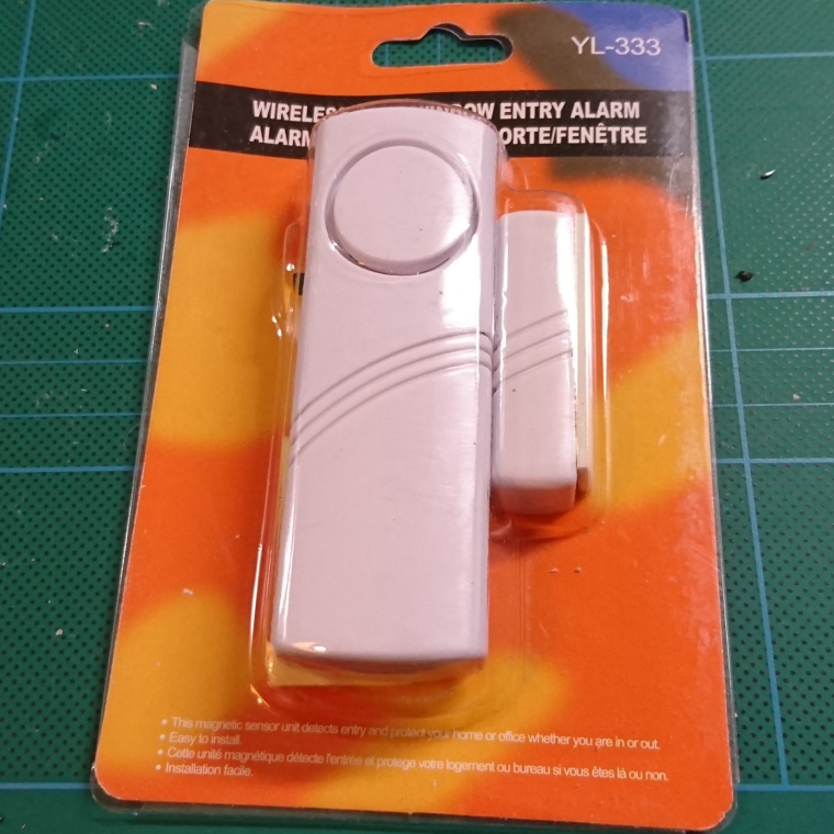
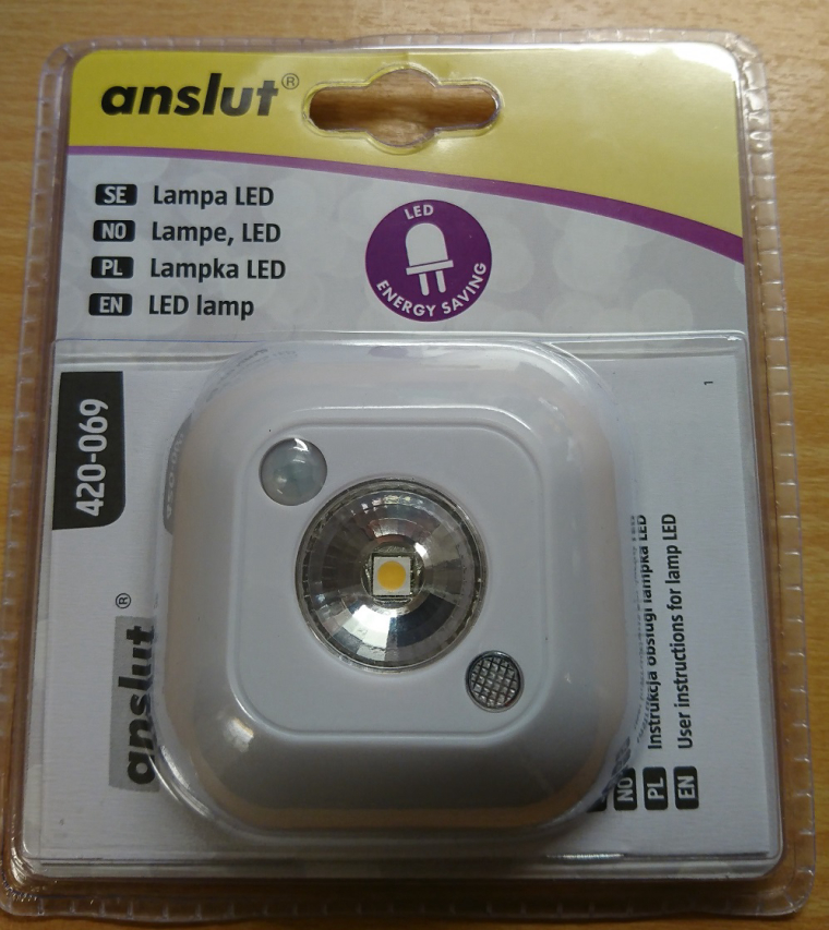
    I found a cheap (€5) battery powered motion sensor LED at jula.se that I couldn't resist to pry open.
    0_1485886713650_anslut.jpg

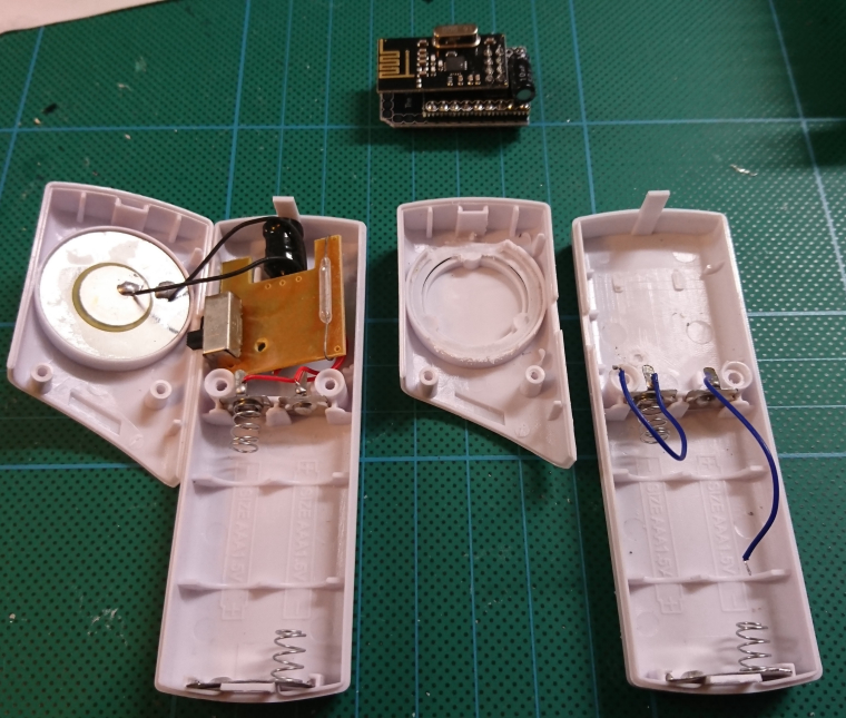
    Looking at the PCB I found the standard BISS0001 used in most PIR motion sensors.
    0_1485888098919_anslut.pcb.jpg
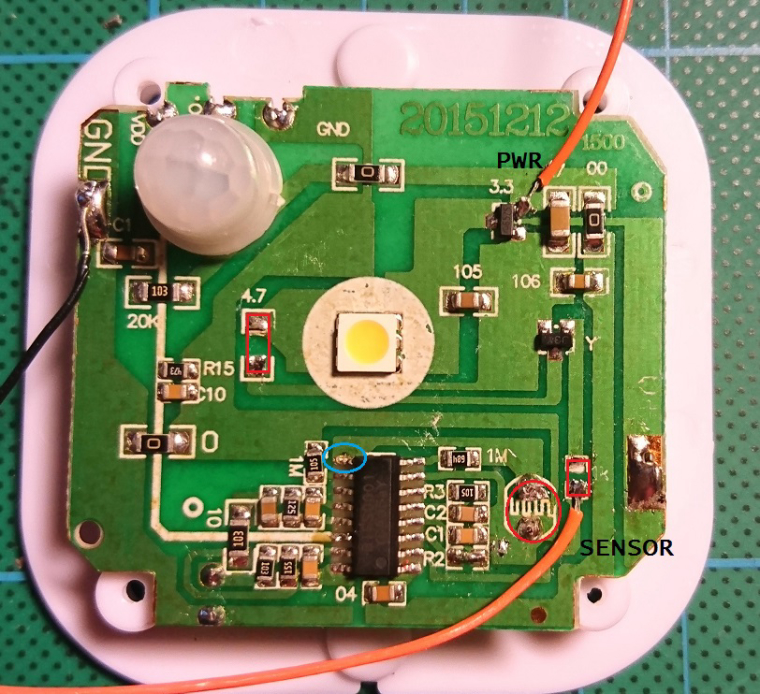
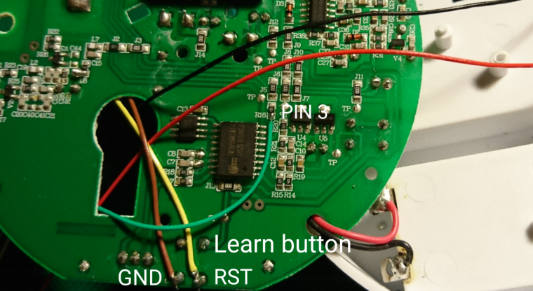
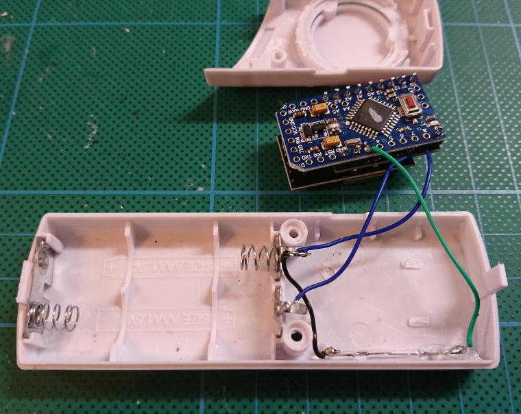
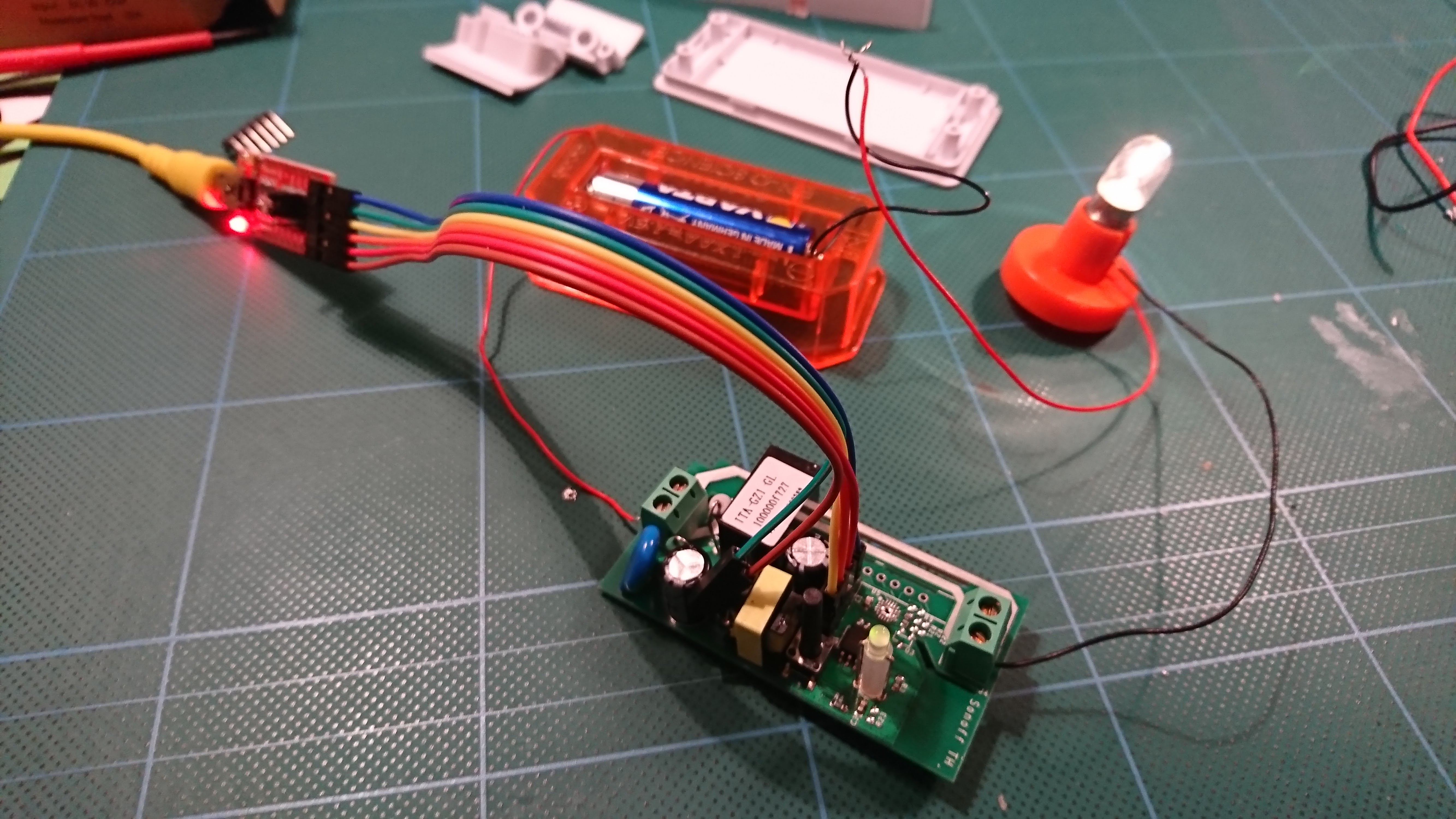
    I de-soldered LED resistor and the resistor connecting the IC with the transistor causing the LED to shine. The bottom orange cable is the sensor output going HIGH when motion is detected. In this sensor trigger time was set to 25s by a 10K resistor at R2, I have replaced it with a short=0 to only have part of a second output (look at the datasheet for more details). The photo resistor is also removed unless you only want night triggering. Pin 9 on the IC, blue circle, is used to enable/disable the sensor. I have left it untouched, for now.

    Since it's powered by 3xAAA=4,5V I take 3V from the top right VDC regulator (?).

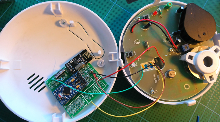
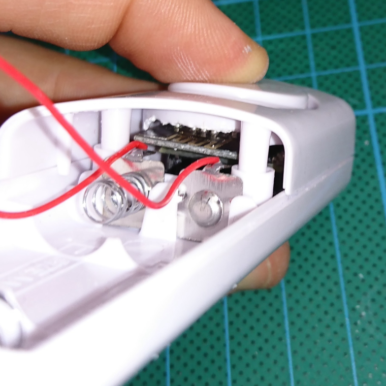
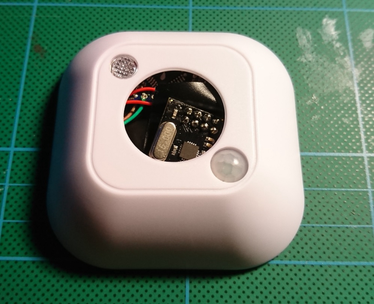
    It all fits just fine in the box..ehh
    0_1485905158978_anslut.done.jpg

    The example motion sketch have been used as base for my code. I have made some small changes. I disable motion detection for 30min after first trigger. I sleep for 6hours before reporting battery level. Interrupt is triggered by RISING.

    /**
     * The MySensors Arduino library handles the wireless radio link and protocol
     * between your home built sensors/actuators and HA controller of choice.
     * The sensors forms a self healing radio network with optional repeaters. Each
     * repeater and gateway builds a routing tables in EEPROM which keeps track of the
     * network topology allowing messages to be routed to nodes.
     *
     * Created by Henrik Ekblad <henrik.ekblad@mysensors.org>
     * Copyright (C) 2013-2015 Sensnology AB
     * Full contributor list: https://github.com/mysensors/Arduino/graphs/contributors
     *
     * Documentation: http://www.mysensors.org
     * Support Forum: http://forum.mysensors.org
     *
     * This program is free software; you can redistribute it and/or
     * modify it under the terms of the GNU General Public License
     * version 2 as published by the Free Software Foundation.
     *
     *******************************
     *
     * REVISION HISTORY
     * Version 1.0 - Henrik Ekblad
     *
     * DESCRIPTION
     * Motion Sensor example using HC-SR501
     * http://www.mysensors.org/build/motion
     *
     */
    
    // Enable debug prints
    #define MY_DEBUG
    
    // Enable and select radio type attached
    #define MY_RADIO_NRF24
    //#define MY_RADIO_RFM69
    
    #include <MySensors.h>
    #include <Vcc.h>
    
    const float VccMin        = 2.0*0.6;  // Minimum expected Vcc level, in Volts. Example for 2xAA Alkaline.
    const float VccMax        = 2.0*1.5;  // Maximum expected Vcc level, in Volts. Example for 2xAA Alkaline.
    const float VccCorrection = 1.0/1.0;  // Measured Vcc by multimeter divided by reported Vcc
    
    Vcc vcc(VccCorrection);
                            //  h      m      s       ms
    unsigned long SLEEP_TIME =  6UL * 60UL * 60UL * 1000UL; // Sleep time between reports (in milliseconds)
    unsigned long DISABLE_TIME =      30UL * 60UL * 1000UL; // Time until sensor is re-enabled after triggering (in milliseconds)
    #define MOTION_SENSOR_PIN 2   // The digital input you attached your motion sensor.  (Only 2 and 3 generates interrupt!)
    #define CHILD_ID 0   // Id of the sensor child
    
    // Initialize motion message
    MyMessage msg(CHILD_ID, V_TRIPPED);
    int wakeup = 0;
    
    void setup()
    {
      pinMode(MOTION_SENSOR_PIN, INPUT);      // sets the motion sensor digital pin as input
    }
    
    void presentation()
    {
      // Send the sketch version information to the gateway and Controller
      sendSketchInfo("Motion Sensor", "1.0");
    
      // Register all sensors to gw (they will be created as child devices)
      present(CHILD_ID, S_MOTION, "Motion tripped", true);
    }
    
    void loop()
    {
      // Read digital motion value
      bool tripped = digitalRead(MOTION_SENSOR_PIN) == HIGH;
    
      if (tripped) 
      {
        send(msg.set(1));  // Send tripped value to gw
        send(msg.set(0));  // Send tripped value to gw 
        // Ignore any motion for a set time
        sleep(DISABLE_TIME);
      }
    
      // Send battery level when waking up from long sleep
      if (wakeup == -1)
      {
        uint8_t batteryPcnt = static_cast<uint8_t>(0.5 + vcc.Read_Perc(VccMin, VccMax));
        // Send battery level, used as heartbeat of the sensor
        sendBatteryLevel(batteryPcnt);
      }
      
      // Sleep until interrupt comes in on motion sensor. Send update every two minute.
      wakeup = sleep(digitalPinToInterrupt(MOTION_SENSOR_PIN), RISING, SLEEP_TIME);
    }
    
    My Project

  • Nexa smoke alarm hack
    EfflonE Efflon

    Note, I take no responsibilities for modifications you do to your smoke alarm. Use a back up for safety.

    I have a few Nexa KD-101Lx smoke detektors with a built in 433MHz radio that just eats batteries so I had the idea to modify them to talk with a simple MySensors node.
    The construction is actually a alarm and a radio on the same PCB. Looking at the PCB and a bit of testing I found the connection between the smoke alarm and the radio part.
    0_1485604533822_nexa-pcb-label.png
    When the alarm triggers the pin is pulled high and since there already is a 10k pull-up resistor in place all that is needed is to add a cable to my sensor. The "learn" button is re-used for triggering reset and providing ground.
    The original radio is powered by 3xAA so I just cut the cable and re-soldered the cables to use only 2xAA's.
    I will use the newbiePCB for hooking things up and everything's seems to fit inside the case just fine.
    0_1485604635767_nexa-ready.jpg

    Here is the code that will run for the next couple of days.

    /**
     * The MySensors Arduino library handles the wireless radio link and protocol
     * between your home built sensors/actuators and HA controller of choice.
     * The sensors forms a self healing radio network with optional repeaters. Each
     * repeater and gateway builds a routing tables in EEPROM which keeps track of the
     * network topology allowing messages to be routed to nodes.
     *
     * Created by Henrik Ekblad <henrik.ekblad@mysensors.org>
     * Copyright (C) 2013-2015 Sensnology AB
     * Full contributor list: https://github.com/mysensors/Arduino/graphs/contributors
     *
     * Documentation: http://www.mysensors.org
     * Support Forum: http://forum.mysensors.org
     *
     * This program is free software; you can redistribute it and/or
     * modify it under the terms of the GNU General Public License
     * version 2 as published by the Free Software Foundation.
     *
     *******************************
     *
     * DESCRIPTION
     *
     * Simple fire alarm example modifying a Nexa KD-101L fire alarm
     * Connect digitial I/O pin 3 (FIRE_PIN below) with a 10K resistor to GND.
     * Also connect the FIRE_PIN between the IC and R16 (SMD103=10K).
     */
    
    
    // Enable debug prints to serial monitor
    #define MY_DEBUG 
    
    // Enable and select radio type attached
    #define MY_RADIO_NRF24
    
    #include <MySensors.h>
    #include <Vcc.h>
    
    const float VccMin        = 2.0*0.6;  // Minimum expected Vcc level, in Volts. Example for 2xAA Alkaline.
    const float VccMax        = 2.0*1.5;  // Maximum expected Vcc level, in Volts. Example for 2xAA Alkaline.
    const float VccCorrection = 1.0/1.0;  // Measured Vcc by multimeter divided by reported Vcc
    
    Vcc vcc(VccCorrection);
    
    // Pin connected to the alarm
    #define FIRE_PIN 3
    
    // Id of the sensor child
    #define CHILD_ID 0
    
    // Sleep time in ms        min     s      ms
    unsigned long SLEEP_TIME = 120UL * 60UL * 1000UL;
    
    MyMessage msg(CHILD_ID, V_TRIPPED);
    
    void setup()  
    {  
      // Setup the alarm
      pinMode(FIRE_PIN, INPUT);  
    }
    
    void presentation()  {
      // Send the sketch version information
      sendSketchInfo("Fire Alarm", "1.0");
      // Register sensor
      present(CHILD_ID, S_SMOKE, "Alarm tripped", true);
      // Send the current state
      //send(msg.set("0"));
    }
    
    
    void loop()
    {
      bool tripped = digitalRead(FIRE_PIN) == HIGH;
      
      if(tripped) {
        Serial.println("Fire!");
        send(msg.set(1), true);
        wait(1000);
      } else {
        Serial.println("All ok");
        send(msg.set(0), true);
        // Measure battery level
        uint8_t batteryPcnt = static_cast<uint8_t>(0.5 + vcc.Read_Perc(VccMin, VccMax));
        // Send battery level, used as heartbeat of the sensor
        sendBatteryLevel(batteryPcnt);
      }
      // Sleep until fire
      sleep(digitalPinToInterrupt(FIRE_PIN), HIGH, SLEEP_TIME);
    }
    
    My Project

  • Door sensor, remix of some MYS community efforts
    EfflonE Efflon

    This project is a remix of a few other MYS project. The base is the excellent Window Sensor with Sensebender (high WAF) where I thought I could get some use of the tiny jModule instead. I ended up ordering from a link to dirtyPCBs in the comments.
    This is the start, dirt cheap but still looks ok.
    0_1491512542575_mys-door-start.JPG
    Rip it open, de-solder the glass reed switch and don't bend the pins since that will most likely kill it. Use a dremmel and remove some excess plastic in the top part of the speaker fitting.
    0_1491512749706_mys-door.JPG
    Assemble your jModule. I didn't use any bent pins since the space is extremely limited.
    0_1491513025490_mys-door-pcb.JPG
    As you see, the wiring is just the reed switch to GND and 3. Power and GND to the edge of the jModule (on to VCC of pro mini). Since it's battery powered the pro mini LED is removed (destroyed :grin: ) and traces cut. Cut the corners of the pro mini (!) to make it fit.
    0_1491513534209_mys-door-end.JPG

    Last but not least, some code. I gave NodeManager by @user2684 a try and it makes things almost to easy :smile:

      /*
       * For v1.3
       * Register below your sensors
      */
      nodeManager.setBatteryMin(1.8);
      nodeManager.setBatteryMax(3.2);
      nodeManager.setBatteryReportCycles(2);
      nodeManager.registerSensor(SENSOR_DOOR,3);
      nodeManager.setSleep(SLEEP,3,HOURS);
      /*
       * Register above your sensors
      */
    

    Every 6 hous the sensor will report battery status. On open or close it will report state then go back to sleep.

    The second sensor took 15 minutes to assemble, quite ok imho...

    My Project

  • Housing/Box for ESP8266Wlan Gateway
    EfflonE Efflon

    I have a just tested a few wemos D1 mini pro from the Aliexpress/wemos store. They are top notch imho, you cannot find anything better for 5$ (of ESP8266 based boards). They are very small and come ready for stacking with extra boards. Fast shipping to...

    Enclosures / 3D Printing

  • Sonoff + MySensors mqtt gateway + Home-Assistant
    EfflonE Efflon

    Edit: This information is now maintained here and now includes both ethernet and mqtt gateway examples.

    I just got my hands on a Sonoff wifi switch and have adapted the MySensors mqtt gateway example to work work with the Sonoff relay and Home Assistant

    I have not used it with 220V yet but its tested as you can see.
    0_1484862399740_sonoff.jpg

    At start up the LED will blink twice once the presentation is done and then start in the off state.
    The button will toggle on off and send the state back to the gateway.
    The gateway can also send state to the Sonoff.
    If you have multiple Sonoff's they can all use the same mqtt topic as long as they don't have the same child id.

    /**
     * The MySensors Arduino library handles the wireless radio link and protocol
     * between your home built sensors/actuators and HA controller of choice.
     * The sensors forms a self healing radio network with optional repeaters. Each
     * repeater and gateway builds a routing tables in EEPROM which keeps track of the
     * network topology allowing messages to be routed to nodes.
     *
     * Created by Henrik Ekblad <henrik.ekblad@mysensors.org>
     * Copyright (C) 2013-2015 Sensnology AB
     * Full contributor list: https://github.com/mysensors/Arduino/graphs/contributors
     *
     * Documentation: http://www.mysensors.org
     * Support Forum: http://forum.mysensors.org
     *
     * This program is free software; you can redistribute it and/or
     * modify it under the terms of the GNU General Public License
     * version 2 as published by the Free Software Foundation.
     *
     *******************************
     *
     * REVISION HISTORY
     * Version 1.0 - Henrik Ekblad
     *
     * DESCRIPTION
     * The ESP8266 MQTT gateway sends radio network (or locally attached sensors) data to your MQTT broker.
     * The node also listens to MY_MQTT_TOPIC_PREFIX and sends out those messages to the radio network
     *
     * LED purposes:
     * - To use the feature, uncomment any of the MY_DEFAULT_xx_LED_PINs in your sketch
     * - RX (green) - blink fast on radio message recieved. In inclusion mode will blink fast only on presentation recieved
     * - TX (yellow) - blink fast on radio message transmitted. In inclusion mode will blink slowly
     * - ERR (red) - fast blink on error during transmission error or recieve crc error
     *
     * See http://www.mysensors.org/build/esp8266_gateway for wiring instructions.
     * nRF24L01+  ESP8266
     * VCC        VCC
     * CE         GPIO4
     * CSN/CS     GPIO15
     * SCK        GPIO14
     * MISO       GPIO12
     * MOSI       GPIO13
     *
     * Not all ESP8266 modules have all pins available on their external interface.
     * This code has been tested on an ESP-12 module.
     * The ESP8266 requires a certain pin configuration to download code, and another one to run code:
     * - Connect REST (reset) via 10K pullup resistor to VCC, and via switch to GND ('reset switch')
     * - Connect GPIO15 via 10K pulldown resistor to GND
     * - Connect CH_PD via 10K resistor to VCC
     * - Connect GPIO2 via 10K resistor to VCC
     * - Connect GPIO0 via 10K resistor to VCC, and via switch to GND ('bootload switch')
     *
      * Inclusion mode button:
     * - Connect GPIO5 via switch to GND ('inclusion switch')
     *
     * Hardware SHA204 signing is currently not supported!
     *
     * Make sure to fill in your ssid and WiFi password below for ssid & pass.
     */
     
    /**
     * Sonoff specific details (IM15116002)
     * 
     * The sonoff header left to right, relay above, LED below.
     *  [1]  vcc 3v3
     *   2   rx
     *   3   tx
     *   4   gnd
     *   5   
     *   
     * In arduinoIDE 1.6.* choose Generic ESP8226 module.
     * Hold Sonoff button when attaching FTDI to flash.
     */
    
    
    // Enable debug prints to serial monitor
    #define MY_DEBUG
    
    // Use a bit lower baudrate for serial prints on ESP8266 than default in MyConfig.h
    #define MY_BAUD_RATE 9600
    
    // No radio in Sonoff
    // Enables and select radio type (if attached)
    //#define MY_RADIO_NRF24
    //#define MY_RADIO_RFM69
    
    #define MY_GATEWAY_MQTT_CLIENT
    #define MY_GATEWAY_ESP8266
    
    // Set this node's subscribe and publish topic prefix
    #define MY_MQTT_PUBLISH_TOPIC_PREFIX "sonoff-out"
    #define MY_MQTT_SUBSCRIBE_TOPIC_PREFIX "sonoff-in"
    
    // Set MQTT client id
    #define MY_MQTT_CLIENT_ID "mysensors-sonoff-1"
    
    // Enable these if your MQTT broker requires usenrame/password
    //#define MY_MQTT_USER "username"
    //#define MY_MQTT_PASSWORD "password"
    
    // Set WIFI SSID and password
    #define MY_ESP8266_SSID "SSiD"
    #define MY_ESP8266_PASSWORD "password"
    
    // Set the hostname for the WiFi Client. This is the hostname
    // it will pass to the DHCP server if not static.
    #define MY_ESP8266_HOSTNAME "mqtt-sensor-gateway-sonoff-1"
    
    // Enable MY_IP_ADDRESS here if you want a static ip address (no DHCP)
    //#define MY_IP_ADDRESS 192,168,178,87
    
    // If using static ip you need to define Gateway and Subnet address as well
    #define MY_IP_GATEWAY_ADDRESS 192,168,0,1
    #define MY_IP_SUBNET_ADDRESS 255,255,255,0
    
    
    // MQTT broker ip address.
    #define MY_CONTROLLER_IP_ADDRESS 192, 168, 0, 100
    
    // The MQTT broker port to to open
    #define MY_PORT 1883
    
    // Not tested for Sonoff
    /*
    // Enable inclusion mode
    #define MY_INCLUSION_MODE_FEATURE
    // Enable Inclusion mode button on gateway
    #define MY_INCLUSION_BUTTON_FEATURE
    // Set inclusion mode duration (in seconds)
    #define MY_INCLUSION_MODE_DURATION 60
    // Digital pin used for inclusion mode button
    #define MY_INCLUSION_MODE_BUTTON_PIN  3
    
    // Set blinking period
    #define MY_DEFAULT_LED_BLINK_PERIOD 300
    
    // Flash leds on rx/tx/err
    #define MY_DEFAULT_ERR_LED_PIN 16  // Error led pin
    #define MY_DEFAULT_RX_LED_PIN  16  // Receive led pin
    #define MY_DEFAULT_TX_LED_PIN  16  // the PCB, on board LED
    */
    
    #include <ESP8266WiFi.h>
    #include <MySensors.h>
    #include <Bounce2.h>
    
    #define BUTTON_PIN 0  // Sonoff pin number for button
    #define RELAY_PIN 12  // Sonoff pin number for relay 
    #define LED_PIN 13    // Sonoff pin number for LED
    #define RELAY_ON 1
    #define RELAY_OFF 0
    #define LED_ON 0
    #define LED_OFF 1
    
    // Id of the sensor child
    // Set unique id for each sonoff if sub/pub on same mqtt topic
    #define CHILD_ID 0
    
    Bounce debouncer = Bounce(); 
    int oldValue = 0;
    bool state = false;
    
    MyMessage msg(CHILD_ID,V_STATUS);
    
    void setup()  
    {  
      // Setup the button
      pinMode(BUTTON_PIN, INPUT_PULLUP);
    
      // After setting up the button, setup debouncer
      debouncer.attach(BUTTON_PIN);
      debouncer.interval(5);
    
      // Make sure relays and LED are off when starting up
      digitalWrite(RELAY_PIN, RELAY_OFF);
      digitalWrite(LED_PIN, LED_OFF);
    
      // Then set relay pins in output mode
      pinMode(RELAY_PIN, OUTPUT);
      pinMode(LED_PIN, OUTPUT);   
    }
    
    void presentation()  {
      // Send the sketch version information
      sendSketchInfo("Sonoff", "1.0");
      // Register sensor
      present(CHILD_ID, S_BINARY);
      // Send the current state
      send(msg.set(state?true:false));
      // Blink when ready
      blink();
    }
    
    
    void loop()
    {
      debouncer.update();
      // Get the update value
      int value = debouncer.read();
      if (value != oldValue && value==0) {
        // Toggle the state
        state = state?false:true;
        // Change relay state
        digitalWrite(RELAY_PIN, state?RELAY_ON:RELAY_OFF);
        // Change LED state
        digitalWrite(LED_PIN, state?LED_ON:LED_OFF);
        // Send new state
        send(msg.set(state)); 
      }
      oldValue = value;
    }
    
    void receive(const MyMessage &message)
    {
      // We only react on status messages from the controller
      // to this CHILD_ID.
      if (message.type==V_STATUS  && message.sensor==CHILD_ID) {
        // Change relay state
        // Only switch if the state is new
        if (message.getBool() != state) {
          state = message.getBool();
          // Change relay state
          digitalWrite(RELAY_PIN, state?RELAY_ON:RELAY_OFF);
          // Change LED state
          digitalWrite(LED_PIN, state?LED_ON:LED_OFF);
           // Send the current state
          send(msg.set(state));  
        }
      }
    }
    
    void blink()
    {
      digitalWrite(LED_PIN, digitalRead(LED_PIN)?LED_ON:LED_OFF);
      wait(200);
      digitalWrite(LED_PIN, digitalRead(LED_PIN)?LED_ON:LED_OFF);
      wait(200);
      digitalWrite(LED_PIN, digitalRead(LED_PIN)?LED_ON:LED_OFF);
      wait(200);
      digitalWrite(LED_PIN, digitalRead(LED_PIN)?LED_ON:LED_OFF);
    }


    The HASS config is not much. Using the persistence file will make HASS restore the desired state if the Sonoff loses power etc.

    mysensors:
      gateways:
        - device: mqtt
          persistence_file: '/home/homeassistant/.homeassistant/sonoff.json'
          topic_in_prefix: 'sonoff-out'
          topic_out_prefix: 'sonoff-in'
      debug: false
      optimistic: false
      persistence: true
      retain: true
      version: 2.0
    
    My Project mqtt sonoff home assistant

  • Wemos XI
    EfflonE Efflon

    @korttoma Why use ESP8266? isnt it 328 clone so you could use Mini pro in arduino ?

    Hardware

  • 💬 Easy/Newbie PCB for MySensors
    EfflonE Efflon

    @mfalkvidd I ordered January 2 and can't remember what version was stated. I'm quite sure I picked Itead because it had a higher version numer (and a slightly higher price), honestly don't remember. All I know is that I didn't read this thread but rather just browsed through the page and clicked order. Afterwards I realized it wasn't clear if it was the 5V or 3.3V version but the order said 5x5cm. I also missed to choose color but "grönt är skönt".
    Guess what confused me most was the statement "It may say another rev. at the orderpage but this is not EasyPCB rev but the rev for manufacturer." causing me to be trigger happy :smile:

    OpenHardware.io mysensors battery easy newbie pcb mysx

  • 💬 Battery Powered Sensors
    EfflonE Efflon

    @GertSanders Thanks for you explanation. I thought vvc on the short end next to rx was going through the voltage regulator just as RAW. Anyhow I have already de-soldered the LED's and are powering through vcc next to A3. Apparently my voltage regulators are bad so I'll cut the lines and give it a try and hope power consumption stays low.

    Announcements battery

  • JULA motion LED hack
    EfflonE Efflon

    Ehh, detect motion :smiley:

    My Project

  • 💬 Sonoff relay using MySensors ESP8266 wifi or mqtt gateway
    EfflonE Efflon

    This is not listed as a gateway but under sensors & actuators but maybe a "s/and/relay using" would be a fix of the headline. I selected the mqtt gateway example just because I have a few other NodeMCU's working as just MYS sensors with no radio but it's trivial to just re-use code for any of the other gateways, as you all know. I choose the mqtt addition just for fun and know there are other mqtt examples but nothing working out of the box with my HASS + MYS + mqtt setup. Regarding the gateway naming, at least I don't know any other way of using MYS and ESP8266 than using the gateway sketches with a disabled radio. What should they be called, just node? At the same time, adding a radio to the Sonoff and it's a gateway...

    OpenHardware.io mqtt sonoff home assistan esp8266

  • 💬 NodeManager
    EfflonE Efflon

    Wow! This seems to make things extremely simple. The documentation is really good but I wish you had a few example sketches to make things even more easy (and help us who can't bother to read all documentation ;D ).

    OpenHardware.io contest2017 arduino newbie mysensors battery sensor

  • 💬 Sonoff relay using MySensors ESP8266 wifi or mqtt gateway
    EfflonE Efflon

    @warmaniac the sonoff works just like any sensor except its configured as a gateway since that is what is needed for esp8266+mysensors . Mqtt or ethernet/wifi is just a matter of taste and your setup, skip mqtt if you don't have anything else using it.

    OpenHardware.io mqtt sonoff home assistan esp8266

  • 💬 Sonoff relay using MySensors ESP8266 wifi or mqtt gateway
    EfflonE Efflon

    @user2684 Thanks for reporting. I have updated the instructions with the Sonoff details.

    OpenHardware.io mqtt sonoff home assistan esp8266
  • Login

  • Don't have an account? Register

  • Login or register to search.
  • First post
    Last post
0
  • MySensors
  • OpenHardware.io
  • Categories
  • Recent
  • Tags
  • Popular