@bisschopsr yes, the battery inside the “16 LED Solar Power Motion Sensor Security Lamp Outdoor Waterproof Light” (http://www.ebay.com/itm/271693521438) is 3.7v 800mAh.
E
Elfnoir
@Elfnoir
Posts
-
Solar Powered Mini-Weather Station -
Solar Powered Mini-Weather Station@Renard c'est bien l'arduino qui gère la décharge et envoi l'info à Domoticz; c'est pour cela que tu dois étalonner le min/max avec le potentiomètre
it is the Arduino which manages the discharge and send the info to Domoticz ; that's why you have to calibrate the min / max with the potentiometer@bisschopsr If I well understand your question, the module which take the solar power to charge the battery with providing in the same time power to the arduino, and provide power of the battery to the arduino when there is no sun or at night: it's the Lipo Ride. There is no monitoring from the Arduino to the Lipo, but the Arduino read the level of voltage coming from the battery and send it to Domoticz.
Do I understand well your question please? -
Solar Powered Mini-Weather Station@Renard : Bonjour! Je fais le raccordement cette semaine j'espère, je galère sur la déclaration dans Domoticz et l'étalonnage pour controler la charge de la batterie, mais je dirais:
- OUT+ et - sur RAW et GND de l'Arduino
- B+ B- à la batterie
- "+ et -" au panneau solaire, c'est ce qu'il me semble sur les photos.
@bisschopsr : Hi, There is no charge controler 5 or 12 volts. On my Fritzing to understand better the scheme (Post #70), I draw batteries and solar panel, but Fritzings following are with 12volts charger, I don't know why. If you purchased a solar lamp, it's to avoid 5 or 12volts charger and use the sun ;-)
-
Solar Powered Mini-Weather StationHi,
It means that there is no possibility to implement wind speed on this weather station... ok.
I've just received the good Li-Ion charging component, I can continue with the construction!I'll post if I will be facing for some trouble, or when it will be finished.
-
Mysensors on ESP8266- ESP01?@Dwalt Thanks for your feedback! Do you have any URL / tutorial to explain how to flash an ESP8266 with MySensors sketches please?
Also what kind of ESP8266 do you use? Is it ESP8266-012 please? -
Air Quality SensorHi,
Can you check the reception level?
I had same behaviour with an old temperature/humidity module; need to move it to another place in the room, and works perfectly now :-) -
Mysensors on ESP8266- ESP01?Hi,
I have few ESP8266-ESP01 from a previous project.
Do you know if it's possible to use it in place of NRF24L01?
I know that we can configure it in LUA or Arduino language directly; Do you know if we can upload MySensors sketch Child on it, for example the Relay sketch? Ok, there are only 2 GPIO, but for many use it's enough; Also, you can avoid to have Atmega+NRF for each Child, reducing the volume of a Child.
Thanks for your feedback, and sorry if it's a silly question!
-
Solar Powered Mini-Weather Station@peerkersezuuker 0_1459719366114_Weather Station.fzz
And thanks for your feedback and support!
-
Solar Powered Mini-Weather StationHi,
Thanks for your help! I'm waiting for the LiPo charger, because I purchased a wrong one to pursue my implementation...- Could you tell me how I can comment our line 51 please? Just like this?
'dht.setup(HUMIDITY_SENSOR_DIGITAL_PIN); - Also, do you have already implement the Wind Speed Module, or it's under shipment? Do you use Domoticz as domotic software? It's to know how to implement this kind of child on it?
- Is the solar panel providing enough power to have the weather station always working? (I'm living in France on Paris latitude, and I would like to know if the quantity of sun is enough, or I need a second solar panel)
- And it appears my Barometric Pressure sensor gave me also the humidity and temperature; Why do we have 1DHT22 and 1BMP180 ?
- And finally, how do you deal with the battery level, as I didn't see at the beginning of this post how it is implemented inside Vera? Because I would like to implement it in Domoticz
Many thanks for your feedback!
- Could you tell me how I can comment our line 51 please? Just like this?
-
Solar Powered Mini-Weather StationHi,
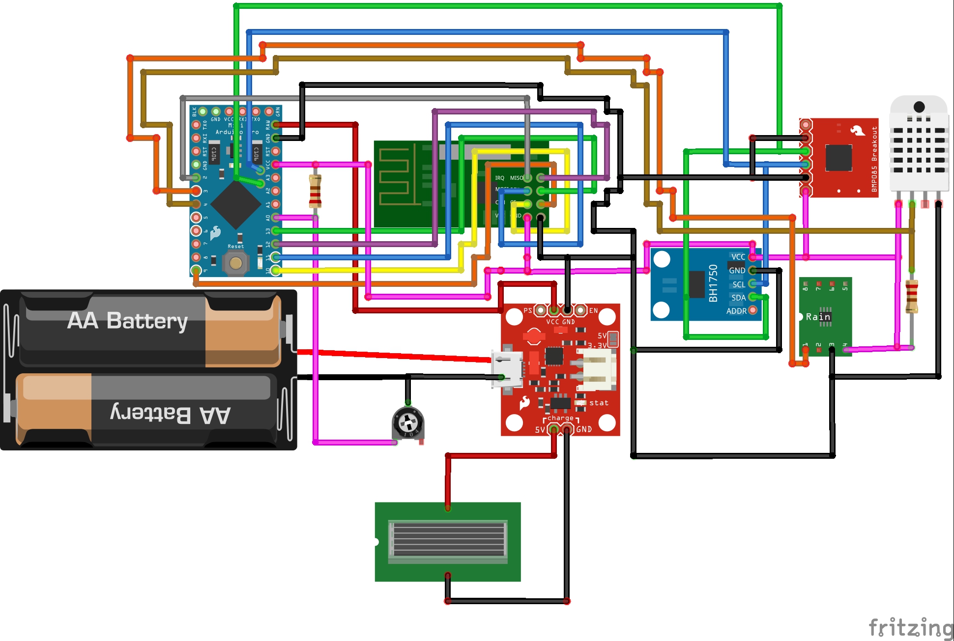
The left resistor is a 1Mohm 2W(I'll confirm the power value once I'll received it), the right one is 4,7kohm, 1/4W.
For the Hardware, I read the beginning of the post, but unfortunately I'm also a newby, and need to have a validation of this diagram, because I'm not sure if it is correct, and I don't want to burn my house if I'll do cabling mistakes ;-)
I am not able to put the file created under fritzing, but if someone wants it, tell me how to do it please.Thanks for your feedback!
Regards. -
Solar Powered Mini-Weather StationHi,
Here is the fritzing shema ; could you please tell me if it is correct before I begin the building of the weather station ?
Thanks for your support !
-
[contest] My 4-in1 LED-dimmer/motion/temp-hum sensorHi!
Nice project, and I'm really interested on it!!
Unfortunately, when I copy/paste your script, I've an error on line 44 during the check in Arduino 1.6.7 for "MySensor gw(9,10);", the message is:error: no matching function for call to 'MySensor::MySensor(int, int)'
Could you please tell me what could I do to make this script working?
Thanks for your answer! -
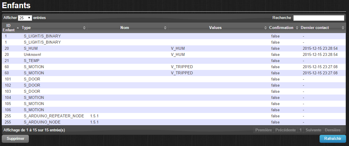
3 BinarySwitch + 3 motionsHi,
I tried to integrate 3 BinarySwitch and 3 motions around the same Arduino Pro.
The 3 Binary are working perfectly, but on the 3 motions, they are always at '1' value, despite I move them.
Do you know if there is a limit of the number of sensors per Ardino Pro?
Or simply I did mistakes on the script:/** * The MySensors Arduino library handles the wireless radio link and protocol * between your home built sensors/actuators and HA controller of choice. * The sensors forms a self healing radio network with optional repeaters. Each * repeater and gateway builds a routing tables in EEPROM which keeps track of the * network topology allowing messages to be routed to nodes. * * Created by Henrik Ekblad <henrik.ekblad@mysensors.org> * Copyright (C) 2013-2015 Sensnology AB * Full contributor list: https://github.com/mysensors/Arduino/graphs/contributors * * Documentation: http://www.mysensors.org * Support Forum: http://forum.mysensors.org * * This program is free software; you can redistribute it and/or * modify it under the terms of the GNU General Public License * version 2 as published by the Free Software Foundation. * ******************************* * * DESCRIPTION * * Simple binary switch example * Connect button or door/window reed switch between * digitial I/O pin 3 (BUTTON_PIN below) and GND. * http://www.mysensors.org/build/binary */ #include <MySensor.h> #include <SPI.h> #include <Bounce2.h> #define CHILD_ID_1 101 // ID 1 #define CHILD_ID_2 102 // ID 2 #define CHILD_ID_3 103 // ID 3 #define CHILD_ID_4 104 // ID 4 #define CHILD_ID_5 105 // ID 5 #define CHILD_ID_6 106 // ID 6 #define BUTTON_PIN_1 3 // Arduino Digital I/O pin for button/reed switch #define BUTTON_PIN_2 4 // Arduino Digital I/O pin for button/reed switch #define BUTTON_PIN_3 5 // Arduino Digital I/O pin for button/reed switch #define BUTTON_PIN_4 6 // Arduino Digital I/O pin for button/reed switch #define BUTTON_PIN_5 7 // Arduino Digital I/O pin for button/reed switch #define BUTTON_PIN_6 8 // Arduino Digital I/O pin for button/reed switch MySensor gw; Bounce debouncer1 = Bounce(); Bounce debouncer2 = Bounce(); Bounce debouncer3 = Bounce(); Bounce debouncer4 = Bounce(); Bounce debouncer5 = Bounce(); Bounce debouncer6 = Bounce(); int oldValue1=-1; int oldValue2=-1; int oldValue3=-1; int oldValue4=-1; int oldValue5=-1; int oldValue6=-1; // Change to V_LIGHT if you use S_LIGHT in presentation below MyMessage msg1(CHILD_ID_1,V_TRIPPED); MyMessage msg2(CHILD_ID_2,V_TRIPPED); MyMessage msg3(CHILD_ID_3,V_TRIPPED); MyMessage msg4(CHILD_ID_4,V_TRIPPED); MyMessage msg5(CHILD_ID_5,V_TRIPPED); MyMessage msg6(CHILD_ID_6,V_TRIPPED); void setup() { gw.begin(); // Setup the button pinMode(BUTTON_PIN_1,INPUT); pinMode(BUTTON_PIN_2,INPUT); pinMode(BUTTON_PIN_3,INPUT); pinMode(BUTTON_PIN_4,INPUT); pinMode(BUTTON_PIN_5,INPUT); pinMode(BUTTON_PIN_6,INPUT); // Activate internal pull-up digitalWrite(BUTTON_PIN_1,HIGH); digitalWrite(BUTTON_PIN_2,HIGH); digitalWrite(BUTTON_PIN_3,HIGH); digitalWrite(BUTTON_PIN_4,LOW); digitalWrite(BUTTON_PIN_5,LOW); digitalWrite(BUTTON_PIN_6,LOW); // After setting up the button, setup debouncer debouncer1.attach(BUTTON_PIN_1); debouncer1.interval(5); debouncer2.attach(BUTTON_PIN_2); debouncer2.interval(5); debouncer3.attach(BUTTON_PIN_3); debouncer3.interval(5); debouncer4.attach(BUTTON_PIN_4); debouncer4.interval(5); debouncer5.attach(BUTTON_PIN_5); debouncer5.interval(5); debouncer6.attach(BUTTON_PIN_6); debouncer6.interval(5); // Register binary input sensor to gw (they will be created as child devices) // You can use S_DOOR, S_MOTION or S_LIGHT here depending on your usage. // If S_LIGHT is used, remember to update variable type you send in. See "msg" above. gw.present(CHILD_ID_1, S_DOOR); gw.present(CHILD_ID_2, S_DOOR); gw.present(CHILD_ID_3, S_DOOR); gw.present(CHILD_ID_4, S_MOTION); gw.present(CHILD_ID_5, S_MOTION); gw.present(CHILD_ID_6, S_MOTION); } // Check if digital input has changed and send in new value void loop() { debouncer1.update(); // Get the update value int value1 = debouncer1.read(); if (value1 != oldValue1) { // Send in the new value gw.send(msg1.set(value1==HIGH ? 1 : 0)); oldValue1 = value1; } debouncer2.update(); // Get the update value int value2 = debouncer2.read(); if (value2 != oldValue2) { // Send in the new value gw.send(msg2.set(value2==HIGH ? 1 : 0)); oldValue2 = value2; } debouncer3.update(); // Get the update value int value3 = debouncer3.read(); if (value3 != oldValue3) { // Send in the new value gw.send(msg3.set(value3==HIGH ? 1 : 0)); oldValue3 = value3; } debouncer4.update(); // Get the update value int value4 = debouncer4.read(); if (value4 != oldValue4) { // Send in the new value gw.send(msg4.set(value4==HIGH ? 1 : 0)); oldValue4 = value4; } debouncer5.update(); // Get the update value int value5 = debouncer5.read(); if (value5 != oldValue5) { // Send in the new value gw.send(msg5.set(value5==HIGH ? 1 : 0)); oldValue5 = value5; } debouncer6.update(); // Get the update value int value6 = debouncer6.read(); if (value6 != oldValue6) { // Send in the new value gw.send(msg6.set(value6==HIGH ? 1 : 0)); oldValue6 = value6; } }Thanks for your support!
-
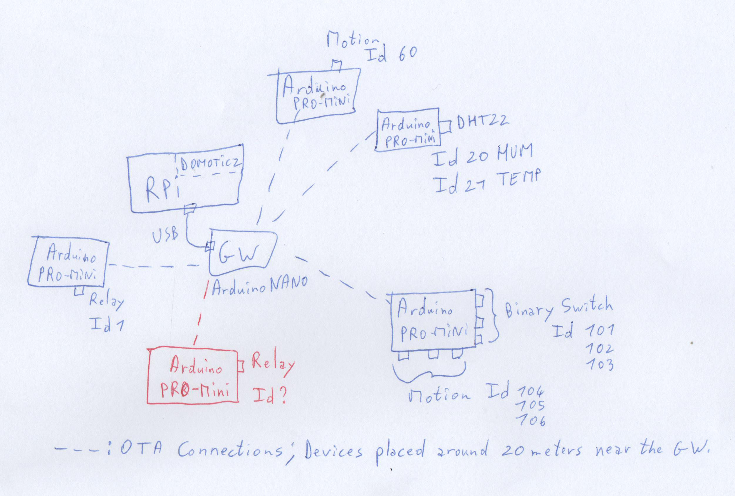
How to define Relay IdHi,
Thanks for these feedback!
I have some adding questions, or need of precision: You mean it doesn't matter to put the same script on another Arduino with Relay sensor, like my beautiful (...) design, but no conlift will result with this configuration?:
Because they are some conflict on my MySensors network under Domoticz:
Do you know this issue is coming from please?
Thanks for your support. -
How to define Relay IdHi,
I've just finished my first Relay with this script: http://www.mysensors.org/build/relay
And it's working :-) with child Id #1
I would like to add another Arduino with the same script for another room in my house, then I will have 2 Relays Sensors on the same network.
I'm on RPI with Domoticz, and understood the Id is not provided automatically, but you have to force it in the script; it's what I've done for a HUM/TEMP sensor (Id#20,21), and a motion sensor (Id#60).- If I create a new relay actuator, where in the script can I modify this Id # as there is no '#define CHILD_ID xx' in this script?
- What should I have to change if I want for example a Relay with Id 30, and another one 31?
- Do I understand well when I write that RPI+Domoticz+GW MySensors doesn't provide Auto Id, and you have to fill-in directly inside the script you upload into the sensors?
Many thanks for your help!
Regards. -
Error sending switch command, check device/hardware !When the GW booting in Domoticz, I add no information on the Release used.
In Domoticz, the Release was '?'
I received all information from my sensors, but not able to send status modifications (ON/OFF).The GW I used was an arduino pro mini plugged in RPI with a TTL adaptator.
Now I'm with an arduino UNO plugged directly to my RPI, and I purchased a NANO! -
Error sending switch command, check device/hardware !Hi,
I restart the sensor/actuator and the GW again without good results.
But it appears I had 2 GW broken!Now I build a new one, and all is running good. Thanks!
-
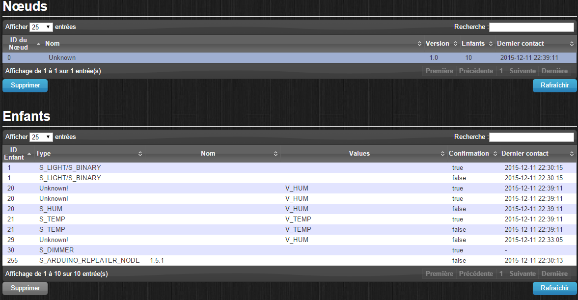
Error sending switch command, check device/hardware !Hi,
Despite I turn on and turn off the GW, turn on and turn off the RPI, and reinstall completely the GW, each time I reboot the RPI a new/same sensor appears:
If I click on Refresh, nothing happend. I try also to put the GW directly to the RPI, not through a USB port self powered for the same result. Last try is to reinstall Domoticz (already done a few days ago...but with not), or go to another interface on RPI for MySensors. -
Error sending switch command, check device/hardware !Hi!
I have the same behaviour on Domoticz running on a Raspberry PI type A Image v2.3530 or a Windows PC with Domoticz v2.3771.
I've created DIY Humidity Motion and Door Sensors working fine.
Unfortunately with Relay or Dimmer Sensors DIY, each time I try to turn ON or OFF, I have the same message: "Error sending switch command, check device/hardware !"
I try to changed GW, sensors, ... but there is the same situation, and nothing is indicated in the Domoticz log.
On the Sensor log, we can see only read and send from another sensor, but nothing from GW.
I didn't implemant an inclusion button as all my sensors are listed in Domoticz; do you know where I could try to troubleshootig now please?
Thanks for your help! -
Req IdHi,
I erase my arduino with EEPROM_clear script, and It works now.
Thanks.