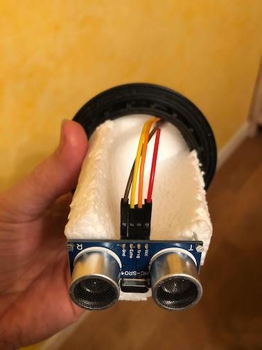
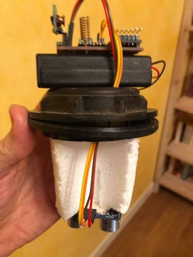
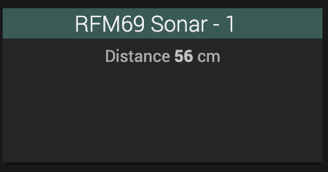
My first RFM69 Battery sensor: an ultrasonic sonar to measure the level of my fuel tank (don't laugh, winters can be cold in Burgundy :-) )
Many thanks to @sundberg84 and @mfalkvidd for advice to the Newbie i am and to @Gerator for the RFM69 gateway
My first RFM69 Battery sensor: an ultrasonic sonar to measure the level of my fuel tank (don't laugh, winters can be cold in Burgundy :-) )
Many thanks to @sundberg84 and @mfalkvidd for advice to the Newbie i am and to @Gerator for the RFM69 gateway
Hello here is an example i use at home: sending value 99 to node n°1
#define TARGET_NODE 1 // Id node Relay entree et couloir au tableau electrique

MyMessage MsgRelayGlobal(0,V_STATUS); // Message for the Relay actuator on node id 1, sensor 0

  // set the Destination of message to the node id of the relay actuator
  MsgRelayGlobal.setDestination(TARGET_NODE);

      MsgRelayGlobal.set( (const uint8_t ) 99 );
      Serial.println("Send Message to node 1");
      send(MsgRelayGlobal); // send message to node id 1
and here an example of how to deal with the message at target node:
void MyRelay::Receive(const MyMessage &message) {
  uint8_t payload= 0;

  payload= message.getByte();
  if  (message.type==V_STATUS) {
      if (payload==99) {
      // do something
I confirm care has to be taken: some brands want to lock you, the worst being Tuya, their devices are programmed in a way for them to work only with their gateway.
I’m very happy with the « silvercrest » gateway ; it works well and there is an « easy » hack to gain control of it there: https://paulbanks.org/projects/lidl-zigbee/#overview
(and here for french speaking people: https://faire-ca-soi-meme.fr/domotique/2021/03/22/hack-detournement-de-la-passerelle-lidl-silvercrest/)
@sundberg84 Thank you
My knowledge being very limited, i understand this might be difficult for my to go on the RFM69 version ?
Hopefully, my nrf24 network based on your designs works well :-)
Here is what i have tried:
I try using GPIO 2 and 15 to pilot the RFM69
here an extract of my GatewayESP8266.ino
// Enable debug prints to serial monitor
#define MY_DEBUG

// Use a bit lower baudrate for serial prints on ESP8266 than default in MyConfig.h
#define MY_BAUD_RATE 9600

// Enables and select radio type (if attached)
//#define MY_RADIO_RF24
#define MY_RADIO_RFM69

#define MY_IS_RFM69HW // Omit if your RFM is not "H"
#define MY_RFM69_IRQ_PIN 2
#define MY_RFM69_IRQ_NUM MY_RFM69_IRQ_PIN
#define MY_RFM69_CS_PIN 15 // NSS. Use MY_RFM69_SPI_CS for older versions (before 2.2.0)

../..

void setup()
{
   pinMode(MY_RFM69_IRQ_PIN, OUTPUT);
   pinMode(MY_RFM69_CS_PIN, OUTPUT);

	// Setup locally attached sensors
}

../..

void loop()
{
	// Send locally attached sensors data here
  digitalWrite(MY_RFM69_IRQ_PIN, HIGH);
delay(1000);
digitalWrite(MY_RFM69_IRQ_PIN, LOW);
delay(1000);
}
What's going wrong is i need to unplug the wire to GPIO2 at boot time unless it won't boot
then if i do that and replug the wire after boot, TFM is not initialized properly and
i get this log:
MCO:BGN:INIT GW,CP=RRNGE---,FQ=80,REL=255,VER=2.3.2
114 TSF:LRT:OK
130 TSM:INIT
143 TSF:WUR:MS=0
163 TSM:INIT:TSP OK
184 TSM:INIT:GW MODE
206 TSM:READY:ID=0,PAR=0,DIS=0
238 MCO:REG:NOT NEEDED
scandone
1311 GWT:TIN:CONNECTING...
2339 GWT:TIN:CONNECTING...
scandone
state: 0 -> 2 (b0)
state: 2 -> 3 (0)
state: 3 -> 5 (10)
add 0
aid 2

connected with TPLINK_BUREAU, channel 1
dhcp client start...
cnt
3168 GWT:TIN:CONNECTING...
ip:192.168.1.50,mask:255.255.255.0,gw:192.168.1.1
4329 GWT:TIN:CONNECTING...
4357 GWT:TIN:IP: 192.168.1.50
4389 MCO:BGN:STP
pm open,type:2 0
14407 MCO:BGN:INIT OK,TSP=1
14436 TSM:READY:NWD REQ
15462 ?TSF:MSG:SEND,0-0-255-255,s=255,c=3,t=20,pt=0,l=0,sg=0,ft=0,st=OK:
My knowlegde in electronics is level zero unfortunalty
The adafruit Huzzah documentation states that
GPIO #2, is also used to detect boot-mode. It also is connected to the blue LED that is near the WiFi antenna. It has a pullup resistor connected to it, and you can use it as any output (like #0) and blink the blue LED.
So i thought i could wire directly GPIO2 to DIO0 on the RFM69 like explained https://www.mysensors.org/build/connect_radio but obviously i do something wrong
Please Help :-)
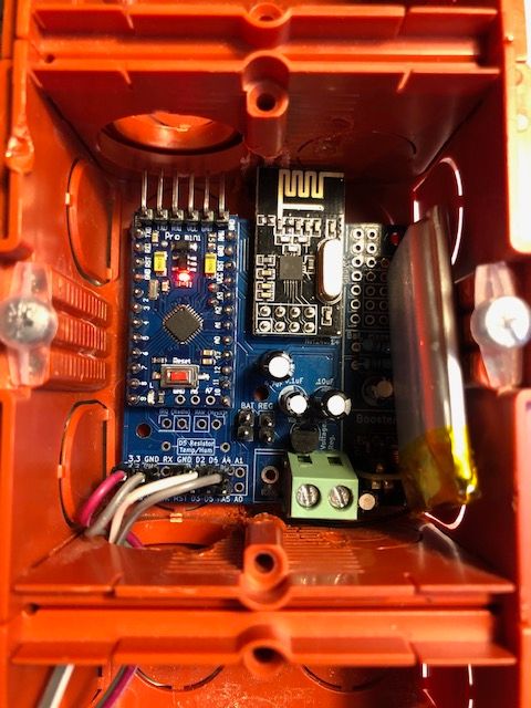
@mfalkvidd You're right: For production i'm going to build isolation for the sensor not to be in contact
Anyway: The flash point of domestic fuel oil is 55 ° C, which means that fuel oil cannot ignite below this temperature. In addition, in its liquid form, fuel oil is non-flammable at room temperature.
Thanks to @sundberg84
My Nrf24 gateaway is know quasi professionnal !
Can't wait to test the RFM69 version
I guess this means i finally managed to get it working:
4131 MCO:BGN:STP
4133 MCO:BGN:INIT OK,TSP=1
4135 TSM:READY:NWD REQ
4139 ?TSF:MSG:SEND,0-0-255-255,s=255,c=3,t=20,pt=0,l=0,sg=0,ft=0,st=OK:
pm open,type:2 0
30149 TSF:MSG:READ,5-5-255,s=255,c=3,t=7,pt=0,l=0,sg=0:
30155 TSF:MSG:BC
30157 TSF:MSG:FPAR REQ,ID=5
30159 TSF:PNG:SEND,TO=0
30161 TSF:CKU:OK
30163 TSF:MSG:GWL OK
30641 TSF:MSG:SEND,0-0-5-5,s=255,c=3,t=8,pt=1,l=1,sg=0,ft=0,st=OK:0
32650 TSF:MSG:READ,5-5-0,s=255,c=3,t=24,pt=1,l=1,sg=0:1
32655 TSF:MSG:PINGED,ID=5,HP=1
@NeverDie avoid tuya devices: they are intendly made to work only with the tuya app.
people try to work this around , for instance in ZHA quirks, but this is a nightmare of reverse engineering
Hello, certainly yes; anyhow, my setup is quite experimental yet:
I will post more details when my config is better.
excellent!
Thank you @CodeGarage , you really thrive !
As for the suggestions, i would say most important point would be to look at the project code base.
I guess the development branch has quiet evolved since the 2.3.2 release.
Next would be to sort the features and decide a roadmap for mysensors because the project can live only if it evolves
Long live MySensors!
@scalz @Sasquatch Thank you for suggestions, i will test next week-end
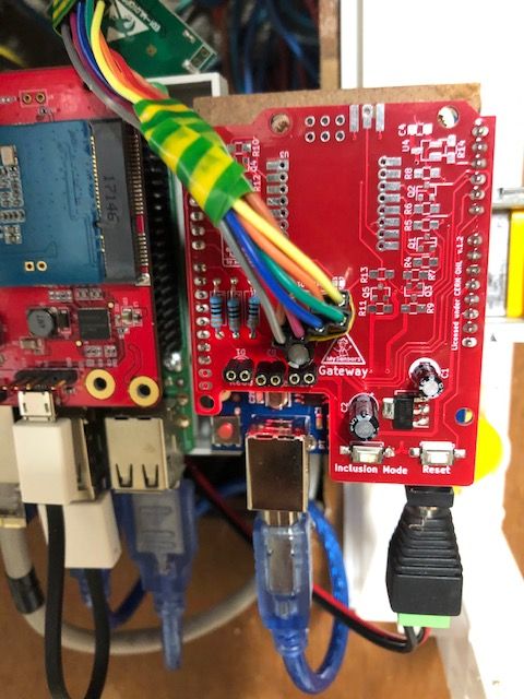
My gateaway is an esp8266 adafruit huzzah feather and my node arduino mini pro (8mhz 3v) using the psb of @sundberg84 ([here])(https://www.openhardware.io/view/389/EasyNewbie-PCB-RFM69-HWW-edition-for-MySensors)
I did not place any capacitor on the gateway, which is usb powered in my tests.
I will try to connect a decoupling capacitor like explained here like 47uF
Well, i've swiched all my sensors from nRF24 to RFM69 for longer range
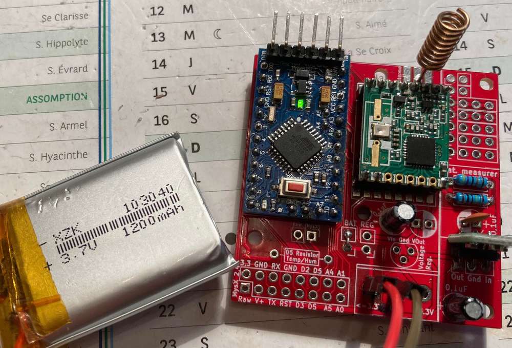
Hi all, for the sake of beginners like myself and to get advice on it, here is the code i have done to measure the battery of my sensors
based on @sundberg84 here: EasyNewbie-PCB-for-MySensors and articles i've read here
Please provide advice on how to manage switching analogReference()
Here is the class definition:
class MyBM {
  public:
    MyBM();
    MyBM(const float _VMIN, const float _VMAX);
    void setup(void);
    void MeasureBattery(void); //The battery calculations
  private:
    void burnreadings(void);
    float VBAT_PER_BITS;
    float VMIN;                          //  Vmin (radio Min Volt)=1.9V (564v)
    float VMAX;                          //  Vmax = (2xAA bat)=3.0V (892v)
    int batteryPcnt = 0;                 // Calc value for battery %
    int batLoop = 0;                     // Loop to help calc average
    int batArray[3];                     // Array to store value for average calc.
    unsigned int BATTERY_SENSE_PIN = A0; // select the input pin for the battery sense point
    int sValue;
    float Vbat;
};
You can change the values in the constructor MyBM() ; by default it is the resistors 1M and 470k for EasyPCB.
Following advice found on stackoverflow, i make 8 readings in burnreadings() when switching from analogReference(INTERNAL) to analogReference(DEFAULT) back & forth
MyBM::MyBM() {
  this->VMIN= 2.0 ;                   //  Vmin (radio Min Volt)=1.9V (564v)
  this->VMAX= 3.3;                    //  Vmax = (2xAA bat)=3.0V (892v)
  this->VBAT_PER_BITS= (1470/470)*(1.1/1024);
}

MyBM::MyBM(const float _VMIN, const float _VMAX) {
  MyBM();
  this->VMIN= _VMIN;
  this->VMAX= _VMAX;
}

void MyBM::burnreadings(void)
{
  for (int i = 0; i < 8; i++)
  {
    analogRead(BATTERY_SENSE_PIN);
  }
}

void MyBM::setup(void) {
  //=========================
  // BATTERY MEASURER

  //DEFAULT: the default analog reference of 5 volts (on 5V Arduino boards) or 3.3 volts (on 3.3V Arduino boards)
  //INTERNAL: an built-in reference, equal to 1.1 volts on the ATmega168 or ATmega328 and 2.56 volts on the ATmega8 (not available on the Arduino Mega)
  //EXTERNAL: the voltage applied to the AREF pin (0 to 5V only) is used as the reference.

  analogReference(INTERNAL);    // set the ADC reference to 1.1V
  burnreadings();            // make 8 readings but don't use them
  delay(10);                    // idle some time

  //Battery inital calc
  DPR("With Battery VMax (100%) = "); DPR(VMAX); DPR("volts and Vmin (0%) = "); DPR(VMIN); DPRLN(" volts");
  DPR("Battery Percent 25%/50%/75% calculates to: "); DPR(((VMAX - VMIN) / 4) + VMIN); DPR("/"); DPR(((VMAX - VMIN) / 2) + VMIN); DPR("/"); DPRLN(VMAX - ((VMAX - VMIN) / 4));
  sValue = analogRead(BATTERY_SENSE_PIN);
  DPR("Batterysens :"); DPRLN(sValue);
  Vbat  = sValue * VBAT_PER_BITS;
  batteryPcnt = static_cast<int>(((Vbat - VMIN) / (VMAX - VMIN)) * 100.);
  DPR("Current battery are measured to (please confirm!): "); DPR(batteryPcnt); DPR(" % - Or "); DPRLN(Vbat); DPRLN(" Volts");

  analogReference(DEFAULT);     // set the ADC reference back to internal
  burnreadings();            // make 8 readings but don't use them
  delay(10);                    // idle again

  //=========================
}

void MyBM::MeasureBattery() {
  analogReference(INTERNAL);    // set the ADC reference to 1.1V
  burnreadings();            // make 8 readings but don't use them
  delay(10);                    // idle some time

  // Battery monitoring reading
  sValue = analogRead(BATTERY_SENSE_PIN);
  DPR("Batterysens :"); DPRLN(sValue);
  //delay(500);

  // Calculate the battery in %
  Vbat  = sValue * VBAT_PER_BITS;
  batteryPcnt = static_cast<int>(((Vbat - VMIN) / (VMAX - VMIN)) * 100.);

  DPR("Battery percent: "); DPR(batteryPcnt); DPR(" %"); DPR("Battery Voltage: "); DPR(Vbat); DPRLN(" Volts");

  // Add it to array so we get an average of 3 (3x20min)
  batArray[batLoop] = batteryPcnt;

  if (batLoop > 2) {
    batteryPcnt = (batArray[0] + batArray[1] + batArray[2]);
    batteryPcnt = batteryPcnt / 3;

    if (batteryPcnt > 100) {
      batteryPcnt = 100;
    }
    DPR("Battery Average (Send): "); DPR(batteryPcnt); DPRLN(" %");
    sendBatteryLevel(batteryPcnt);
    batLoop = 0;
  }
  else
  {
    batLoop++;
  }

  analogReference(DEFAULT);     // set the ADC reference back to internal
  burnreadings();            // make 8 readings but don't use them
  delay(10);                    // idle again
}
Here is how i use it with a sensor that manages both interrupts and a sensor-specific timeout
// sdj is an object representing the sensor
MyBM bm;

void setup()
{
  sdj.setup();
  bm.setup();
}

void loop()
{
  if (tripped==0) {
    the_switch= sdj.get();
  } else if (tripped==MY_WAKE_UP_BY_TIMER) {
    if (sdj.wait_next()) {
      // timeout needs to do something for the sensor
      sdj.resetCode();
    } else {
    // timeout , nothing occured for sensor
    bm.MeasureBattery();
    }
  }

  // Sleep until something happens with the sensor or timeout
  tripped= sdj.sleep(WAIT_LOOP);
}
@mfalkvidd thank you for your help.
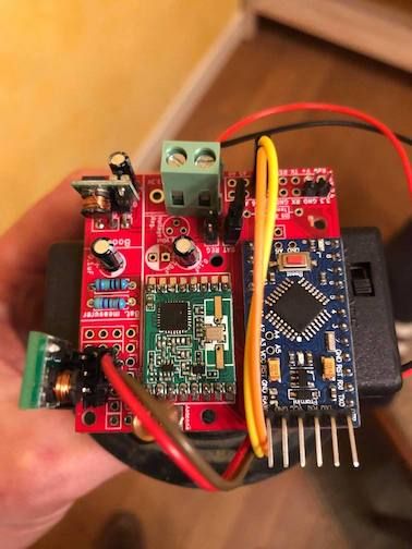
The node is a EasyNewbie-PCB-for-MySensors thanks to @sundberg84 in battery mode
Maybe i have a noise problem: i did not set the "BAT" jumper because my battery might be a bit to powerfull (3.7-4V) a little above what the radio may be able to receive.
Thank you @sundberg84 !
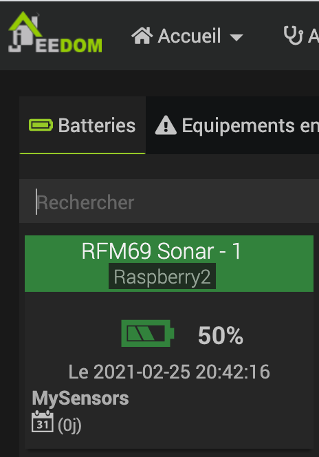
Well the node's been working for a whole day without loosing any message, and it reports its battery so everything seems fine.
By the way, i have my first RFm69 node based on easyPCB now working :-) (a sonar to measure fuel tank) connected to the gateway of @Gerator : works great
Hello @Emmanuel-Abraham , i've never used this pulse meter sensor.
as far as i can see, it's sending 3 different values to the gateaway:
flow value : send(flowMsg.set(flow, 2));
pulse count : send(lastCounterMsg.set(pulseCount));
volume : send(volumeMsg.set(volume, 3));
so if you want to send say the flow value to another node, let's say node 34
you should
flowMsg.setDestination(34);
and you have to add the
void receive(const MyMessage &message)
{
}
function in the code of your node n°34
@Emmanuel-Abraham sorry but i’m not sure i understand what you want to achieve.
i think you already have a working water pulse sensor but can you explain what you want to do ? why another node ? what do you want this node to do ? what data do you want to send to the node ?
what is your programming knowledge ?