Navigation

    • Register
    • Login
    • OpenHardware.io
    • Categories
    • Recent
    • Tags
    • Popular
    1. Home
    2. karl261
    3. Best
    • Profile
    • Following
    • Followers
    • Topics
    • Posts
    • Best
    • Groups

    Best posts made by karl261

    • RE: Is it possible to run more than one pin to an interrupt for sleep/wake purposes?

      @mfalkvidd Cool stuff, thanks!

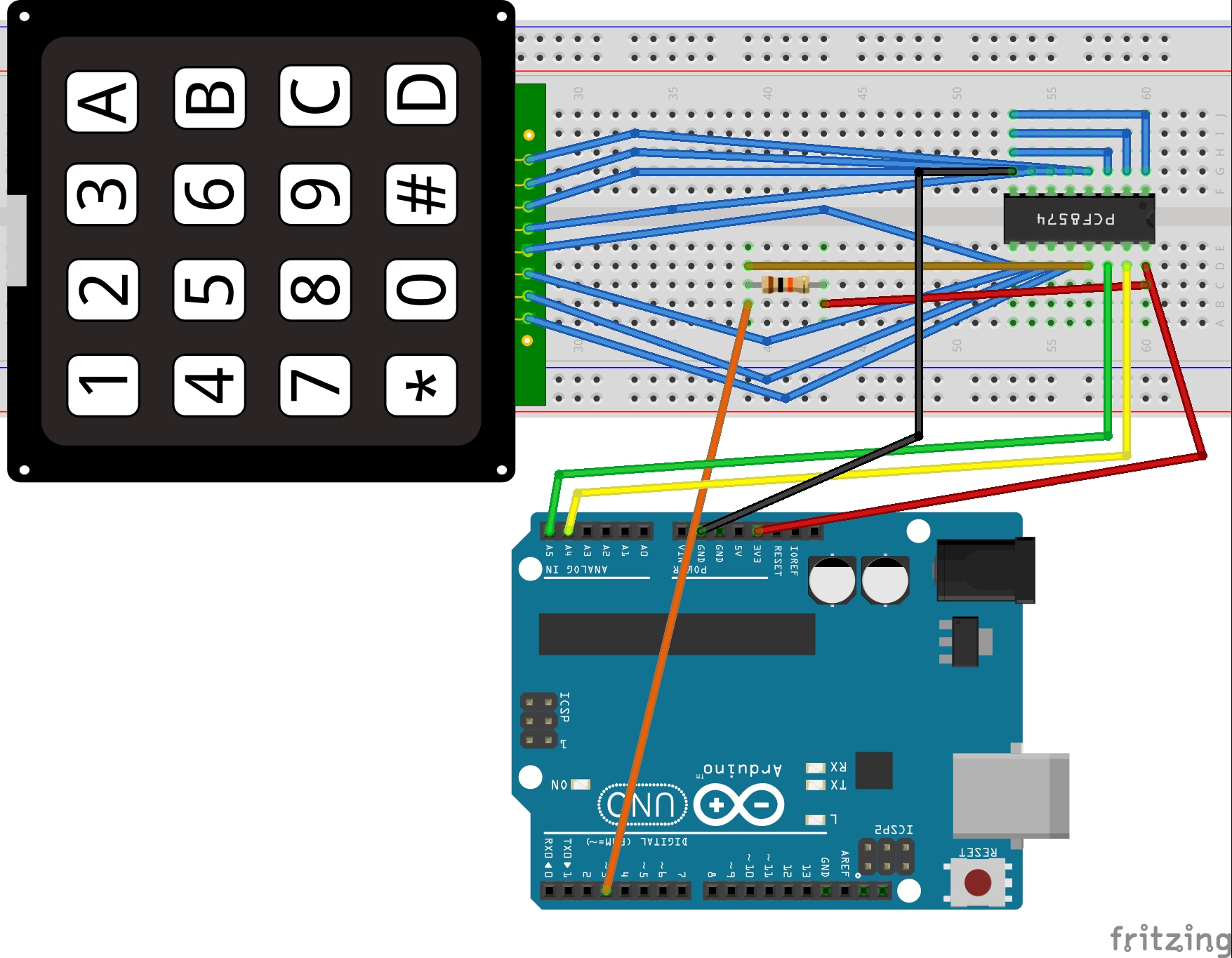
      @AWI Here you go. What a chaos... Sorry. 🙂 I thought of a setup like this. But the interrupt pin of the pcf is not doing anything. Maybe I need another chip?

      The resistor is 10kOhm.

      NRF is also connected. And working.

      The sketch is not ready, but the keyboard works on the serial line.

      0_1474716234250_Untitled Sketch_Steckplatine.jpg

      #include <Wire.h>
      #include <Keypad_I2C.h>
      #include <Keypad.h>
      #define I2CADDR 0x38
      
      #define MY_DEBUG
      #define MY_RADIO_NRF24
      #define MY_NODE_ID 8
      
      
      #include <MySensors.h>
      #include <SPI.h>
      
      
      unsigned long SLEEP_TIME = 0; // Sleep time between reports (in milliseconds)
      #define DIGITAL_INPUT_SENSOR 3   // The digital input you attached your motion sensor.  (Only 2 and 3 generates interrupt!)
      #define CHILD_ID 1   // Id of the sensor child
      
      const byte ROWS = 4; //four rows
      const byte COLS = 4; //three columns
      char keys[ROWS][COLS] = {
        {'1','2','3','A'},
        {'4','5','6','B'},
        {'7','8','9','C'},
        {'*','0','#','D'}
      };
      
      // Digitran keypad, bit numbers of PCF8574 i/o port
      byte rowPins[ROWS] = {0, 1, 2, 3}; //connect to the row pinouts of the keypad
      byte colPins[COLS] = {4, 5, 6, 7}; //connect to the column pinouts of the keypad
      
      Keypad_I2C kpd( makeKeymap(keys), rowPins, colPins, ROWS, COLS, I2CADDR, PCF8574 );
      
      void setup(){
          Wire.begin( );
          kpd.begin( makeKeymap(keys) );
      //    Serial.begin(9600);
          Serial.println( "start" );
          pinMode(DIGITAL_INPUT_SENSOR, INPUT);      // sets the motion sensor digital pin as input
      }
      
      void loop(){
      
          Serial.println("Waking up");
      
          char key = kpd.getKey();
          
          if (key){
          Serial.println(key);
          }
      
          Serial.println("Good Night");
          delay(100);
          sleep(digitalPinToInterrupt(DIGITAL_INPUT_SENSOR), FALLING, SLEEP_TIME);
      }
      
      posted in Troubleshooting
      karl261
      karl261
    • RE: nRf24L01+ connection quality meter

      For those who need and don't have a display like me, here is my sketch version for output to the serial console. So what I do is, I run around with a laptop connected to the node and watch the serial console, or, I just move around with a tablet and the node. The tablet is connected to my raspi and I watch the output of my gw on the pi using picocom. Picocom handles very well the missing line feeds in the output. The gw output is also very informative, there are no statistics, but still I see when stuff fails...

      Thanks for the cool sketch @AWI!

      /*
       PROJECT: MySensors / Quality of radio transmission 
       PROGRAMMER: AWI (MySensors libraries)
       DATE: 20160529/ last update: 20160530
       FILE: AWI_Send.ino
       LICENSE: Public domain
      
       Hardware: ATMega328p board w/ NRF24l01
          and MySensors 2.0
          
      Special:
          
          
      Summary:
          Sends a radio message with counter each  x time to determine fault ratio with receiver
      Remarks:
          Fixed node-id & communication channel to other fixed node
          
      Change log:
      20160530 - added moving average on fail/ miss count, update to 2.0
      */
      
      
      //****  MySensors *****
      // Enable debug prints to serial monitor
      #define MY_DEBUG 
      #define MY_RADIO_NRF24                                  // Enable and select radio type attached
      //#define MY_RF24_CHANNEL 80                                // radio channel, default = 76
      // MIN, LOW, HIGH, MAX
      #define MY_RF24_PA_LEVEL RF24_PA_LOW
      
      #define MY_NODE_ID 250
      #define NODE_TXT "Q 250"                                // Text to add to sensor name
      
      #define MY_PARENT_NODE_ID 99                          // fixed parent to controller when 0 (else comment out = AUTO)
      #define MY_PARENT_NODE_IS_STATIC
      #define MY_BAUD_RATE 9600
      
      
      // #define MY_RF24_CE_PIN 7                             // Ceech board, 3.3v (7,8)  (pin default 9,10)
      // #define MY_RF24_CS_PIN 8
      #define DESTINATION_NODE 0                              // receiving fixed node id (default 0 = gateway)
      
      #include <SPI.h>
      #include <MySensors.h>  
      
      
      // helpers
      #define LOCAL_DEBUG
      
      #ifdef LOCAL_DEBUG
      #define Sprint(a) (Serial.print(a))                     // macro as substitute for print, enable if no print wanted
      #define Sprintln(a) (Serial.println(a))                 // macro as substitute for println
      #else
      #define Sprint(a)                                       // enable if no print wanted -or- 
      #define Sprintln(a)                                     // enable if no print wanted
      #endif
      
      
      // MySensors sensor
      #define counterChild 0
      
      // send constants and variables
      int messageCounter = 0 ; 
      const int messageCounterMax = 100 ;                     // maximum message counter value 
      const unsigned counterUpdateDelay = 500 ;               // send every x ms and sleep in between
      
      // receive constants and variables
      boolean failStore[messageCounterMax] ;                  // moving average stores & pointers
      int failStorePointer = 0 ;
      boolean missedStore[messageCounterMax] ;
      int missedStorePointer = 0 ;
      int newMessage = 0 ;
      int lastMessage = -1 ;
      int missedMessageCounter = 0 ;                          // total number of messages in range (messageCounterMax)
      int failMessageCounter = 0 ;                            // total number of messages in range (messageCounterMax)
      uint8_t parent = 0 ;                                    // parent node-id 
      
      
      // standard messages
      MyMessage counterMsg(counterChild, V_PERCENTAGE);       // Send value
      
      
      void setup() {
      
          for(int i= 0 ; i <  messageCounterMax ; i++){       // init stores for moving averages
              failStore[i] = true ;
              missedStore[i] = true ;
          }
          missedStorePointer = failStorePointer = 0 ;
          delay(1000);
      }
      
      void presentation(){
      // MySensors
          present(counterChild, S_DIMMER, "Quality counter " NODE_TXT) ;  // counter uses percentage from dimmer value
      }
      
      
      void loop() {
          // Sprint("count:") ; Sprintln(messageCounter) ;
          Sprint("Parent: "); Sprint(parent); Sprint("       Fail "); Sprint(failMessageCounter); Sprint("   "); Sprint(getCount(failStore, messageCounterMax)); Sprintln("%");
          Sprint("Destination: "); Sprint(DESTINATION_NODE); Sprint("  Miss "); Sprint(missedMessageCounter); Sprint("   "); Sprint(getCount(missedStore, messageCounterMax)); Sprintln("%");
      
      
          missedStore[failStorePointer] = false  ;            // set slot to false (ack message needs to set) ; 
          boolean succes = failStore[failStorePointer] = send(counterMsg.setDestination(DESTINATION_NODE).set(failStorePointer), true);  // send to destination with ack
          if (!succes){
              failMessageCounter++ ; 
              Sprint("Fail on message: ") ; Sprint(failStorePointer) ;
              Sprint(" # ") ; Sprintln(failMessageCounter);
          }
          failStorePointer++ ;
          if(failStorePointer >= messageCounterMax){
              failStorePointer =  0   ;                       // wrap counter
          }
          parent = getParentNodeId();                         // get the parent node (0 = gateway)
          wait(counterUpdateDelay) ;                          // wait for things to settle and ack's to arrive
      }
      
      void receive(const MyMessage &message) {                // Expect few types of messages from controller
          newMessage = message.getInt();                      // get received value
          switch (message.type){
              case V_PERCENTAGE:
                  missedStore[newMessage] = true ;            // set corresponding flag to received.
                  if (newMessage > lastMessage){              // number of messages missed from lastMessage (kind of, faulty at wrap)
                      Sprint("Missed messages: ") ; Sprintln( newMessage - lastMessage - 1) ;
                      missedMessageCounter += newMessage - lastMessage - 1 ;
                  }
                  lastMessage = newMessage ;
                  break ;
              default: break ;
          }
      }
      
      
      // calculate number of false values in array 
      // takes a lot of time, but who cares...
      int getCount(boolean countArray[], int size){
          int falseCount = 0 ;
          for (int i = 0 ; i < size ; i++){
              falseCount += countArray[i]?0:1 ;
          }
          return falseCount ;
      }
      
      posted in My Project
      karl261
      karl261
    • RE: Raspberry uninteruptable power suppy

      @mfalkvidd No no, those are 10 F caps 2.3 V each. If you connect them in series you get a 3.33 F and 6.9 V Supercap.

      posted in Hardware
      karl261
      karl261
    • RE: Battery sensor and re-connecting to gateway

      Ok, thanks a lot. It is clear now. I will add some code and try. Later in 2.0.1 I can just remove this code...

      Question: the six failed transmissions: do they need to be consecutive? Or does it just count to six over time?

      posted in Troubleshooting
      karl261
      karl261
    • RE: Raspberry uninteruptable power suppy

      My UPS is working fine now for the past several months. My current setup is like this:

      AC -- Power suppply power bank -- power bank -- supercaps -- voltage regulator 5V -- raspi.

      The supercaps are needd because when the powerbank switches there is a short power interruption. The supercaps are buffering this.

      The 5V voltage regulator is needed, because when the power bank is charging and discharging at the same time its output voltage drops to 4.6 V or so. The voltage regulator keeps this at 5 V at all times.

      posted in Hardware
      karl261
      karl261
    • RE: Battery sensor and re-connecting to gateway

      Another question:
      Woudn't it be better to do something like this

      while(!isTransportOK()){
         wait(5000); // transport is not operational, allow the transport layer to fix this
         } 
      sleep(SLEEP_TIME);  // transport is OK, node can sleep
      

      or doesn't this bring anything?

      posted in Troubleshooting
      karl261
      karl261
    • RE: Battery sensor and re-connecting to gateway

      Wow, This is so cool. This probably solves all my problems from the past year.

      It just happened: I had a node connected to the gateway and brought it far away. It lost the connection to the gateway. I switched on a repeater node halfway. The node reconnected to the gateway via the repeater node.

      I can't believe it!

      posted in Troubleshooting
      karl261
      karl261
    • RE: Is it possible to run more than one pin to an interrupt for sleep/wake purposes?

      @AWI Finally:

      Yes, it works as expected. 4 pins are 0 V and 4 pins are 3.3 V. The chip is using 2.5 uA.

      I had to change a little bit the library, it did not compile and was slightly outdated, also the function we wanted to use was private, but I just did the changes in the library.

      I also needed to update to the latest arduino from 1.6.5 to 1.6.12, because i got an error: collect2.exe: error: ld returned 5 exit status. Now it works.

      Where do we go from here?

      posted in Troubleshooting
      karl261
      karl261