Navigation

    • Register
    • Login
    • OpenHardware.io
    • Categories
    • Recent
    • Tags
    • Popular
    1. Home
    2. Larson
    3. Posts
    • Profile
    • Following
    • Followers
    • Topics
    • Posts
    • Best
    • Groups

    Posts made by Larson

    • RE: Most reliable "best" radio

      It has been a long time but I’ve learned a few things that I wanted to share.

      1. This library of information (Thank you NeverDie and others) has been so helpful in my hobby developments.
      2. Software Defined Radios for signal analysis. With the help of Andreas Spiess explanation of IQ transformations, I learned about Software Defined Radios and I bought one (RTL-SDR). Using this I can clearly discriminate between effective 433 MHz transmitters and bad ones. Not only is the signal density displayed on the software (SDR#) but so is the frequency.
      3. Power Profiler Kit II has been indispensable in watching power usage and seeing into the details of the radio transmission. In effect this thing has saved me from buying an oscilloscope for my simple little bench.
      4. Tonight, I saw this video: https://www.youtube.com/watch?v=Z9nycymUd-I It describes common PCB errors. It is too advanced for me, but I did pick-up a few ideas about ground planes (tip #6 from the video).

      I hope this is of some value for folks.

      posted in General Discussion
      Larson
      Larson
    • RE: Most reliable "best" radio

      @NeverDie said in Most reliable "best" radio:

      What all does the elder care entail? If it's just supervision, maybe you can provide it using your automation skills.

      Thanks for asking. Yea, I thought of assigning a robot to the task of caring for my mother, but then I would be cast to the dungeon of my own making. Broken-hip, surgery, Rehab, Discharge - it is complicated and demanding. Fortunately we have skilled nursing and CNA's to do the bulk of the hard work. But getting mom's 'extended' taxes done, pain management intervention, arranging for PT, OT, Surgeon follow-up, rehab facility discharge, hemotologists, PCP's and where to land... it is a full time job. And then there is emotional support visits for the patient, my mom, while stress among sibilings and spouses becomes damaging. We all live too long.

      Yea, programming radios is my relief: develop, test, then correct. Far less human, and far more certain and way more fun. And when you are done for the day... you simply go to sleep. Sweet!

      I've been rereading this thread this evening. I'm glad for the record as I can relearn - even from myslef. So many great ideas that need further work by me. My 433 ASK transmitters are now controlled by 328P chips because the transmit times can be limited to 200 mS at about 6mA. I know, some of your radios can transmit faster but I'm just now divorcing my HT12E and HT12D chips and that is going to take time. Baby steps.

      On my new config (Barebones/SR501 motion detector/433 transmitor, the sleep current seems to be about 62 uA and that supports the SR501 motion detectors. That power dominates the energy profile of the device and is near the shelf-discharge of the battery - so it doesn't deserve much study. But the speed of the radio transmission does warrent further study since that is the high current period.

      posted in General Discussion
      Larson
      Larson
    • RE: Most reliable "best" radio

      @NeverDie said in Most reliable "best" radio:

      your garage remote most likely uses some kind of rolling code

      Yep, that's me. I figured the relay/repeater would echo the same rolling code in-and-out without having to figure it out. I've got enough earthly bound problems that are hard enough, so I'll take your advice and spend my festering curiosity on something more productive. But still ths PPKII is pretty danged cool.

      posted in General Discussion
      Larson
      Larson
    • RE: Most reliable "best" radio

      @NeverDie Excellent thinking on the signal detection. I think I'm going to build a garage door repeater. While the signal probably has some kind of encryption, maybe all I need to do is to repeat the same signal. But before I do that, I’ve got to return to the radio project you inspired. Elder-care has all of my time for now.
      My description above was a bit cryptic. What I marvel at is that I was only measuring the device power and didn’t know the transmitted code would be revealed in the power profile. But that makes sense now for most any battery powered transmitter including OOK, ASK protocols. As such your thought about detecting codes from TV remotes to garage doors would apply just by measuring the power battery power to the device. Effectively the PPKII becomes an O’scope.

      posted in General Discussion
      Larson
      Larson
    • RE: Most reliable "best" radio

      @NeverDie 5VTransmitterW501transmit5.png 
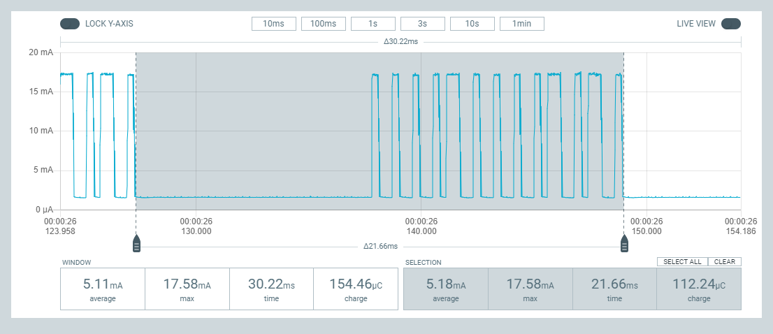
Here is a view of what the Power Profiler Kit II sampler (100,000 samples/second) could see. This is my 433 MHz radio/motion-detector rig picking up motion and sending a HT12E 12-bit address/data byte. Really fun to see that the ones and the zeros can be clearly seen in the FSK profile of the measured current of the device.

      posted in General Discussion
      Larson
      Larson
    • RE: Most reliable "best" radio

      @NeverDie Sorry for the slow response/question. Elder care still demands the day(s).

      Is the bounced signal physical? Or is it electronic reflection? I suppose it would be difficult to decipher.

      posted in General Discussion
      Larson
      Larson
    • RE: Most reliable "best" radio

      @NeverDie If I remember correctly, I was working on 433 MHz radios at the time - so a little slower rate. The sampling rate available though Audacity was way more than I needed to see the digital signal. At the time it was my first introduction to digital radio. And, in life so often, the first experience is the best. And it helped me realize that more advanced SW/HW like the PPKII depend on the same sampling of a signal. Pretty danged cool.

      posted in General Discussion
      Larson
      Larson
    • RE: Most reliable "best" radio

      @NeverDie A young Scott Harden taught me, via Youtube how to use a soundcard and Audacity recording SW as an o'scope. He would transmit a known preamble followed by a known pattern. I think this can be done in OSK, FSK, OOK. When the data is in Audacity, or an o'scope, then you can take your time to learn the timing of the transmitted and received signal. Seeing is believing, for me.

      posted in General Discussion
      Larson
      Larson
    • RE: Which PCB fab do you currently like the best?

      @NeverDie said in Which PCB fab do you currently like the best?:

      ... a project stalling out for want of a nail...

      That is poetic.

      I try to have some sympathy for my favorite (OSH_Park) and order multiple boards at once. Some pain of waiting is involved - only a week - and some waste is incurred by me as I correct my own errors before they ship. But I do like that they only ship three boards, instead of five, when I only need one. They must be annoyed by little-guys like me so I try to do my part with loyalty.

      posted in General Discussion
      Larson
      Larson
    • RE: Which PCB fab do you currently like the best?

      @NeverDie Here is a set I found on Amazon.

      Do you have a Dremel tool? I'll bet there are several sets of those. Dremel also has a nice jig that will hold the drill stationary and you can press down through it.

      Drilling the hole is one thing, connecting it to a trace could be a little tricky.

      [Edit: spelling errors.]

      posted in General Discussion
      Larson
      Larson
    • RE: Anyone using/tried the E28-2G4M27S 2.4Ghz LoRa SX1280 27dB module?

      @Larson Okay, No picture party yet. But, I did get a notification from Digikey that the Atmega328P-AN is back in stock for $3 each.

      posted in General Discussion
      Larson
      Larson
    • RE: Help! Is there *any* way to squelch either robocalls or India call center telephone attacks to my phone?

      @NeverDie Sorry for your pain. Something that has worked for me: once I detect a robo-call I leave the phone on but just walk away. I let them hang-up on me. Seems that they never call me back. Plus, sometimes I remember and block them. I like skywatch's idea of a accept-list rather than a block-list.

      Due to my elder-care responsibilities, I must answer all calls because I’ve made so many inquiries and dearly need help. Funny, my mom doesn’t have the volume of robo-calls that I get. Maybe the calls are related to activity? Burner phones with friendly-forwarding-filters might help?
      I would have called you to deliver this message, but …

      posted in General Discussion
      Larson
      Larson
    • RE: Some"ting" interesting...

      @ejlane said in Some"ting" interesting...:

      A little weird what we're willing to put up with, I guess. Though I also like the fact that with a record of how I drive, if there's ever an accident, it might also be possible to subpoena the data in my defense if really necessary. Or maybe that's just what I tell myself to help justify it?

      I'm in your camp. So while I attend the "speed limit" on I-205 east of Portland, I feel assured by the signs that say "Traffic laws enforced by videos". What a joke. In my last 35 days on that HWY, I've never seen even one enforcement action; people cruising well about 90 mph. In-vehicle recorders are my hope for redemption. How can the rest of the world be 'crazy' when I strain to be within-law. Some day I'll learn. I also paid all of my student loans and now feel sorry for myself.

      posted in General Discussion
      Larson
      Larson
    • RE: Most reliable "best" radio

      @NeverDie said in Most reliable "best" radio:

      not to be completely lost in the sands of time.

      Wish I could do more from my end. As long as this forum and the web exists... your library of knowledge will be of great value to me, and I presume, to others. I thank you!

      posted in General Discussion
      Larson
      Larson
    • RE: Most reliable "best" radio

      @NeverDie said in Most reliable "best" radio:

      two pin solution

      Sorry, sometimes when I reread what I wrote, I don't understand it either.

      My suggestion was to use only one radio and rotate different RF_PWR settings into the radio from the Atmega328p chip. That could be done by different means: 1. in the loop every 10 seconds or so for testing, or 2. by using GPIO pins defined as inputs, or 3. since we are talking radios, the power level could be transmitted to subject radio, read in code, and changed on the fly, or 4. any variety of other means (sensed light, temperature, vibration...)

      For example, I'm looking at your barebones board right now. The radio module I'm using (RFM69HCW) is mounted on the first 8 pins of the headers that include SPI connections. Neighboring pins A0 and A1 on the barebones header are open and could be jumpered to GND (logic 0) or VCC (logic 1). The program on the 328 could sense those pins and select one of 4 power levels in the RF_PWR setting per the table you show above.

      Hope that helps!

      posted in General Discussion
      Larson
      Larson
    • RE: Most reliable "best" radio

      @NeverDie said in Most reliable "best" radio:

      I suppose an alternate, non-elegant way to solve the problem would be to have an array of different nRF24L01 modules, each optimized for a different power level.

      Does the optimization mean different HW components with different RF_PWR settings? If the HW remains the same then one could incrementally change the RF_PWR level in the loop, right? Perhaps even by using two input pins one could control the RF_PWR level settings manually. The pins determine 00, 01, 10, or 11 and that gets fed to RF_PWR. That might be easier.

      posted in General Discussion
      Larson
      Larson
    • RE: Most reliable "best" radio

      @NeverDie You are building a library. I don’t have the time to consume/enjoy it now as I’m deep in eldercare. But for sure, I’m coming back to your wonderful library to learn more – just later. Don’t interpret my silence as… indifference.

      posted in General Discussion
      Larson
      Larson
    • RE: Most reliable "best" radio

      @NeverDie said in Most reliable "best" radio:

      The only upside is that it's sure to work.

      Very, very funny. Fell off my chair, funny. I had a similar experience with testing buzzers only I failed to recognize the upside/benefit. I ended up putting a switch on the speaker effect to maintain domestic tranquility.

      Yes, frequency user selection was my thought. It sounded like the mV range detection/optimization was too complicated. If the design gets close enough to the expected range, then punt to the user for fine tuning.

      Shells: Unless a resonant cavity is important, how about a simple tic-tac container with a pre-drilled speaker hole and some hot glue? Maybe a pezz container, if they make those any more? Even a Gatorade bottle cap filled with epoxy might work (use cellophane to cover/embed the mechanical parts of the speaker.) Failure has taught me many things, and this is one of them.

      posted in General Discussion
      Larson
      Larson
    • RE: Most reliable "best" radio

      @NeverDie said in Most reliable "best" radio:

      It would be nice if the system could self-calibrate the driving frequency to match the inherent resonance frequency of the buzzer.

      Perhaps an initialization User Interface selection? If the big picture is arranged and the region is only 5 Hz, then maybe a centeral default with an user option would be acceptable. Start slow, then rise in 0.25 Hz increments? If the user doesn't repond, then the default is mid-range. As in life, you can only help people so far. I think my mother tried to tell me that once.

      Caveat User (Emptor).

      posted in General Discussion
      Larson
      Larson
    • RE: Most reliable "best" radio

      @NeverDie Yep, that rocket stuff, and that dedication-to-task stuff, is pretty cool. Thanks for sharing - very inspirational.

      At a more modest level ... I received the Atmega 328P programming harness/clamp you recommended long ago. Nice. And your barebones board loaded with my RFM69HCW jig are working nicely. Also received: a bunch of your suggested radios and the carrying boards. Time, I need time. Can't thank you and @alphaHotel enough for the encouragement. I look forward to reporting if only to chronical for my own record and possible use for others.

      I hope it doesn't take me 7 years, but it may. Now all I need is a bunch of 48 hour days.

      posted in General Discussion
      Larson
      Larson
    • RE: Which PCB fab do you currently like the best?

      @NeverDie said in Which PCB fab do you currently like the best?:

      higher than quantity 5, then it seems to get kicked into a slower queue

      Well, you could play the game of ordering 4 separate orders if you wanted 20 boards. Seems silly... but if that is their system.... I always enjoy the minimum order so I can find my errors, then order the updates, and find my errors, then order the updates. Life is itterative.... until it isn't. What a blessing to have so much technology at such a little price. If you make a mistake you lose a little and remember the error.

      posted in General Discussion
      Larson
      Larson
    • RE: Which PCB fab do you currently like the best?

      @NeverDie Just for clarification, you are not asking about assembly, right?

      What a great thread (inquiry).

      I've relied on OSH Park for PCB manufacturing. Never have I found a mistake that was not of my own making. But for assembly, I'm really impressed with my one JLCPCB experience - and the parts availability (LCSC, I think). Their online CAD program (EasyEDA, I recall), was a small hurdle but easy enough.

      posted in General Discussion
      Larson
      Larson
    • RE: Anyone using/tried the E28-2G4M27S 2.4Ghz LoRa SX1280 27dB module?

      @NeverDie Yea, I think I knew you upversioned the silkscreen. I think I remember you commenting on it. Looks pretty. BUT in my effort to add to the community, since I typed it for my self for my V001 boards, I thought I'd share it incase there is anybody like me with V001.

      I like the V003 upgrades, specially that reset bypass via as discussed with @alphaHotel . Maybe I'll try it. I've got so much into my little V001's (yours actually) that I just can't give-em up. When I get the boards rigged up with radios, GPS (on the USART bus) and SD Card reader (on the SPI bus with a different CS), I'll shoot and send a picture in the spirit of a party!

      posted in General Discussion
      Larson
      Larson
    • RE: Anyone using/tried the E28-2G4M27S 2.4Ghz LoRa SX1280 27dB module?

      Here are the pin labels for the V001 barebones board for mounting on headers. The document I prepared for this wouldn't upload, but had nice lefthand/righthand orientations. This made it easier than having to open the CAD file everytime I needed to make connections.

      But here is what I did in MS Word:
      Turn on grid set spacing to 0.1"
      Turn on ruler
      Copy the below text
      Align to the right or left as you wish
      Font Calibri 5.5
      Verify spacing (14 pins = 1.4")
      Print

      I also made columns and multiple copies of the below with both alignments. I have two boards built. Maybe you have more. Hope it helps.

      GND
      D5
      D7
      D9
      D10/SS
      D11/MOSI
      D6
      D8
      A0
      A1
      VCC
      GND
      A5/SCL
      A4/SDA

      VCC
      D4
      D3
      D13/SCK
      D12/MISO
      D2/INTO
      A5/SCL
      A4/SDA
      A3
      A2
      VCC
      GND
      A5/SCL
      A4/SDA

      DTR
      RX TX
      TX RX
      VCC
      X
      GND

      [8/6/22 edit: reversed TX and RX as noted above - just incase someone has use for it]

      posted in General Discussion
      Larson
      Larson
    • RE: Most reliable "best" radio

      @NeverDie said in Most reliable "best" radio:

      because the resonate frequency seems to change

      Ahhh, I have something to offer. I remember way back when playing with piezo buzzers (something that is part of my mole project and in use today unfortunately) I remember incrementally changing the PWM frequency and duty cycle in the loop. I may be off base because I really don't understand what you are doing. But I remember that there is a sweet spot (resonant frequency, perhaps) where the sound would just pop. I've seen this in vocal quartets too (we are talking humans) when they hit some vibe some kind of God's amplifier gets invoked. It is really cool unless one has hyperaccousis, as I do. So I run an hide, but marvel at the science.

      @NeverDie said in Most reliable "best" radio:

      compare the design in the photo against another design which might use, say, a CR2477 or a CR2450 or a CR123A, etc. Probably somewhere someone has built a coincell simulator to answer these types of questions.

      During dev, I try to overpower with big batteries, or lines to sort it all out before playing with the smaller cells. Understand the demands first, then find the cell that can deliver. The LIR2450 seemed to deliver a good punch of curent that can carry radio transmission peaks of a ESP8266, 400uF caps helped. Nice thing is that you can control the timing of the peak audio with any other peak load... like a radio or something and prevent an overload.

      posted in General Discussion
      Larson
      Larson
    • RE: Most reliable "best" radio

      @NeverDie Soldier on, my friend. I love reading, but I've got nothing to add other than to report that I'm moving on to the radio portion of the barebones design. Maybe I do have something to add: I found that having JLCPCB/LCSC fabricate parts was really easy and not very expensive. The required EasyEDA design environment, I recall, linked LCSC inventory with JLCPCB quite seemlessly. As usual, for me, the learning curve took a long time. I think there were limits that wouldn't allow for exotic parts. That is not a problem for me and my simple ways. But shipping confusion did not exist as it was a combo thing. The minimum order of 5 and the single-sided fabrication were limitations that I could work with. Manually soldering SMD's is really hard and JLCPCB makes it so easy.

      posted in General Discussion
      Larson
      Larson
    • RE: Anyone using/tried the E28-2G4M27S 2.4Ghz LoRa SX1280 27dB module?

      @NeverDie said in Anyone using/tried the E28-2G4M27S 2.4Ghz LoRa SX1280 27dB module?:

      ...but I happen to think running from a crystal oscillator is generally a bad idea for a battery powered application...

      No, don't change the design. I think you have a platform with a specific low power intent - including the education of others (like me). Matter of fact, I've got several battery projects that would be FAR better by changing to the on-chip clock, and new core. And so far, we are only using the 8 MHz setting. In the MiniCore the choices go to 1 MHz.

      Back when I was... on PIC's... I bought 32 KHz crystals to minimize power. I just didn't know enough to use them and I still don't. But I'm working that direction and you have helped A BUNCH including you're idea of friends sitting around the table exchanging bits and bytes in a MISO/MOSI/SCK kind of way. I'm gathering that if you have control of the clock, you could have it all.

      Besides you, Kevin Darrah, and Felix @ LowPowerLabs have also made great contributions to the low-power idea. I just haven't dedicated enough energy, yet, to their efforts.

      16 MHz is impractically fast when so many designs just need low power.

      I wanna go back to school,
      DogWithA_Bone

      posted in General Discussion
      Larson
      Larson
    • RE: Bootloading a barebones arduino

      @NeverDie said in Bootloading a barebones arduino:

      You and a group of friends could sit around a table and pass bits and bytes to each other using an SPI communication protocol.

      Passing bits and bytes is probably more fun that sitting around a table and passing digs and barbs! I don't know: maybe my friends ARE binary!👼

      [Edit: I forgot to say anything about the content of your SPI protocol story. That was a great story; I feel badly for not thinking about the SPI connection at all. Now it is ingrained. ]

      posted in General Discussion
      Larson
      Larson
    • RE: Bootloading a barebones arduino

      @NeverDie Talking about virtual ports, HWFC, and chain breakage is way out of my experience. But I'm impressed that you are thinking at that level.

      On Baud Rate missmatch: Lacking an OScope, I suppose I could hook the PPKII to the TX of the barebones and transfere values of (2^8)-1, or 255, to see what the exact timing looks like. Serial.print(255, BIN) should do it, right? The datasheet tells me the max sampling speed of the PPKII is 100,000 S/s, so 9600 baud should show pretty clearly and enable me to fine tune what baud the MCU is generating. In a forum post I asked you what the trade-off is for using the internal crystal; you answered "accuracy". That is what got me thinking and looping on different baud rates. Serial Monitor was giving me 12#$, or the like, when I was expecting 1234 via Serial.print, so I knew it was close.

      How tight are the radios to baud support they get from the 328P? I would imagine the internal crystal baud rate is dependent on voltage. Maybe some formula exists in the 328P datasheet that allows for adapting this on the fly.

      posted in General Discussion
      Larson
      Larson
    • RE: Bootloading a barebones arduino

      @NeverDie said in Bootloading a barebones arduino:

      Something is amiss then.

      Probably true, and thank you for your commenting.

      I think all my USB-TTL converters are based on cheapo CH340G chips. But, to date, except for my blunders, I've not had a mismatch between the SW and FW baud rate that is so slight and I'm using the same wire length and converter as before(cheap & near, pluggable wire).

      I think I misstated the idea that that the bare bones "can't exactly keep up". The reverse is the case: the barebones MCU is faster than the IDE/USB-TTL combo. None-the-less, the timing is off so that Serial.print yeilds some ASCII characters instead of numbers. Incrementally changing the baud rate in the loop enabled me to test different rates. And what the serial monitor in the IDE thinks is 9600 baud, it is best expressed when the chip hits a baud rate of about 9000. Make sense? I'm imagining that the same is true if I were at 115,200, only relatively higher.

      In development, as I am, I always default to 9600 until I gain some confidence. Sometimes going slow is the source of my problem when chips are going so fast.

      posted in General Discussion
      Larson
      Larson
    • RE: Bootloading a barebones arduino

      @alphaHotel and @NeverDie

      It has been a long journey. Since being able to hack my barebones with an external clock onto the D20 and D21 nets, I’ve been able to talk to my barebones MCU in CMD window and Arduino IDE. Once talking, then I could bootload using internal crystal. But the major breakthrough today was trying to get the LEDs blinking. That brought me back to post 110 of https://forum.mysensors.org/topic/11917/anyone-using-tried-the-e28-2g4m27s-2-4ghz-lora-sx1280-27db-module/110?_=1659129333013. And here I re-learn that I’ve been on the wrong path along. After installing MCUDude in board manager, bootloading, and reprogramming (USART via USB-TTL) my LEDs are blinking away.

      But along the way I’ve learned a couple of things:

      1. The barebones Atmega 328P running without an external clock can’t exactly keep up with the IDE’s baud rate of 9600. Clock accuracy, I’m told, is the cost of using the low-power internal clock setting. So after some iterative looping, I’ve discovered that coding Serial.begin (8800) works on one board, and Serial.begin(9000) works on the other. Your chip will probably be different.
      2. To make the crystal hack noted above, I had unsoldered the two resistors on one of my barebones. On my second board, I simply held the crystal against the resistor base (facing D20, D21) while resetting fuses to internal clock setting; it worked.
      3. Before finding MCUDude, I had made edits to Board.txt file and copied one of the Pro Mini boards, renamed it, re-fused it, and that worked do. But as mentioned, the LED’s didn’t.

      I have been around the block a coupe of times with these boards and learned a bunch. Soon, I hope to actually mount a radio which originally looked like it would be fast work.

      Thank you to the contributors and readers of this post. For me, this forum has become a great source of discussion and documentation for my own record.

      posted in General Discussion
      Larson
      Larson
    • RE: Anyone using/tried the E28-2G4M27S 2.4Ghz LoRa SX1280 27dB module?

      @NeverDie said in Anyone using/tried the E28-2G4M27S 2.4Ghz LoRa SX1280 27dB module?:

      https://mcudude.github.io/MiniCore/package_MCUdude_MiniCore_index.json
      It's very easy to use. You can install it into the regular Arduino IDE, pick from among the MiniCore "boards" in the board manager, select the 8Mhz option and a few other obvious options, and then you're done with instalation. From that point on your code will automagically compile using MiniCore. Just to be sure, I gave it a try myself, and I'm now blinking a blue LED off of Ardino Pin 20. It works!

      I leave this post as a reminder to anyone else reading this thread. The MCUDude link and installation step is VERY important. To install in the Arduino IDE add the link in File/Preferences/Additional Board Manager URLs; go to Board Manager and filter on minicore, click on Install when MiniCore comes up. Next when selecting the MiniCore board, make sure to select Clock as Internal (8 MHz), or avrdude won't be able to find your board. I went with the other board manager defaults and ... WaLa... my new barebones board is blinking on both pins 20 and 21. Overlooking, or not remembering, this May 14 post has cost me several weeks. So if you build yourself a barebones, heed this post.

      posted in General Discussion
      Larson
      Larson
    • RE: Bootloading a barebones arduino

      @NeverDie said in Bootloading a barebones arduino:

      Honestly, you'll be surprised how easy it is to desolder a 328P if you use enough Chipquik.

      Before undoing my solder job on the barebones, I had to try again. I think my problem is solved. The short story is that the chips I bought are looking for a clock. (See This is a symptom of the target chip's clock not running.) Once I gave the chip a clock (thanks AlphaHotel for the insight of LED driver pins 20/21 hack) wala ... I'm now talking to the chip in CMD terminal. More to come.

      DogWithABone

      posted in General Discussion
      Larson
      Larson
    • RE: Bootloading a barebones arduino

      @NeverDie said in Bootloading a barebones arduino:

      Honestly, you'll be surprised how easy it is to desolder a 328P if you use enough Chipquik

      I"ll give it a go. What can I lose? Good excuse to use my Chipquick kit that arrived some time ago. I'm going to use my heavier iron. I won’t reinstall another 328P until the clam shell device arrives.

      posted in General Discussion
      Larson
      Larson
    • RE: Bootloading a barebones arduino

      @alphaHotel said in Bootloading a barebones arduino:

      Here's a pic I just did checking continuity between the MISO contact on the USBasp and the corresponding chip pin on a minimal setup 328P for reference.

      Motivated by your picture, today I breadboarded a 28 pin DIP 328 and bootloaded, programmed, and even set fuses successfully. That I could do that with my DIP, I think it is proven that I melted my barebones mounted 32 pin SMD. The fun part was using the default fuses and a 16 MHz crystal to make the LED blink (A5, pin 28). When removing the crystal, the blinking stopped. Perfect, it didn't work as expected. Fuses need to be reset. Using what you and @NeverDie taught me I could do this:
      First, I discovered the default settings using CMD window and the command: "avrdude -c USBasp -p m328p”
      That gives (E:FD, H:DA, L:FF).
      Second, I reset the existing fuses (seeking confirmation) with the command: "avrdude -c USBasp -p m328p -U lfuse:w:0xff:m -U hfuse:w:0xda:m -U efuse:w:0xfd:m"
      Third, I reset the fuses with "avrdude -c USBasp -p m328p -U lfuse:w:0xc2:m -U hfuse:w:0xdc:m -U efuse:w:0xff:m" based on the Gammon site @NeverDie sent me to.
      Then I pulled the crystal... and a thing of beauty ... it worked: led blinking, as expected.

      This is proof, to me, that the barebones solder job I did cooked the chip.

      I leave this post if it is of use to others, and in gratitude.

      posted in General Discussion
      Larson
      Larson
    • RE: Bootloading a barebones arduino

      @OldSurferDude said in Bootloading a barebones arduino:

      ...you got me thinking...

      This forum is built for that.

      Thank you for posting and the link to Arduino Bootloaders. I read that again. In summary of my reading, and in my own words: Bootloaders are the gravel under pavement. So I pose this as a question: If one uses "Sketch/Upload Using Programmer" it will load the program without the bootloader, right? Is that your understanding? Kind of like all pavement, no gravel.

      Over several of these exercises bootloading and programming with ICSP's using the Arduino IDE I've noticed that once a program is loaded with the ICSP using "Sketch/Upload Using Programmer", no further USB-TTL (USART) programming can occur until "Tools/Burn Bootloader" is subsequently executed. So in my limited experience, the bootloader is the gateway to normal USART programming. Too many words... I know. But the nice thing about the link you provide is that the Bootloader program is only 512 bytes. So one shouldn't fret over economizing over space.

      @OldSurferDude said in Bootloading a barebones arduino:

      ...skill and experience...

      I assume the skill that is required to remove the bootloaded 328P's from the Nano is a higher challenge. Soldering a new chip, as I did, has to be easy-peasy compared to removing and resoldering an existing chip. As it was, I think I killed my new chips because of the soldering & bridge removal. More on that to come in my next post.

      @OldSurferDude said in Bootloading a barebones arduino:

      ...pretty awesome and I wish you success

      Kind of you. At this point, I'm kind of a dog with a bone. Given the contributions of NeverDie, AlphaHotel and others, I just have to press on or all the time & effort is for not. Perhaps the dialog is of use to others.

      posted in General Discussion
      Larson
      Larson
    • RE: Most reliable "best" radio

      @NeverDie said in Most reliable "best" radio:

      Exactly which type of guitar strings do you buy that work the best? i.e. do you try to match the castellation diameter with the diameter of the string?

      The brand is D’addario, I think. It measures 22 mills, and yes, I was trying to fit the diameter of the castellation. Looking online I see there are many different types, but I just asked for high carbon steel at the local music store.

      @NeverDie said in Most reliable "best" radio:

      Also, regarding your layout for them on the PCB, how do you decide where to position them? i.e. do you use a formula or something, or do you eyeball it and take a WAG?

      It was a calculated WAG, but it worked. I wanted the rows of vias to be about 10 to 20 mills closer than the radio’s two rows of castellated pockets. The distance between the radio's castellated surfaces measures 616.5 mills. The distance between the via centers is 622.0 mills. Subtracting the 23-mill hole diameter would result in the via surface-to-surface distance on the board of 599 mills. The 17.5 mill difference (616.5 - 599) means the radio would not be able to slide all the way to the bottom. When engaged, the radio slides down within 1/4 inch of the board while the springs tops splay outward slightly.

      @NeverDie said in Most reliable "best" radio:

      And how do you keep them perpendicular to your PCB while you solder them?

      You are asking all the right questions. Since OSH Park gave me 3 boards, I used one at each end of the wire. I think I used some blue-tac under the target board and maybe some blue-tack, or tape, to hold the place-holder board at the other end of the springs. Then I soldered top pads of the target board, flipped the assembly over, remove the target blue-tac, and soldered the bottom via surface.

      To do this again, I would add SMD pads on the bottom of the board that would give more soldered rigidity to the spring base. I also had some slight alignment problems as the vias are not exactly straight. It was my first KiCad project; thank you for encouraging me to try. KiCad probably has an alignment tool. The other change I might make is to cut the wires down to about 0.5-inch, or less. The existing 0.9-inch length was helpful for assembly and soldering access, but my fear is that each of these longer wires form a potential antenna. I wouldn't change any of the other dimensions.

      You are welcome to 'my' KiCad file based on your design. Is there somewhere that I can drop it. I can't do it here.

      posted in General Discussion
      Larson
      Larson
    • RE: Most reliable "best" radio

      @NeverDie said in Most reliable "best" radio:

      @alphaHotel Thanks for your post. It reminded me that for one-time programming, all one really needs is just the through-holes on the board. You can then bend the pins on a male header to create a kind of "weave" pattern, and that alone is enough to hold it into place during the programming, after which you can simply remove it. I've confirmed this works at 2.54mm pitch, and so I'll try it at 1.27mm pitch. I expect it should work well with that too.

      Those castellated notches of the RFM69XXX radios and ESP12 radios appealed to me as an opportunity to use springs in a different way. I think I talked about that in an earlier post. Well, I designed one based on NeverDie's radio boards and the picture below is how it turned out. For the springy things I used high-carbon-wire (guitar strings.) I had to cut the wire with a Dremel grinder because shears would bend the wire at the cut. The springs don't need to be nearly this long, though it does allow for a lot of flex when entering the jig at the top. At the pads on the board I used large via's (about 21 mills, I think) so that I could solder both sides of the board for rigidity. This would all for the rapid testing of dozens of radios if necessary.

      As you know, I am having trouble with bootloading so I haven't implemented the idea yet. But I'm really pleased at how the dimensions worked out and the spring tightness. I got this idea from looking at RJ45 connectors and thinking that I could do something like that.

      I tried a few pogo-pin designs for ESP programming, and they work... but not easily. This design is a snap. I think I left behind the design files.

      IMG_0012.JPG

      OSH_ParkImage.png

      posted in General Discussion
      Larson
      Larson
    • RE: Bootloading a barebones arduino

      @alphaHotel said in Bootloading a barebones arduino:

      I'd suggest putting this one aside for now and trying again (I'm assuming you have at least 2 other copies of V001 boards as OSHpark tends to sell them in 3-packs).

      Thanks again. I will put this aside for a while... eldercare calls anyway. I'm going to order V3 boards and maybe have them fabricated too. The last picture is of the second OSHPark board and second 328p. So I'm down to three 328p's.

      I am indebted to this community and I thank everyone for the gracious help.

      posted in General Discussion
      Larson
      Larson
    • RE: Bootloading a barebones arduino

      @alphaHotel said in Bootloading a barebones arduino:

      Also, take a close-up picture of the board/chip and post it here for us to see what you've got going on.

      Pictures are below. I should add that the ICSP 2x3 cable coloring is:
      Black - GND
      White - MOSI
      Red - VCC
      Brown - MISO
      Yellow - SCK
      Orange - RESET alligatored to bottom of switch.

      IMG_0001.JPG

      IMG_0003.JPG

      IMG_0004.JPG

      IMG_0005.JPG

      IMG_0006.JPG

      IMG_0008.JPG

      posted in General Discussion
      Larson
      Larson
    • RE: Bootloading a barebones arduino

      @NeverDie said in Bootloading a barebones arduino:

      I just had an idea that might help you.

      Thanks for the thoughts. I have pretty direct access to the 328p's reset pin now by alligatoring on to the 328p's side of the reset switch. But... If I needed to connect DTR to Reset I think I would leave the capacitor in place and jumper from Reset to DTR. Soldering those capacitors into place is something I really don't want to relive.

      @NeverDie said in Bootloading a barebones arduino:

      Actually, the same would hold true on an Arduino Pro Mini,

      For a known good platform, I've been using the Nano because it has the ICSP direct access to reset. But I see where you were going with the ProMini. Looking at the schematic you attached, I see that direct access to reset exists on JP7, pin 10. That would do it, wouldn't it?

      posted in General Discussion
      Larson
      Larson
    • RE: Bootloading a barebones arduino

      @alphaHotel said in Bootloading a barebones arduino:

      I believe you got these 328p's from Aliexpress (or similar). Did the listing indicate whether there was a bootloader or not? Bare chips, should be factory set to operate on the internal 8MHz oscillator, so that shouldn't be the problem. How many did you buy?

      Thanks for your post. I bought 5 of these 328s's from https://www.aliexpress.com/item/3256802836313338.html?spm=a2g0o.order_detail.0.0.3f26f19cw3rLj0. Just reviewed the page and there is no mention of bootloader. I presume these are not bootloaded, but that wouldn't stop me from trying a good-old-fashioned Blink program via the USART port.

      I checked for continuity bridges on adjacent pins. I'll do that again for regional pins. Earlier I found that detected bridges were visually evident. I now look closely, then test. I can't check USBasp connections enough - I'll do that again. Dead chip? Well, it could be thermally abused given my caveman skill. Fuse settings? Manufactures probably have to make assumptions on this and the prevailing one would probably be for a 16 Mhz crystal.

      Sure, I'll take a picture and post. It is a rat's nest at the moment so I'm first going to solder on headers to make things clearer/cleaner to see.

      Thanks again for the abundant help!

      posted in General Discussion
      Larson
      Larson
    • RE: Bootloading a barebones arduino

      @OldSurferDude said in Bootloading a barebones arduino:

      I have programed Arduino Nano's using the Arduino IDE ISP function. I had some with an old boot loader and some I just needed a touch more space. The programmed Arduino's are functioning as expected, so I don't think there's a problem.

      I think I've read that Uploading Using Programmer will install your program, but NOT the bootloader so you end up with a little more room... but no bootloader for the next USART attempted reprogramming.

      @OldSurferDude said in Bootloading a barebones arduino:

      My question is, would this work to program a raw Atmega328p chip?

      Yes, I think that is the aim: turn one 328 into an ISP programmer so that it can 'burn' another 328 via the ICSP connectors. And by 'burn' I mean either the bootloader program, or any other program of your choosing.

      posted in General Discussion
      Larson
      Larson
    • RE: Bootloading a barebones arduino

      @NeverDie said in Bootloading a barebones arduino:

      For a "known good" starting point, you could pop the DIP atmega328p out of an arduino uno and practice burning your bootloader into that on a breadboard. If it gives you the same guff, then you know it's your procedure and not the chip that's at fault. Anyhow, as there's not really much that can go wrong, my WAG is that, based on @alphaHotel 's earlier comments requesting a reset-pin breakout (now baked into Version 3.0), it might have something to do with either the means or the assumptions under which your burner is accessing the reset pin.

      I've got some DIP 328's. Good Idea. I'll try that. Your V1 board has access to Reset. I used an alligator pin to clamp on to the mcu side of the reset switch. So far, I have connected that to the RST pin of the USBasp.

      posted in General Discussion
      Larson
      Larson
    • RE: Bootloading a barebones arduino

      @NeverDie said in Bootloading a barebones arduino:

      Myself, I burn the bootloader and fuses in one of those spring-steel clamshell chip holders:

      @NeverDie I just ordered one! Thanks. I didn't know these existed. Slick.

      posted in General Discussion
      Larson
      Larson
    • RE: Bootloading a barebones arduino

      This thread was opened to continue explore how to bootload a project that was giving me fits. The project is based on wonderful work of this thread by NeverDie. That thread explores the testing of many different radios all ridding piggy-back, one at time, on a custom barebones Arduino board using the Atmega328P chip. After building said barebones board, I am having difficulty getting the bootloader loaded on to the board. AlphaHotel has very generously offered some help in a private chat session. At this moment we have been trying to find the right driver for my 7-year-old USBasp V2.0 LC Technology programmer. Bootloaders are typically, I think, installed onto new 328 chips using the SPI interface that the USBasp, as opposed to using USBTTL converters using USART interface.

      There is some back story to the help session I’ve already received from AlphaHotel. I’m not going to discuss that history except to say that we tried to install a USB driver using zadig-2.7.exe. The driver we focused on was libusb-win32 driver. I think the challenge here is to get older hardware, such as the USBasp (x32), to work on newer (x64) machines like my newish Windows 10. Our efforts on loading the libusb-win32 driver did not work.
      Our newer effort focused on using libusbK as a driver. I found more success with that but no success yet on the barebones bootloader install. So from here, I’ll expose our help session in the form of a thread so that we can communicate and use PIC attachments while documenting the process for others.

      Using the libusbK I was able to get some success bootloading. The general idea was to update the USBasp driver, then to test the new driver by bootloading then programming a Nano. If that works, then try to do the same on the barebones board. Two SW methods of bootloadings were used: 1. By using the Arduino IDE environment (Burn Bootloader) and 2. The Windows CMD (Command) application. Here is a summary of my progress with pictures of screens that display the progress.

      1. Zadig driver installation of libusbK. Success!
        1ZadigInstal.jpg

      2. After unplugging and replugging the USBasp from the computers USB port - Device manager result:
        2Device Manager.jpg

      3. Arduino IDE Test of loading Blink to a Nano using “Upload Using Programmer” using USBasp. Success!
        3BlinkSuccess.jpg

      4. Command prompt and response with Nano Still attached:
        Command: avrdude -p m328p -c usbasp
        Response:
        Reading | ################################################## | 100% 0.03s
        avrdude: Device signature = 0x1e950f (probably lgt8fx328p)
        avrdude: safemode: Fuses OK (E:FD, H:DA, L:FF)
        avrdude done. Thank you.
        Success!
        4CMD_Command_Response.jpg

      5. Further Arduino IDE Test of USBasp to “Burn Bootloader” to Nano
        Success!
        5DoneBurningBootloader.jpg

      6. Fuse Settings, as shown above (E:FD, H:DA, L:FF)
        Success!

      7. Extended test: Try to Burn Bootloader to NeverDie’s barebones board (328) using Arduino IDE. Fail.
        7BurnBootloaderToBareBonesFail.jpg

      8. Extended test: Try to burn bootloader to NeverDie’s barebonds board (328) using Avrdude. Fail.
        8BurnBootloaderWithAvrdudeFail.jpg
        Given these last two failures on multiple tries, I’m thinking that I may have toasted the Atmega328p in the process of my soldering and bridge unsoldering. This was my first attempt for such a tiny SMD Atmega328p. I am very sure that I got the right orientation. Or, it could be that the Atmega328p that I purchased came from the bottom of somebody’s barrel.

      I continue to work on this and will post results here.

      posted in General Discussion
      Larson
      Larson
    • RE: Most reliable "best" radio

      @alphaHotel Chat sent. My apologies to NeverDie for the distractions to a very fine thread.

      posted in General Discussion
      Larson
      Larson
    • RE: Most reliable "best" radio

      @alphaHotel Still working on getting my USBASP reprogrammed. After googling I found this site: https://www.electronics-lab.com/project/usbasp-firmware-update-guide. That program says to create a new programmer; I used a Nano and uploaded the ArduinoISP successfully. Next I combine the avrdude.conf, avrdude.exe, and the update hex file in one file as suggested. I used your latest release link to find the update hex file to be main.hex for the Atmega8 that lives on my USBASP. The readme files in your link lead me to that conclusion.
      After connecting everything together I enter “avrdude -C avrdude.conf -P COM9 -p m8 -c avrisp -b 19200 -U flash:w:usbasp.atmega8.main.hex:I” in the windows command line.

      I get these errors:
      avrdude: error at avrdude.conf:1133: programmer type jtagice3_updi not found
      avrdude: error reading system wide configuration file "avrdude.conf"

      I found jtagice3 in the config file to be a defined programmer. I feel that I’m close. Any ideas? I continue to work on it.

      posted in General Discussion
      Larson
      Larson
    • RE: Most reliable "best" radio

      @alphaHotel I'll try the firmware update. Thanks. I suspect my problem is the SCK speed. I get immediate failure. I don't think I can reach the fuses if the 'target' chip doesn't have a bootloader. Do I have that wrong? The wierd thing is that I used my USBasp to bootload an extra Nano I have on hand. That worked fine. On the bare bones board, I've double/triple checked the connections and I've rechecked the 328 chip for solder bridges & solid connections with pins. I have downloaded your recommended link. The 2011-05-28 Thomas Fischl Readme.txt file looks complicated. I'll see if I can manage that. Thanks again.

      posted in General Discussion
      Larson
      Larson
    • RE: Most reliable "best" radio

      @NeverDie said in Most reliable "best" radio:

      Anyhow, I meantion it because if you can find a programmer that does dance with Microchip Studio, it's a fairly easy interface to learn and to use. You just go to menu Tools....Device Programming... and it's all right there. Microchip Studio is free so if you want to preview what it might look like, just download it and give it a squiz. I don't actually use Microchip Studio for anything other than just this particular feature

      Thanks for another tip/reminder. I still have the Atmel Studio 7, Microchip Studio predecessor, loaded and I think that played a role for me in the past in this hurdle – you reminded me of that. I’ll give it another go. I remember the strength of AS7 was that one could debug code (see registers) a command at a time – pretty cool.

      posted in General Discussion
      Larson
      Larson
    • RE: Most reliable "best" radio

      @NeverDie Thanks for the tip. I went as far as dipping my solder wick in my new SRA Flus #135 (yes, your recommendation; thank you again). That may have been the trick because ... it worked! Actually, I didn’t dip it but smooged the stuff onto the wick using a toothpick as a trowel. Yea, it was a mess afterwards. I used a foil tray as an alcohol bath before cleaning with a toothbrush.

      My problem today is bootloading the brand new 328's with my old USBASP. The IDE says something about “cannot set SCK period” and then “initialization failed”. I’ve been here before and it just takes time to relearn. I made ReadMe notes but I can’t find them. I’ll try again tomorrow.

      posted in General Discussion
      Larson
      Larson
    • RE: Most reliable "best" radio

      @NeverDie Just checking in. I've received lots of different radios and built two of your bare-bones kits. Soldering the Atmega328P chips were easier than I thought – first time ever on pins that small. My MM showed many, many solder bridges existed. Solder-wick helped fix that. Hope I didn’t burn the chip.

      Before I start running tests on the different radio’s as you have, I’ve been getting a GPS functioning which has been fun. After collecting data around the perimeter of our small property, I figured out how to do a XYZ 3-D plot in Excel – not easy.

      In the GPS process I’ve been watching this video (https://www.youtube.com/watch?v=gtM832Z0ujE&t=219s ) and he has a conclusion that you might be interested in: locating the transmitting radio (nrf24L01) close to the MCU was limiting the packet/per/second performance, and limiting range. With this in mind, I hope to test your radio carrier boards on a Dupont wire extension raising it off the bare-bones board. Then test with and without and see how it does. Again, I’m hoping all that wire doesn’t inadvertently create unwanted antennae interference.

      But, obviously, I’m on the slow road still.

      posted in General Discussion
      Larson
      Larson
    • RE: Most reliable "best" radio

      @alphaHotel said in Most reliable "best" radio:

      I thought your turnaround time was decent compared to mine.

      My latest OSH Park order was 9 days inclusive (ordered 6/20/22, delivered on 6/28/22). I find that pretty remarkable. I've read, somewhere, that the timing is at risk of your position in the panel queue; if you are early on the panel, then it is slower. There is a “super swift” service from OSH for a charge. Free-shipping moves faster than I can, so I can wait. The price can't be beat and the quality is great (except for the errors that I make!!!)

      @NeverDie
      The silkscreen markings for the AA mount posts on your Test Platform V001 are on the right side for me. Mine arrived last week! Sure, the markings are on the reverse side, but once the batteries are installed, that side is invisible. I’m still fretting the moment when I need to solder the Atmega 328P chip.

      To follow-up on earlier posts: the speed of delivery from China has dramatically improved. Most of the orders I’ve place in early June have arrived. Even the hard-to-get Atmega 328P chips have arrived so I don’t have to desolder my old Nano’s or ProMini’s. And the Chinese packaging is efficient - less trash for my conscience. Digi-Key leaves me wondering how such little can arrive in a box that is so big. But... Digi-Key is so fast.

      posted in General Discussion
      Larson
      Larson
    • RE: Most reliable "best" radio

      @NeverDie

      Strikethrough
      [Would 15 mseconds be close enough?
      #include <LowPower.h>
      LowPower.powerDown(0, ADC_OFF, BOD_OFF); //0 gives SLEEP_15MS,] Strikethrough

      [Edit - Sorry - on rereading is see the objective is 1.6 mS not 16 mS. I like your Timer suggestions - that is what they are for.]

      posted in General Discussion
      Larson
      Larson
    • RE: Anyone using/tried the E28-2G4M27S 2.4Ghz LoRa SX1280 27dB module?

      @NeverDie You have a point. The TPL is also simpler.

      But bless the developer. Yes, I was trying to hype his product. I forgot to mention that doing this current test was really easy because this thing just worked... right out of the box (really, out of the anti-static bag.) Rarely have things work so quickly for me. Even the TPL required fumbling.

      So if sleeping is the objective and timing isn't really important, then the TPL it is. But if configuration settings, Bluetooth, ADC, I2C, SPI and timing are relevant, then the Trigboard is the way to go.

      posted in General Discussion
      Larson
      Larson
    • RE: Anyone using/tried the E28-2G4M27S 2.4Ghz LoRa SX1280 27dB module?

      @NeverDie Here is my report on the Kevin Darrah Trigboard (V8.1) as promised. Fundamentally, the power draw of this board is about as low as the TPL5110. His board ships with door monitoring firmware on it that is conducting some kind of polling every 320 mS, it appears. Between the polling the current draw is about 180 nA, per my PPKII. If one were to include the polling activity, then the average current is about 1.3 uA. A picture of this is below. If an alarm condition is achieved, the device makes an internet connection and broadcasts a message to third-party servers that will alert the user by phone/text/email. Of course, that takes time (between 2 to 3 seconds), and additional current.

      If you have 30 minutes, Kevin has a start-up video that is very informative. He makes the point that this board consumes a small fraction of what smoke detectors use. While the PPKII shows that the Trigboard has an equivalent sleep current, the Trigboard delivers the monitoring function for additional, though modest, current. As before, I find value in comparing these tiny currents to the expected shelf-life burn rate that is orders of magnitude (at least one) higher.

      This was my first exposure to ESP32’s. Kevin indicates that the performance of the ESP32 is better than the ESP8266. I like the idea of Bluetooth access for being able to configure devices, as Kevin shows, and for access to sensor data – especially in development & debugging. I have not reviewed his firmware that he generously has made available. His “Configurator” firmware looks to be a great example of how to build user menus to input variables. This looks like the new form of the older WiFi Manager libraries which have been very useful.

      PeakCloseLook2.png

      posted in General Discussion
      Larson
      Larson
    • RE: Most reliable "best" radio

      @NeverDie said in Most reliable "best" radio:

      CORRECTION: Earlier I said that Adafruit's TPL5110 breakout board appeared to use a 1M pulldown resistor on DONE. I remeasured today and that's wrong. It's actually a 10K resistor.

      Thanks for redirecting me to this thread. I think you were right on your original 1M Ohm assertion. Since I'm playing with my new TPL5110,s I took it on to make my own MM measurements. While my Harbor Freight MM might not be the most accurate instrument, I did show the resistance between DONE and GND to be 900 K'ish. Next, I got out the magnifying glass to spy the resistor in-line with said pins to have a marking of 1004. Google affirmed that that means 1 M ohm. So, your 5K, or 10K would be a big change – and if it comes at no cost for the quiescent current AND enables ESP action, then perfect!

      posted in General Discussion
      Larson
      Larson
    • RE: Anyone using/tried the E28-2G4M27S 2.4Ghz LoRa SX1280 27dB module?

      From the MySensors forum entry:

      @NeverDie said in Anyone using/tried the E28-2G4M27S 2.4Ghz LoRa SX1280 27dB module?:

      Hmmmm... Something's wrong then with Adafruit's design if it's 20uA. The chip itself consumes only 35na according to its datasheet:
      https://www.ti.com/lit/ds/symlink/tpl5110.pdf?ts=1652658923819&ref_url=https%3A%2F%2Fwww.google.com%2F

      My TPL5110's arrived and I hooked one up to the PPKII to take a look. Remember that Adafruit advertised a disappointing OFF-state current of 20 uA. Fortunately, I have found this not to be the case. Instead, my PPKII shows the off state to be 120 nA; picture attached. The load I used was an LED hooked up to a resistor and the PPK is supplied with 3.3V. As earlier discussed, I’ll next dig out the TrigBoards that Kevin Darrah sent me to see how they do.
      TPL5110_ShutDown.png

      posted in General Discussion
      Larson
      Larson
    • RE: Anyone using/tried the E28-2G4M27S 2.4Ghz LoRa SX1280 27dB module?

      @NeverDie and
      @alphaHotel

      Thanks for the links. I'm going for the silver (Ag)! The little that I remember from physics is that silver has high conductivity and low melting point. Perfect. Too bad it is so expensive.

      I have a few dental crowns that could be remelted and ...

      posted in General Discussion
      Larson
      Larson
    • RE: Most reliable "best" radio

      @NeverDie Yes, I think we are surfing the same wave. I'm thinking of a PCB mount that will recieve a perpendicular PCB board with double sided connectors like this: https://www.ebay.com/itm/122943051785?hash=item1c9ffa1809:g:daAAAOSwd4tTxdNW

      Maybe there is an application of these for the radio modules that have the single row SMD mounting pads? One would need to ignore the opposing connectors. Better yet, maybe there are radio boards (?) that could be designed to slot in... just thinking. The NRF24’s would require double-sided 1x4 board and receivers. That would be cool and compact.

      But then there is the ground-plane to think about?

      posted in General Discussion
      Larson
      Larson
    • RE: Most reliable "best" radio

      @NeverDie said in Most reliable "best" radio:

      Maybe @Larson 's idea of using zebra strips as connectors is more practical.

      I learned about zebra strips from you - thank you very much. I was unable to re-establish connections for an existing commercial products and I don't know why. My thought was that zebra strips were some technology and complex signaling that is beyond my capacity. The device is probably over 20 years old. Therefore, I would not recommend zebra strips because I don't know enough about them.

      This pic from your link is more telling of the capability of your referenced connectors. 9f5492d7-b994-4cd1-9d05-9c9769eeff88-image.png For now, I don't know why these are called edge-connectors. I thought edge-connectors were flat male blades with double-sided contacts that were fitted in sloted female gaps. The ones I think I've seen have an index slot for, I suspected, polarity protection and alignment. Maybe I've got this all wrong and they are called something else - like card connectors.

      posted in General Discussion
      Larson
      Larson
    • RE: Most reliable "best" radio

      @NeverDie said in Most reliable "best" radio:

      It must be something about the physics of buzzers that the thinnner they get in these small packages, the quieter they are.

      I'm thinking of speakers of the 1970's: the drivers, midrange and tweeters would be nothing without the cabinet boxes. Does that apply here? In the 2010's these "soundbars" come into the picture. But there is still a box involved. Yes, it is probably about the physics of sonics... I'm thinking.

      posted in General Discussion
      Larson
      Larson
    • RE: Most reliable "best" radio

      @alphaHotel said in Most reliable "best" radio:

      Nice! How wide is that VCC trace/plane at its narrowest point now?

      KiCad tells me the narrowest VCC trace is about 0.045" (1.1 mm). I think the conventional 0.5 oz. copper is the common underlayment thickness. Is it too narrow? The return path is much narrower (Pin 1 nRF24L01). Does that matter?

      @alphaHotel said in Most reliable "best" radio:

      If you got it from Github, are you able to send me a pull request?

      Yes, I think I got your version from Github. I will learn how to send a pull request. Cool, so this is how collaboration works? I'm new to this.

      posted in General Discussion
      Larson
      Larson
    • RE: Most reliable "best" radio

      @alphaHotel said in Most reliable "best" radio:

      UPDATE:

      I've created a Github repo for my version of the nRF24L01 adapter board.

      Thanks for the version. I have made a few tweaks to your version. I don't have an openhardware account, yet, but will make one when I have the time. In the meanwhile below are the pictures of my changes. In words:

      • I shrank the frame of the board to minimize the interference with the TestPlatform neighboring pins
      • rerouted two traces to make the ground plane cleaner
      • moved some components as needed
        Front.png Back.png
      posted in General Discussion
      Larson
      Larson
    • RE: Most reliable "best" radio

      @skywatch said in Most reliable "best" radio:

      @Larson A bit late as the dry weather has me doing outdoors work and I'm knackered!

      But yes, I agree with your thoughts and method as a good solid starting point. I would clamp the modules in place so they cannot move at all and do first test, then solder wire to one module in situ and do test 2, then finally solder wire to second module and do test 3.

      This way you get to cover all possibilities in the shortest steps and time with minimal messing.

      Great. Thanks for your review. It may take me a couple of weeks to get to it.

      posted in General Discussion
      Larson
      Larson
    • RE: Anyone using/tried the E28-2G4M27S 2.4Ghz LoRa SX1280 27dB module?

      @alphaHotel said in Anyone using/tried the E28-2G4M27S 2.4Ghz LoRa SX1280 27dB module?:

      I swear by the stuff in the picture below. It melts at a lower temperature(179 C) so, as an amateur, I feel safer keeping my iron at a lower temp and in place a little longer when I am working with IC's. I like that it's thin too as it is easier to control how much you apply. I have no issues with it, it flows well and doesn't create bridges (unless I use too much).

      On your recommendation I'm looking for this solder as well. For those who follow this thread I found it here.

      The solder diameter that came with my Chipquick SMD1 Removal kit was enough for one job, maybe. The linked 4 Oz. supply will last some time for me.

      posted in General Discussion
      Larson
      Larson
    • RE: Anyone using/tried the E28-2G4M27S 2.4Ghz LoRa SX1280 27dB module?

      @NeverDie said in Anyone using/tried the E28-2G4M27S 2.4Ghz LoRa SX1280 27dB module?:

      Something I only just recently started using in the last couple of days that you may like: 0.4mm diameter Kester Rosin solder. It's ridiculously thin, but for soldering radio modules onto boards, I'm finding that I can more precisely put just enough solder exactly where I want it without having to apply solder flux to the module afterward.

      I'm out shoping for this solder. I can find this 20 mil solder, but not the 0.4 mm (16 mil) stuff. Do you have a link?

      posted in General Discussion
      Larson
      Larson
    • RE: Most reliable "best" radio

      @NeverDie said in Most reliable "best" radio:

      Yabba Dabba Doo!

      You were there! What a great cartoon. It was a shame they didn't have stone PCB's. They would have used mica.

      posted in General Discussion
      Larson
      Larson
    • RE: Most reliable "best" radio

      @alphaHotel Thanks for asking for the program files. I was too shy.

      @NeverDie You do fine work! Thanks for the NRF24 updates to openhardware.io.

      Today I placed a bundle of orders for your boards and one of mine (RFM69HCW) at OSH Park. I wanted to send you the RFM69HCW board on this forum. But, I just learned that I can't send a zip, nor sch, nor board files through MySensors. That is very smart and prudent of them. I'll do as you do and am sending the jpg files that I derived from KiCAD. You will notice my plagerism of your broad power traces and narrow signal lines. So very fine. Let me know if there is a way to share the files with you, if you are interested. I'm not ready for an openhardware.io account just yet. Back.png
      Front.png

      posted in General Discussion
      Larson
      Larson
    • RE: Most reliable "best" radio

      @NeverDie said in Most reliable "best" radio:

      It looks way cool.

      Having a bit more time I watched the entire Dave Jones teardown. Very stunning review. I was feeling quite fancy after my KiCAD design but this 2015 video reminds me who I am. I am Fred Flinstone. only with Youtube. And happy enough with that!

      posted in General Discussion
      Larson
      Larson
    • RE: Most reliable "best" radio

      @NeverDie said in Most reliable "best" radio:

      There must exist something like that which doesn't need ribbon cable, where you can just press two boards together.

      Oh yea, that reminds me of a few teardowns of my own with malfunctioning displays in commercial products like temperature displays. There is some kind of foam boards that are pressed into the display contacts. I figured that they (manufacturers) were doing some complicated LCD pulsing to achieve what was needed much like the POV thing with 7-segment LED displays. Just looked: there are 20 connectors on the ribbon cable, and it was a pretty simple screen on a cheap device. I wanted to dig into it further but there were other shiny-objects that kept getting in the way.

      posted in General Discussion
      Larson
      Larson
    • RE: Most reliable "best" radio

      @NeverDie said in Most reliable "best" radio:

      press-fit connectors

      I had to look that up. https://www.connectpositronic.com/en/press-fit-connectors/
      Very interesting. Way too advanced for my Flinstone ways.

      Just today I completed my first KiCAD PCB. It is every bit as challenging as Eagle. Though it does offer some advantages in 'clickability' (my term).

      posted in General Discussion
      Larson
      Larson
    • RE: Most reliable "best" radio

      @NeverDie I like the idea. What other mcu's were you thinking of? My limited experience, and supply, is with Atmega328P, Atmega328PB, Attiny 85, Attiny 45, ESP01, and ESP12s. I do have an assortment of PIC chips but can't claim relevant experience as I left that Microchip avenue long ago once I met the easy ArduinoIDE. The downside to multiple mcu’s is, of course, scope creep and even more infinite variations.

      Pluggable? Are you thinking of making a commitment to positions for VCC, GND, several digital pins, maybe an analog pin or two like your Barebones design? Then build PCB's to that footprint for different MCU's? That sounds interesting. Kind of like a MCU/PCB/Radio sandwich.

      I've been studying your Barebones board and enjoy the versatility of the pin locations' multi-functional slots for different projects. Very clever. What brought me to this was that I'm building a radio PCB for yet another radio, the RFM69HCW; the footprint is different than your RFM69HW design. The reason why is that I have 10 HCW's on hand already. I'll share it after I verify that it works. Yesterday, 4 DRF1262's arrived so I'm about to make multiple OSH Park orders. Once they arrive, I'm ready to fab since the flux, the Chipquick, the Keystone AA connectors have all arrived. I've never soldered, or desoldered, a QFN before so I'm anxious about the scavenging of the 328 from a promini. Here we go!

      I am going to have to take a break from my present intensity/study. I’ve got some eldercare things coming up that will dominate my schedule. But I’ll keep in touch.

      posted in General Discussion
      Larson
      Larson
    • RE: Most reliable "best" radio

      @NeverDie said in Most reliable "best" radio:

      No worries. I welcome it. Literally, any content is good content as far as I'm concerned.

      You remind me of my favorite teachers/professors. I was lucky to have many.

      posted in General Discussion
      Larson
      Larson
    • RE: Most reliable "best" radio

      @skywatch Will be interested in your results!

      Here is my proposal for a test of antenna modifications that I will attempt:

      1. Keep it fun, light and fast.
      2. Use ESP8266's (ESP01's or ESP12's) because I've got some to burn.
      3. Antenna modifications only on either receive or transmit (recommendations?)
      4. Based on ESP-NOW protocol - my comfort zone.
      5. Report on RSSI and SNR.
      6. Pick one fixed range so I can keep this close to home and limited in scope.
      7. Most importantly, follow the hack of Pete B. and record
        A. base case original
        B. the 1.0, 0.75, 0.5, 0.25 wave length options
        C. finally test the base case again.

      Any suggestions on other points? I really don't want to burden/distract NeverDie's fine thread here, though I fear I have already. I've never hosted a thread and really don't want to. Perhaps I can post a spreadsheet somewhere.

      posted in General Discussion
      Larson
      Larson
    • RE: Most reliable "best" radio

      @NeverDie said in Most reliable "best" radio:

      The sigrok list of clones and variants hasn't been updated in many years.

      Yes, I saw the list of 2 originals and I counted 12 clone/variants. And that list was from 2015 and it is still instructive. If the chips are compatible and deliver value, then it is sufficent for those on the learning curve, like me. Probably not sufficient for market tested commercial products.

      Fun to see the Nordic employee comment about a datasheet error that ended up in a clone. I remember that paper roadmap makers from 50-years ago, like Rand, used to deliberately make mapping errors to catch clones. Times have changed and methods haven't. The die comparisons referenced in links to your link are, again, mind blowing.

      posted in General Discussion
      Larson
      Larson
    • RE: Most reliable "best" radio

      @NeverDie said in Most reliable "best" radio:

      so it just depends how far down the rabbit hole you're willing to go.

      I'm deep in the rabbit hole already and its getting colder and darker. Thank you for your detailed discussion - especially the diminishing-return comment. Yea, I should focus on doing and reporting back - something to show for all I have learned. I remember the 6" dia ground plane idea. Yes, that is a deal-killer. I'd opt for sheet metal befoe building a PCB that big.

      Again, Thank You!

      posted in General Discussion
      Larson
      Larson
    • RE: Most reliable "best" radio

      @NeverDie I've been playing with KiCAD and working with your BareBones_2AA_Arduino. Given the disucssion on the "Anyone using..." thread about ground planes it jumped out at me that your design uses no ground plane. Of course there isn't any room left either. Does that matter? I see that your radio boards, like the RFM69_900 have solid ground planes.

      To look at further, I looked at the ProMini design by Sparkfun. Pictures are attached of the grounded fills they used. These pictures are of only the top and bottom copper for illustration. I'm thinking this would bother Eric Bogatin and he would say to throw in another layer dedicated to ground signal. Again, do you think it matters?
      TopCu.png BottomCu.png

      posted in General Discussion
      Larson
      Larson
    • RE: Most reliable "best" radio

      @skywatch said in Most reliable "best" radio:

      That 'antenna modification' just looks crazy to me,

      And that is why it will be fun to test. I corrected my post above and made comments on testing.

      [Edit: It was my bad for drawing people down this dark alley of antenna modifications. I’ve learned much from dark allies and only been beaten-up a few times. Yet, I still go there… to learn. Therefore, I will test it and reply.]

      posted in General Discussion
      Larson
      Larson
    • RE: Most reliable "best" radio

      @NeverDie said in Most reliable "best" radio:

      Try it. You'll like it.

      I tried about 5 times. I'm able to get to the project files but not through KiCAD (6.0.05) using File/UnarchiveProject so ultimately, I've succeeded. File/UnarchiveProject takes the *.zip file just fine, but it does not deliver the *.pcb, *.prl, *.pro, and *.sch files. File/UnarchiveProject does deliver the *.rar file along with the "design" and "image" directories. File/UnarchiveProject won't take a *.rar file. So ultimately, I use the zip utility to get it. The important part is that I can see the files in KiCAD.

      Reporting from the slow road, Larson.

      posted in General Discussion
      Larson
      Larson
    • RE: Most reliable "best" radio

      @NeverDie said in Most reliable "best" radio:

      conclusions

      Yes, I feared that I would be too late to the game to help. I hope to report back with some results after the boat from China arrives. I'd like to do the 2-D map of RSSI values with different radios.

      posted in General Discussion
      Larson
      Larson
    • RE: Most reliable "best" radio

      @NeverDie said in Most reliable "best" radio:

      No need to guess. It's been done already. Here's one of the mods:

      Very interesting. Based on the measurements the author, Pete B, shows, the on-board antenna length is 33.3% the 1/4 Lambda WL. He adds 66.7% for a total 1/4 Lambda. I'll say the same thing is probably true for the ESP8266 antennae lengths. I'm looking forward to trying this with the ESP.

      [Edit: My mistake. I looked at this further. The full 2.4GH WL is 4.92". So, the onboard measured 1.64" WL is a 1/3 WL. The additional 3.28" would bring the total WL to 1.0 * WL. Several simple RSSI tests would show the results. Frist test would be no change for a base case. Then test with the addition. Then one could cut the wire back to 3/4 WL, 1/2 WL, 1/4 WL, then finally remove the antenna to verify the original test, or to inspect for circuit damage.]

      posted in General Discussion
      Larson
      Larson
    • RE: Most reliable "best" radio

      @NeverDie said in Most reliable "best" radio:

      Makes me wonder what those two through-holes are for near the antenna?

      On ESP8266's, I wondered if the PCB antenna could be cut with a dremel tool and be fitted with an equivalent whip-wire. It would be cheap enough to try. It looks to be that the NRF24's are maybe making that easier? Again, cheap enough to try.

      Thanks for all the updates to https://www.openhardware.io/user/310/projects/NeverDie#view=projects I've been busy updating all the files I've collected. You have been hard at work. All the added *.png and *jpg pictures really help. The *.rar files make it really easy to get into the guts of it all. I got KiCAD downloaded and am looking at the E28 project at the moment. Learning a new CAD tool will be a climb of its own for me.

      For the benefit of others: To extract the *.rar in Windows 10, I downloaded a utility program (WinZip 21-day trial). Maybe everyone already knows that. What I have learned is that getting to the KiCAD files is a three step zip-sandwich procedure:

      1. download and unzip the openhardware *.zip file.
      2. find the *.rar file and use a utility like WinZip to unwrap it.
      3. unzip the resulting *.zip file.

      The resulting four files (*.pcb, *.prl, *.pro, and *.sch) will deliver KiCAD access as a project via the *.pro file. It took me most of the day to learn that. There is probably an easier way.

      posted in General Discussion
      Larson
      Larson
    • RE: Most reliable "best" radio

      @NeverDie said in Most reliable "best" radio:

      On Aliexpress they're even cheaper, but the wait is much, much longer: https://www.aliexpress.com/item/2251801699158809.html?spm=a2g0o.cart.0.0.202b38dax6gRtv&mp=1

      At 10 for $5.30, I can wait. I just ordered some!

      posted in General Discussion
      Larson
      Larson
    • RE: Most reliable "best" radio

      @skywatch said in Most reliable "best" radio:

      I see that guy in the video you posted twisting the ground wire with the data wires. This could simply be adding capacitance to the circuit or acting as a common mode rejection against transient interference. I wonder why he didn't try different value pull-up resistors on the data lines to see if that would help.

      One of the comments I saw about this twisting technique referenced a radio tech from 50 years ago and it worked for them. I like your ideas. Is there a circuit for common mode rejection? It would be worth exploring. And using a test port for different pull-up resistors, better yet a variable resistor, would allow for testing. We have tools today to explore.

      [edit: Now that I've learned from Hartley and Bogatin to think of the return path of signals, the twisting technique looks really appealing for prototype fly-wires. Is the common mode rejection an idea for more final PCB's? Or is it more of a breadboard idea?]

      posted in General Discussion
      Larson
      Larson
    • RE: Most reliable "best" radio

      @NeverDie said in Most reliable "best" radio:

      ...si24R1 is China's clone of the nRF24L01. Ebyte even explicitly advertises it as a clone on their website and in their aliexpress store.

      On reading the comments in one of the refered Electronoobs links, I saw that the si24R1 was celebrated. If the higher TX power demand is effective ... then it it would be good to look at. I do marvel at the value that is delivered from China. It makes it possible for me to explore without worrying too much about smoking a few chips... which I have done.

      posted in General Discussion
      Larson
      Larson
    • RE: Most reliable "best" radio

      @NeverDie said in Most reliable "best" radio:

      which is to do channel hopping and time synchronization among motes.

      A guy by the name DeKay played with frequence hopping when trying to hack a Davis Pro Vantage Pro Weather station. He has several blogs about this. Here is one: [http://madscientistlabs.blogspot.com/2014/02/build-your-own-davis-weather-station_17.html] but there are others. Kobuki was one of the contributors of note.

      posted in General Discussion
      Larson
      Larson
    • RE: Most reliable "best" radio

      @NeverDie said in Most reliable "best" radio:

      I've written about this before (here: https://forum.mysensors.org/topic/1664/which-are-the-best-nrf24l01-modules/285 , where it took me a lot of effort to finally figure all this out), but it's so buried at this point that I doubt anyone new to the game is even aware of it. So, I include it here, as bonus perk for anyone who happens to be reading this thread. Nice, ya?

      Yes, very nice. But how would you know where to look for the si24R1 chip amongst the others? I haven't read the other thread, just yet - it is the end of a very long sweaty fuse-setting day. Not only just a perk, your writing on these subjects is a library for others. Like today, I'm reading Nick Gammon's posts from 2012. They are there and very relevant still - I spend much of the day reading them. In 2032, should we get that far, folks will be upstudying your material.

      posted in General Discussion
      Larson
      Larson
    • RE: Anyone using/tried the E28-2G4M27S 2.4Ghz LoRa SX1280 27dB module?

      @NeverDie said in Anyone using/tried the E28-2G4M27S 2.4Ghz LoRa SX1280 27dB module?:

      @Larson Here's all you need to know in one place on how to get to 100na sleep current on the atmega328p: https://www.gammon.com.au/power He covers all the different methods. TL;DR: burn your fuses to:
      External: 0xFF
      High: 0xDC
      Low: 0xC2
      and then run Sketch J from the Nick Gammon link. That's all there is to it, provided you have an external device/circuit to wake up your atmega328p.

      It sounded so simple. Today I gave it a shot. The fuse setting is just like I remembered it: complicated. The bottom line is that, using Sketch J, I am able to get down to 0.25 uA even without changing fuses. Not that I didn’t try to change fuses. I got out my USBASP and have been bootloading and fuse-setting all day. I used avrdude and had trouble getting the commands to work right (conf file directory must be specified.) I tried your recommended fuse settings but then couldn’t upload programs. So, I changed back to default fuse settings and still couldn’t upload programs. Seems to be that another bootloader reset got me back to normal. So… if I can get to 0.25 uA, I’m super happy. The additional 0.1 uA reduction is just too difficult for me. I'm not exactly sure how this helps in the radio stuff, but it has been a really good excercise of my new PPK2 device. I am very impressed.

      I’m kind of shocked that the PPK2 has that granularity. As Gammon indicated with Sketch J, I could ground D2 (INT0) to cause an interrupt to blink the LED. That on its own is a valuable tool. Here is a picture. Thanks for holding my hand in this stuff – it has been most helpful.Sketch_J_Interrupt.png

      posted in General Discussion
      Larson
      Larson
    • RE: Most reliable "best" radio

      @NeverDie said in Most reliable "best" radio:

      I started this radio testing with the expectation that one radio, or at least one type of radio, would stand head-and-shoulders above the rest, regardless of antenna type.

      Yep. And that is why I was thrilled with your earlier conclusions about the SX1262. Andreas Spiess convinced me that maximizing design parameters depend on the needs. Bit rate, bandwidth, power demands, range, and other factors are all working against each other, or with each other. Wish I knew the fundamentals and that is my aim. It would be fun to stay with one radio and just change the parameters and antennae. That has probably been done in academic circles. Imagine what led to the progressive development of different radios. I'm sure it wasn't random. We are left to discover why.

      Back to school for me.

      posted in General Discussion
      Larson
      Larson
    • RE: Most reliable "best" radio

      @NeverDie said in Most reliable "best" radio:

      Of course, you may choose to use/try a different nRF24L01 library entirely. There are plenty to chose from.

      As I say to my physician, dentist, and probably my mother: you lead, and I will follow. Your library is my library.

      posted in General Discussion
      Larson
      Larson
    • RE: Most reliable "best" radio

      @NeverDie One other late thought is to have some standard of antennae selection. I was thinking to make the different radios comparable some limit would be needed, I was thinking I'd stick to the bare 1/4 WL wire. But, reality of antenna science is probably far more complex. Thoughts?

      posted in General Discussion
      Larson
      Larson