Skip to content
  • MySensors
  • OpenHardware.io
  • Categories
  • Recent
  • Tags
  • Popular
Skins
  • Light
  • Brite
  • Cerulean
  • Cosmo
  • Flatly
  • Journal
  • Litera
  • Lumen
  • Lux
  • Materia
  • Minty
  • Morph
  • Pulse
  • Sandstone
  • Simplex
  • Sketchy
  • Spacelab
  • United
  • Yeti
  • Zephyr
  • Dark
  • Cyborg
  • Darkly
  • Quartz
  • Slate
  • Solar
  • Superhero
  • Vapor

  • Default (No Skin)
  • No Skin
Collapse
Brand Logo
M

meanpenugin

@meanpenugin
Hardware Contributor
About
Posts
30
Topics
7
Shares
0
Groups
1
Followers
1
Following
0

Posts

Recent Best Controversial

  • PCB Boards for MySensors
    M meanpenugin

    We're now using OpenHardware.io for our community PCBs

    Hi,

    As requested by @hek in one of the threads.. I'll attempt to maintain a list of Custom PCB you can build for MySensors.

    Reference: Post focusing on all MySensor Supported boards

    ####Key
    Schematic: A Picture of the Schematic is available
    Build Files: Files need to build the board are available
    Able to Modify: Files needed to modify the Schematic and Board are available

    ###Arduino Nano Gateway for Vera
    Schematic: No
    Build Files: Yes, Link to OSHPark
    Able to Modify: Looks like the .brd file is available. I don't see the .sch file.
    Description: Nano Gateway V2. Arduino Nano Gateway for MCV Vera 3 and Vera Lite systems.

    ###Minimal design thoughts
    Schematic: Yes
    Build Files: Yes (https://github.com/mysensors/SensebenderMicro)
    Able to Modify: Yes
    Description: Same size as a standard nrf24 module but includes atmega 328 and the nrf24 radio, official MySensor board, sold as "Sensebender Micro" from itead studio

    ###Battery Sensor v 1.0 PCB
    Schematic: No
    Build Files: Yes, (board is shared on OSHPark under UserName "ClipperMiami')
    Able to Modify: No
    Description: 50mm x 50mm board includes atmega 328 and the nrf24 radio.

    ###Official? MySensors battey board revision 1.0
    http://www.mysensors.org/hardware/battery_sensor
    Schematic: Yes
    Build Files: No
    Able to Modify: No
    Description: 50mm x 50mm board includes atmega 328 and the nrf24 radio.

    ###Arduino UNO Shield
    Schematic: No
    Build Files: Yes
    Able to Modify: .brd file is available
    Description: A shield with headers for the radio to fit on an Arduino UNO

    ###MeanPenguin MySensors PCB
    Schematic: Yes
    Build Files: Yes
    Able to Modify: Yes
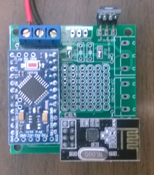
    Description: 50mm x 50mm board to hold a Arduino Mini Pro and the radio

    ###My sensorboard MYS 1..1
    Schematic: Yes
    Build Files: Yes
    Able to Modify: No
    Description: 50mm x 50mm boards with arduino pro mini and radio

    ###Schematic to MySensor Board
    Schematic: Yes
    Build Files: No
    Able to Modify: No
    Description: Schematic for a board using atmega 328 and the nrf24 radio.

    ###nRFIoT - Easy IoT Sensors
    Schematic: No
    Build Files: Yes (The .brd file is available) (https://www.dropbox.com/sh/vg0re4qo1ic6q91/AADA00TXXfzyIMQ8QLQ2xTPTa)
    Able to Modify: No
    Description: A Pro Mini Shield. A PCB, size of the Pro Mini, which can be stacked. "The finished product measures in at the size of the pro mini, and about 3 times thicker. "

    ###Stockie - item centric shopping list
    Schematic: Yes
    Build Files: Yes
    Able to Modify: No
    Description: An ATTiny PCB (so may not work with MySensors) with an NRF24. "Throughout the house there are tags (1) and panels (2) that allow you to mark one item as running low with a simple push of a button."

    Misc Links related to Custom PCB

    Etching My Own Boards

    Hardware

  • Eagle files for a MeanPenguin MySensors PCB
    M meanpenugin

    Hi,

    Any feedback would be appreciated before I send it off to be produced.
    Attached are the Schematic and the Layout and will be updated as changes are made from the suggestions.

    Using various entries in the Forum and using this as a starting point (thanks @THERICK), this is what I have...
    http://forum.mysensors.org/topic/205/my-ideal-sensor-node-pcb/22

    ##Size##
    5cm x 5cm

    ##Power##
    If using 5V Regulated

    • Use 5V Arduino Pro Mini
    • Connect pins 1 and 2 on Jumper 1
    • Connect pins 1 and 2 on Jumper 2
    • VCC is 5V
    • Install AMS1117
    • +3V3 is 3.3 volts

    If using 3.3V Regulated

    • Use 3V3 Arduino Pro Mini
    • Connect pins 2 and 3 on Jumper 1
    • Connect pins 2 and 3 on Jumper 2
    • VCC is 3.3V
    • Install a jumper wire across IN and OUT pins labeled for the AMS1117 (Don't install the AMS1117)
    • +3V3 is 3.3 volts
    • No 5v sensors

    Using Unregulated > 5V

    • Use 5V Arduino Pro Mini
    • Connect pins 1 and 2 on Jumper 1
    • Connect pins 1 and 2 on Jumper 2
    • Install the LM7805 (Vin pin on left, Vout pin on right)
    • Use capacitors (C3, C4) as needed
    • VCC is 5 volts
    • Install AMS1117
    • +3V3 is 3.3 volts

    ##Data Pins##
    Right edge of the board

    • Two digital pins on 3v3 with optional pull-up resistor.
    • One digital pins on VCC with optional pull-up resistor.

    Center of the board Mini Proto area (Columns from Left to Right)

    • VCC
    • Data pins (A0, A2, A2, D3, D5, D8)
    • Independent holes 3 x 7
    • GND

    ##Required Bill or Materials##
    1 x Arduino Pro Mini (5V or 3V3 depending on the supply power and sensor requirements)
    1 x NRF24L01+ 2.4GHz Wireless Transceiver
    1 x Capacitor for the Radio across 3V3 and Gnd
    1 x AMS1117 5V-3.3V Step Down Module (If NOT supplying 3v3 regulated power)

    ##Optional##
    1 x 7805 + Capacitors if not providing regulated power
    PCB Mount 3 Pin Plug-in Screw Terminal Block for Power In and Data pins on the Right side of the board
    Female pin headers for the Arduino and the Radio
    Sensors
    Pull-up resistors

    Panelized Gerber file sent to ITead: ArduinoMiniProBoard v2-Panel-Gerber 2014-11-04.zip [Order the 5cmx10cm board for $15, which gives you 10 boards you cut in half to make 20] (http://imall.iteadstudio.com/open-pcb/pcb-prototyping/im120418002.html).
    Note: I was able to email them and ask to double the 5cmx10cm to the 10cmx10cm for $19 netting 40 boards. You would have to do more cutting. I was able to do it easily with a box cutter and a straight edge ruler.

    Eagle Files: ArduinoMiniProBoard-v2-0.zip

    Schematic v2.GIF Board v2.GIF
    mysensors-board.PNG

    11/24/2014: Tested v2 board and it is working. I have about 50 feet with 3 walls in between with not much failures. I need to see if caps will extend the range...
    11/12/2014: Uploaded v2 Schematics and picture of the Board. Will post the Gerber files when I receive my board and they test OK.
    10/31/2014: Found problems with the board.. Need to make a Rev 2 and retest.

    Hardware

  • Eagle files for a MeanPenguin MySensors PCB
    M meanpenugin

    The board tested good.

    I have some small changes I would make for the next version but this board is good enough to start building...

    The files are attached in the first post.
    You you make enhancements, please share your enhancements so everyone else can benefit.

    Thanks
    Edward

    Hardware
  • Login

  • Don't have an account? Register

  • Login or register to search.
  • First post
    Last post
0
  • MySensors
  • OpenHardware.io
  • Categories
  • Recent
  • Tags
  • Popular