@NeverDie @mfalkvidd
Today I've resoldered the ESP8266 Chip.
Everything works perfect.
Thanks for your help!
numanx
@numanx
Posts
-
[SOLVED] Problems with ESP8266 and NRF24L01+ -
[SOLVED] Problems with ESP8266 and NRF24L01+@mfalkvidd
It seems that ESP8266 doesn't support SOFTSPIIn file included from /home/numanx/Arduino/ESP8266OTA/ESP8266OTA.ino:120:0: /home/andreihering/Arduino/libraries/MySensors/MySensors.h:248:2: error: #error Soft SPI is not available on ESP8266 -
[SOLVED] Problems with ESP8266 and NRF24L01+Finally got it!
It seems that I have a problem with the ESP8266.
After about 24 Hours of debugging I found the problem...Steps:
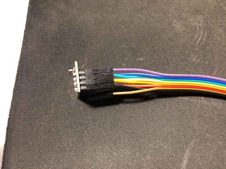
Checked if the wiring is good with a multimeter probe on each pin of the adapter(which I know it worked) and each pin of the radio to verify the correct pinout.
It seems that the pinout was ok and the wiring was also ok.
Write a sketch with all the ports from D2 to D8 in output HIGH and with a little buzzer I've tested each pin.
It seems that D7 doesn't give voltage.
Checked the pinout diagram for the ESP-12E. Checked for continuity between GPIO13(from the chip) and D7 and there was no continuity.
Tried to connect the radio MOSI Pin directly to GPIO13 and IT WORKED!0;255;3;0;9;TSM:INIT 0;255;3;0;9;TSM:INIT:TSP OK 0;255;3;0;9;TSM:INIT:GW MODE 0;255;3;0;9;TSM:READY:ID=0,PAR=0,DIS=0 0;255;3;0;9;MCO:REG:NOT NEEDEDIs there any way to move the MOSI pin from the board to another digital pin from ESP8266?
Thanks! -
[SOLVED] Problems with ESP8266 and NRF24L01+ -
[SOLVED] Problems with ESP8266 and NRF24L01+ -
[SOLVED] Problems with ESP8266 and NRF24L01+Ok, I've solved the problem with the Wireless SSID and password by uploading the HelloServer sketch from the ESP8266 examples.
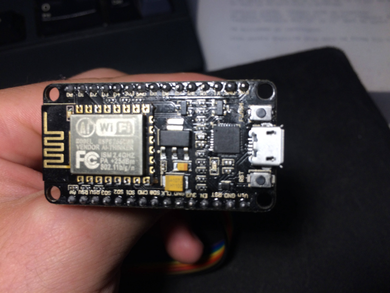
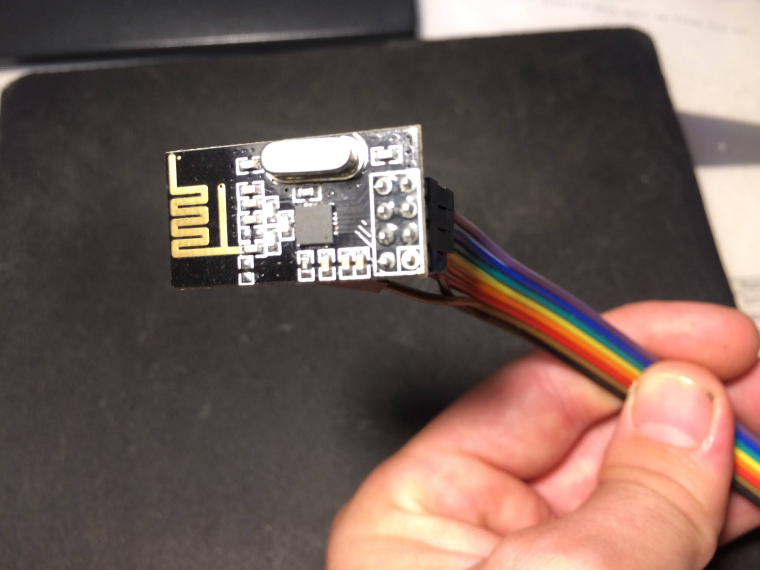
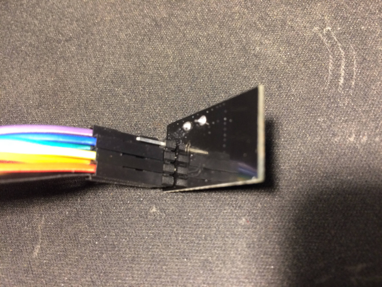
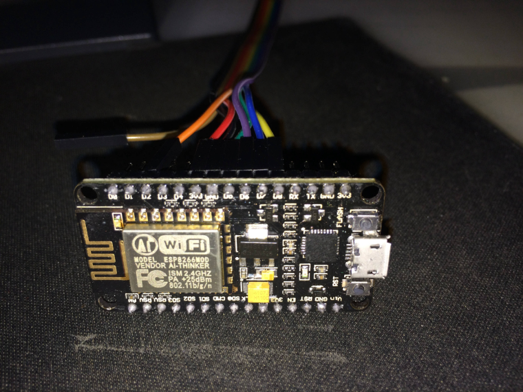
Now I rewire the ESP8266 and Radio and I will post some photos. -
[SOLVED] Problems with ESP8266 and NRF24L01+Now I have another problem...
I've tried to change the Wireless SSID and Password in the sketch and it seems that after uploading on the ESP8266 it doesn't update them. I've tried clearing EEPROM memory and now the ESP8266 seems to be stucked in the AP mode and I have some strange characters when I open Serial Monitor...0;255;3;0;9;MCO:BGN:INIT GW,CP=RNNGE--,VER=2.1.1 0;255;3;0;9;TSF:LRT:OK 0;255;3;0;9;TSM:INIT 0;255;3;0;9;TSF:WUR:MS=0 0;255;3;0;9;!TSM:INIT:TSP FAIL 0;255;3;0;9;TSM:FAIL:CNT=1 0;255;3;0;9;TSM:FAIL:PDT chg_A2:-40 -
[SOLVED] Problems with ESP8266 and NRF24L01+@NeverDie
The board selected is NodeMCU 1.0 (ESP-12E module)
I've tried suplying the adapter with 3.3v and also with 5V.@mfalkvidd
Now the radio is connected directly to the ESP8266 but still I have the same error. -
[SOLVED] Problems with ESP8266 and NRF24L01+@sundberg84 @NeverDie
Thanks for your answers.
I've connected the ESP8266 and NRF24L01+ exactly as described in Connecting the Radio(https://www.mysensors.org/build/connect_radio) at the NRF24L01+ & ESP8266 section.
Still the same error, I've tried rewiring a couple of times using different wires. -
[SOLVED] Problems with ESP8266 and NRF24L01+@sundberg84
The ESP8266 was running from my PC using a usb cable.
I've tried to power the NRF24L01+ from the ESP8266 directly with dupont cable also I've tried through the Socket adapter plate board. I've tried to power the NRF24L01+ from a 5V power supply. The NRF24L01+ ground was common with the ESP8266 ground and the VCC on the adapter(which pass through the 5V to 3.3V regulator and then to NRF24L01+) was connected from the 5V power supply.I am using the NodeMCU as described in the following link https://www.mysensors.org/build/connect_radio#nrf24l01+-&-esp8266
-
[SOLVED] Problems with ESP8266 and NRF24L01+This is the sketch that I'm using.
// Enable debug prints to serial monitor #define MY_DEBUG // Use a bit lower baudrate for serial prints on ESP8266 than default in MyConfig.h #define MY_BAUD_RATE 9600 // Enables and select radio type (if attached) #define MY_RADIO_NRF24 #define MY_GATEWAY_ESP8266 #define MY_ESP8266_SSID "MySSID" #define MY_ESP8266_PASSWORD "MyVerySecretPassword" // If using static ip you need to define Gateway and Subnet address as well #define MY_IP_GATEWAY_ADDRESS 192,168,178,1 #define MY_IP_SUBNET_ADDRESS 255,255,255,0 // The port to keep open on node server mode #define MY_PORT 5003 // How many clients should be able to connect to this gateway (default 1) #define MY_GATEWAY_MAX_CLIENTS 2 #if defined(MY_USE_UDP) #include <WiFiUdp.h> #endif #include <ESP8266WiFi.h> #include <MySensors.h> void setup() { } void presentation() { // Present locally attached sensors here } void loop() { // Send locally attached sensors data here }``` -
[SOLVED] Problems with ESP8266 and NRF24L01+Hello,
I have a problem using an ESP8266 and a NRF24L01+ module.
I followed all the steps from this guide https://forum.mysensors.org/topic/666/debug-faq-and-how-ask-for-help and still it won't work.
I am using an adapter like this https://www.aliexpress.com/item/5pcs-Socket-Adapter-Module-Board-for-NRF24L01-Wireless-Module/32368381876.html for converting the power and for power stability.
I have two NRF24L01+ modules and I've tested them with an Arduino Nano which it works.
I can't get it to work with ESP8266, I've checked the wirings multiple times.
Arduino IDE 1.6.8 with latest version of MySensors Library on Linux and Mac OS X using an ESP8266 and NRF24L01+
I've tried to power the module directly from ESP8266 and separately from a 5V PSU with the 5V regulator adapter and common ground with the ESP8266.Thanks for your help!
This is the serial monitor error:
0;255;3;0;9;TSM:INIT 0;255;3;0;9;!TSM:INIT:TSP FAIL 0;255;3;0;9;TSM:FAIL:CNT=7 0;255;3;0;9;TSM:FAIL:PDT 0;255;3;0;9;TSM:FAIL:RE-INIT``` -
Multiple ServosFound this on arduino.cc forum.
I think there should be a way for creating different servo objects for each servo but I don't know how to do that.Any sugestion from @mfalkvidd ?
#include <Servo.h> Servo myservo[6]; int pinAttch = 0; // variable to store pin attachment int servWrite = 0; // variable to store servo writing void setup() { Serial.begin(9600); for(pinAttch = 2; pinAttch < 7; pinAttch++) { myservo[pinAttch].attach(pinAttch); } } void loop() { for(servWrite = 2; servWrite < 7; servWrite++) { myservo[servWrite].write(80); delay(2000); } exit(0); }``` -
Multiple Servos@gohan
Debug print when changing the dimmer slider to different values.0;255;3;0;9;Eth: 0;0;3;0;2;
0;255;3;0;9;Eth: 0;0;3;0;2;Get Version
0;255;3;0;9;Eth: 0;1;1;1;3;7
Servo changed. new state: 7
0;255;3;0;9;Eth: 0;0;3;0;18;PING
0;255;3;0;9;Eth: 0;1;1;1;3;21
Servo changed. new state: 21
0;255;3;0;9;Eth: 0;1;1;1;3;36
Servo changed. new state: 36
0;255;3;0;9;Eth: 0;0;3;0;18;PING
0;255;3;0;9;Eth: 0;0;3;0;18;PING -
Multiple ServosOk so here is the sketch with the for cycles.
But it still won't work. The servos are presented to the Controller but it won't make any move.
I think the problem is with the void receive.
I don't know how to changedigitalWrite(message.sensor-1+RELAY_1, message.getBool()?RELAY_ON:RELAY_OFF);for the servo
myservo.write(SERVO_MAX + (SERVO_MIN-SERVO_MAX)/100 * 1.8 * val); // sets the servo position 0-180// Debug #define MY_DEBUG // Partea cu Conexiunea la net #define MY_GATEWAY_ENC28J60 #define MY_IP_ADDRESS 192,168,1,66 #define MY_PORT 5003 #define MY_MAC_ADDRESS 0xDE, 0xAD, 0xBE, 0xEF, 0xFE, 0xED #include <UIPEthernet.h> // Sfarsit parte #include <SPI.h> #include <MySensors.h> #include <Servo.h> #define SERVO_1 4 // Arduino Digital I/O pin number for first servo (second on pin+1 etc) #define NUMBER_OF_SERVOS 2 // Total number of attached servos #define SERVO_MIN 0 // Fine tune your servos min. 0-180 #define SERVO_MAX 180 // Fine tune your servos max. 0-180 #define DETACH_DELAY 900 // Tune this to let your movement finish before detaching the servo //#define CHILD_ID 10 // Id of the sensor child //MyMessage msg(CHILD_ID, V_DIMMER); Servo myservo; // create servo object to control a servo unsigned long timeOfLastChange = 0; bool attachedServo = false; bool state; void before() { for (int servo=1, pin_S=SERVO_1; servo<=NUMBER_OF_SERVOS; servo++, pin_S++) { myservo.attach(pin_S); } } void setup() { // Request last servo state at startup for (int servo=1, pin_S=SERVO_1; servo<=NUMBER_OF_SERVOS; servo++, pin_S++) { request(servo, V_DIMMER); } } void presentation() { // Send the sketch version information to the gateway and Controller sendSketchInfo("Servo", "1.0"); // Register all sensors to gw (they will be created as child devices) for (int servo=1, pin_S=SERVO_1; servo<=NUMBER_OF_SERVOS; servo++, pin_S++) { present(servo, S_DIMMER); } } void loop() { if (attachedServo && millis() - timeOfLastChange > DETACH_DELAY) { myservo.detach(); attachedServo = false; } } void receive(const MyMessage &message) { attachedServo = true; if (message.type==V_DIMMER) { // This could be M_ACK_VARIABLE or M_SET_VARIABLE int val = message.getInt(); myservo.write(SERVO_MAX + (SERVO_MIN-SERVO_MAX)/100 * 1.8 * val); // sets the servo position 0-180 // Write some debug info Serial.print("Servo changed. new state: "); Serial.println(val); } timeOfLastChange = millis(); } -
Multiple Servos -
Multiple ServosHi there,
Could someone help me with a sketch for running multiple servos.
Like in the example for the Relay Actuator
#define SERVO_1 3 // Arduino Digital I/O pin number for first relay (second on pin+1 etc)
#define NUMBER_OF_SERVOS 1 // Total number of attached relaysMy current sketch is:
// Debug
#define MY_DEBUG
// Partea cu Conexiunea la net
#define MY_GATEWAY_ENC28J60
#define MY_IP_ADDRESS 192,168,1,66
#define MY_PORT 5003
#define MY_MAC_ADDRESS 0xDE, 0xAD, 0xBE, 0xEF, 0xFE, 0xED
#include <UIPEthernet.h>
// Sfarsit parte

#include <SPI.h>
#include <MySensors.h>
#include <Servo.h>

#define SERVO_DIGITAL_OUT_PIN 4
#define SERVO_MIN 0 // Fine tune your servos min. 0-180
#define SERVO_MAX 180  // Fine tune your servos max. 0-180
#define DETACH_DELAY 900 // Tune this to let your movement finish before detaching the servo
#define CHILD_ID 10   // Id of the sensor child

MyMessage msg(CHILD_ID, V_DIMMER);
Servo myservo;  // create servo object to control a servo
                // a maximum of eight servo objects can be created Sensor gw(9,10);
unsigned long timeOfLastChange = 0;
bool attachedServo = false;
bool state;

void setup()
{
  // Request last servo state at startup
  request(CHILD_ID, V_DIMMER);
}

void presentation()  {
  // Send the sketch version information to the gateway and Controller
  sendSketchInfo("Servo", "1.0");

  // Register all sensors to gw (they will be created as child devices)
  present(CHILD_ID, S_DIMMER);
}

void loop()
{
  if (attachedServo && millis() - timeOfLastChange > DETACH_DELAY) {
     myservo.detach();
     attachedServo = false;
  }
}

void receive(const MyMessage &message) {
  myservo.attach(SERVO_DIGITAL_OUT_PIN);
  attachedServo = true;
  if (message.type==V_DIMMER) { // This could be M_ACK_VARIABLE or M_SET_VARIABLE
     int val = message.getInt();
     myservo.write(SERVO_MAX + (SERVO_MIN-SERVO_MAX)/100 * 1.8 * val); // sets the servo position 0-180
     // Write some debug info
     Serial.print("Servo changed. new state: ");
     Serial.println(val);
     }
   timeOfLastChange = millis();
}
Thanks!
-
UPS Monitoring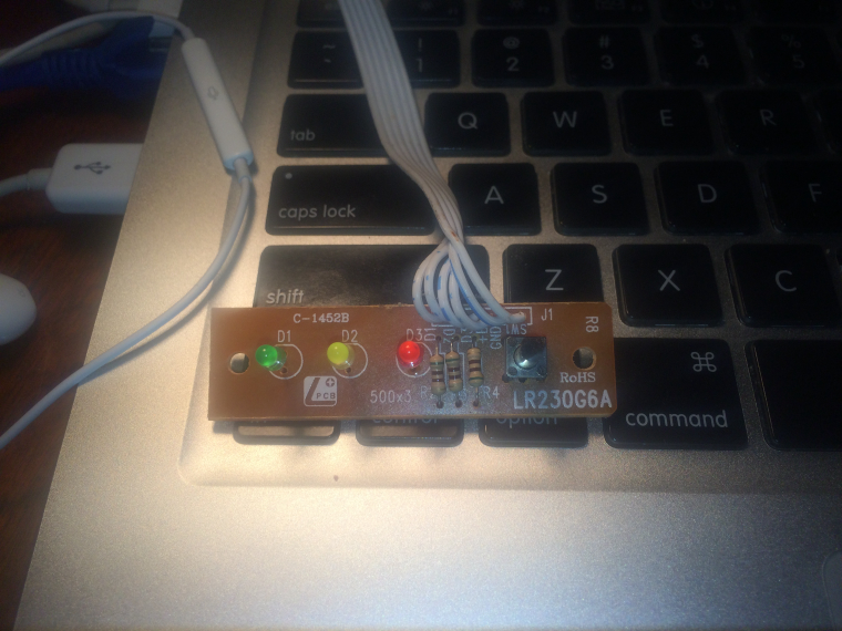 Hello,
I have an UPS Vmark 650MK and I want to monitor it through Arduino and Domoticz.Can somebody help me with the code for reading the values from the panel?
I have 3 LED's, Normal State, Backup and Fault.
I want to read the values from those 3 LED's with HIGH and LOW / 1 and 0 in domoticz.Here is the schematic for the front panel.
-
Multiple Sensors on Gateway@gohan I understand what you are saying but if I am doing in that way I will spam the controller with the interrupts(flaps) right now it works like this
if pin=0 send the state of the pin(the next update is when pin state changes), if pin=1 send the state and wait for 10 seconds for the next update.For the moment I have found a solution with millis[if(time%frequency==0)]:
time=millis()/1000;
if(time%10 ==0)
Any suggestion for improving this part?
-
Multiple Sensors on GatewayThank you for your reply!
The motion sensor part from the sketch works perfectly, the problem is with the temperature part.If I am using wait or sleep for temperature, arduino won't listen the motion sensor until the time elapses.
If I am commenting the wait the sensor will spam the controller until the controller stop receiving data from arduino.