[SOLVED] Problems with ESP8266 and NRF24L01+
-
It's hard to tell from your photos what is wired to what.
Suggest you upgrade to the current Arduino IDE and verify that you have the most current NodeMCU board definition installed. Also confirm that you're using the latest release of the Mysensors library.
Have you verified that your hardware is working? e.g. try the radio module in a different "known good" platform and see if it runs correctly. On the NodeMCU, try driving something else that has a SPI interface and confirm that it works properly.
If all of the above checks out, then I would think the next step would be to use a logic probe to see if you're getting the proper signals sent between your NodeMCU and the nRF24L01 module. If not, maybe you need to add a pull-up or a pull-down resistor on one of the datalines. The logic probe would tell the tale.
-
Finally got it!
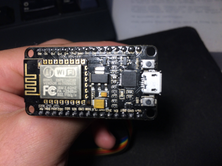
It seems that I have a problem with the ESP8266.
After about 24 Hours of debugging I found the problem...Steps:
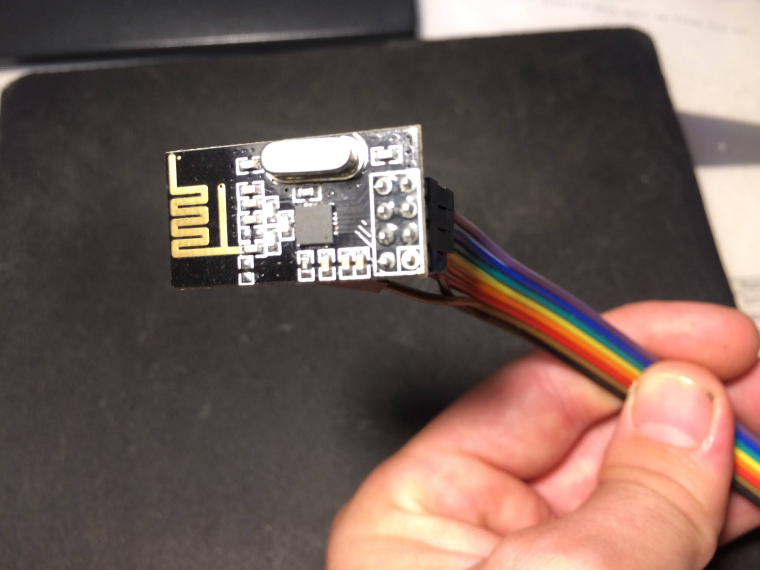
Checked if the wiring is good with a multimeter probe on each pin of the adapter(which I know it worked) and each pin of the radio to verify the correct pinout.
It seems that the pinout was ok and the wiring was also ok.
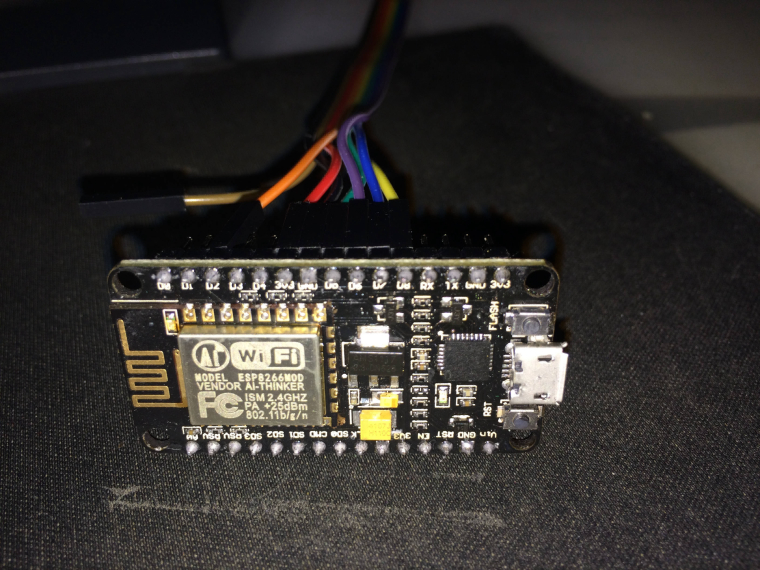
Write a sketch with all the ports from D2 to D8 in output HIGH and with a little buzzer I've tested each pin.
It seems that D7 doesn't give voltage.
Checked the pinout diagram for the ESP-12E. Checked for continuity between GPIO13(from the chip) and D7 and there was no continuity.
Tried to connect the radio MOSI Pin directly to GPIO13 and IT WORKED!0;255;3;0;9;TSM:INIT 0;255;3;0;9;TSM:INIT:TSP OK 0;255;3;0;9;TSM:INIT:GW MODE 0;255;3;0;9;TSM:READY:ID=0,PAR=0,DIS=0 0;255;3;0;9;MCO:REG:NOT NEEDEDIs there any way to move the MOSI pin from the board to another digital pin from ESP8266?
Thanks! -
Finally got it!
It seems that I have a problem with the ESP8266.
After about 24 Hours of debugging I found the problem...Steps:
Checked if the wiring is good with a multimeter probe on each pin of the adapter(which I know it worked) and each pin of the radio to verify the correct pinout.
It seems that the pinout was ok and the wiring was also ok.
Write a sketch with all the ports from D2 to D8 in output HIGH and with a little buzzer I've tested each pin.
It seems that D7 doesn't give voltage.
Checked the pinout diagram for the ESP-12E. Checked for continuity between GPIO13(from the chip) and D7 and there was no continuity.
Tried to connect the radio MOSI Pin directly to GPIO13 and IT WORKED!0;255;3;0;9;TSM:INIT 0;255;3;0;9;TSM:INIT:TSP OK 0;255;3;0;9;TSM:INIT:GW MODE 0;255;3;0;9;TSM:READY:ID=0,PAR=0,DIS=0 0;255;3;0;9;MCO:REG:NOT NEEDEDIs there any way to move the MOSI pin from the board to another digital pin from ESP8266?
Thanks!Great work @numanx !
It is possible to use software spi instead of hardware spi (hardware spi only works with the default pins). See https://www.mysensors.org/build/ethernet_gateway for how to enable software spi and use #define directives to use different pins.
-
Finally got it!
It seems that I have a problem with the ESP8266.
After about 24 Hours of debugging I found the problem...Steps:
Checked if the wiring is good with a multimeter probe on each pin of the adapter(which I know it worked) and each pin of the radio to verify the correct pinout.
It seems that the pinout was ok and the wiring was also ok.
Write a sketch with all the ports from D2 to D8 in output HIGH and with a little buzzer I've tested each pin.
It seems that D7 doesn't give voltage.
Checked the pinout diagram for the ESP-12E. Checked for continuity between GPIO13(from the chip) and D7 and there was no continuity.
Tried to connect the radio MOSI Pin directly to GPIO13 and IT WORKED!0;255;3;0;9;TSM:INIT 0;255;3;0;9;TSM:INIT:TSP OK 0;255;3;0;9;TSM:INIT:GW MODE 0;255;3;0;9;TSM:READY:ID=0,PAR=0,DIS=0 0;255;3;0;9;MCO:REG:NOT NEEDEDIs there any way to move the MOSI pin from the board to another digital pin from ESP8266?
Thanks!@numanx said in Problems with ESP8266 and NRF24L01+:
Checked the pinout diagram for the ESP-12E. Checked for continuity between GPIO13(from the chip) and D7 and there was no continuity.
Tried to connect the radio MOSI Pin directly to GPIO13 and IT WORKED!Good work!
Check the solder connection between the GPIO13 and the pcb. Probably it's faulty. With a little luck probably you can just re-solder the connection manually, and `then you'll be good to go.
-
Great work @numanx !
It is possible to use software spi instead of hardware spi (hardware spi only works with the default pins). See https://www.mysensors.org/build/ethernet_gateway for how to enable software spi and use #define directives to use different pins.
@mfalkvidd
It seems that ESP8266 doesn't support SOFTSPIIn file included from /home/numanx/Arduino/ESP8266OTA/ESP8266OTA.ino:120:0: /home/andreihering/Arduino/libraries/MySensors/MySensors.h:248:2: error: #error Soft SPI is not available on ESP8266 -
@mfalkvidd
It seems that ESP8266 doesn't support SOFTSPIIn file included from /home/numanx/Arduino/ESP8266OTA/ESP8266OTA.ino:120:0: /home/andreihering/Arduino/libraries/MySensors/MySensors.h:248:2: error: #error Soft SPI is not available on ESP8266 -
@numanx said in Problems with ESP8266 and NRF24L01+:
Checked the pinout diagram for the ESP-12E. Checked for continuity between GPIO13(from the chip) and D7 and there was no continuity.
Tried to connect the radio MOSI Pin directly to GPIO13 and IT WORKED!Good work!
Check the solder connection between the GPIO13 and the pcb. Probably it's faulty. With a little luck probably you can just re-solder the connection manually, and `then you'll be good to go.
-
This thread has been a life saver for me.
Just wanted to drop a line for anyone else who might be despairing why despite numerous tests, the radio would still not work on the NodeMCU.In my case, it was NodeMCU v3 from Lolin and I had two traces not workingbetween GPIO13 and GPIO12 - there was no continuity of the trace between the ESP-12E chip and the board pins. I had to solder those two traces together and now - everything works!
Thank you for inspiring me to look for this problem.

Hello! It looks like you're interested in this conversation, but you don't have an account yet.
Getting fed up of having to scroll through the same posts each visit? When you register for an account, you'll always come back to exactly where you were before, and choose to be notified of new replies (either via email, or push notification). You'll also be able to save bookmarks and upvote posts to show your appreciation to other community members.
With your input, this post could be even better 💗
Register Login