I recently decided to see if I could automate my oven so I could turn it on/off and set the temperature remotely. The oven is electric and has a massive plug going into the wall (I think it's a 30A, 220V but I never checked). I figured the only way I would be comfortable doing this was to "press" the momentary push buttons in the existing circuitry. I did not want to add existing relays or anything of that nature. I thought it would be easy figure out how to "press" existing buttons with an Arduino but it was surprisingly difficult (for me at least) to find any info on the subject. So, I decided to make a how to video in case anyone else wants to attempt a similar project.
The video is more generic and covers how to simulate a button press with an Arduino instead of a step by step guide on how to automate an oven. It's not specifically related to MySensors but hopefully it will be useful to someone out there who was like me looking to automate a device with pre-existing buttons.
Video
https://youtu.be/6bSFkKDxA18
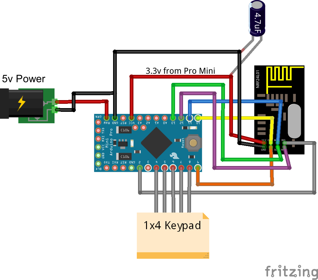
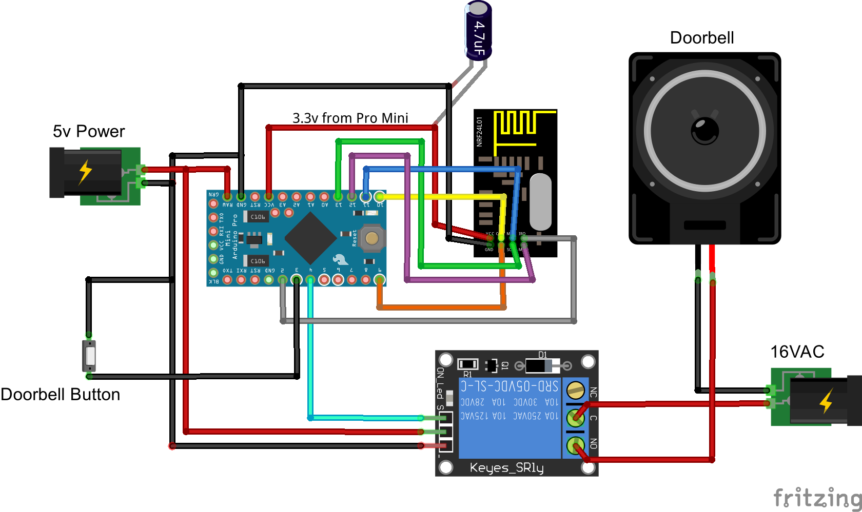
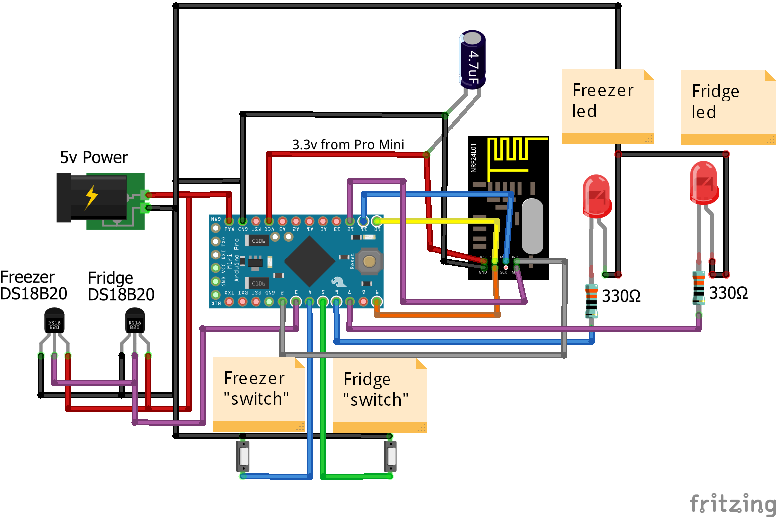
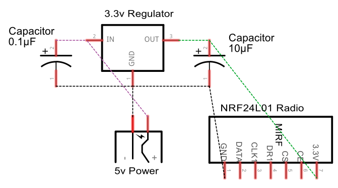
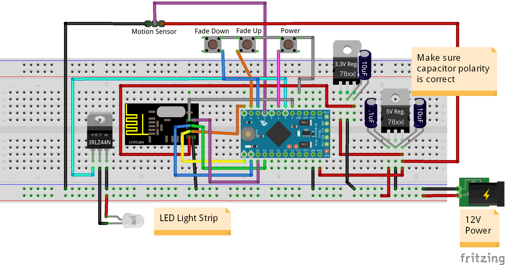
Wiring
Here is a wiring diagram for each type of switch: ground side and voltage side.
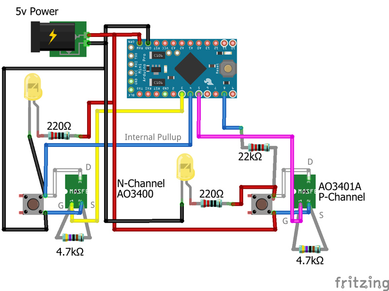
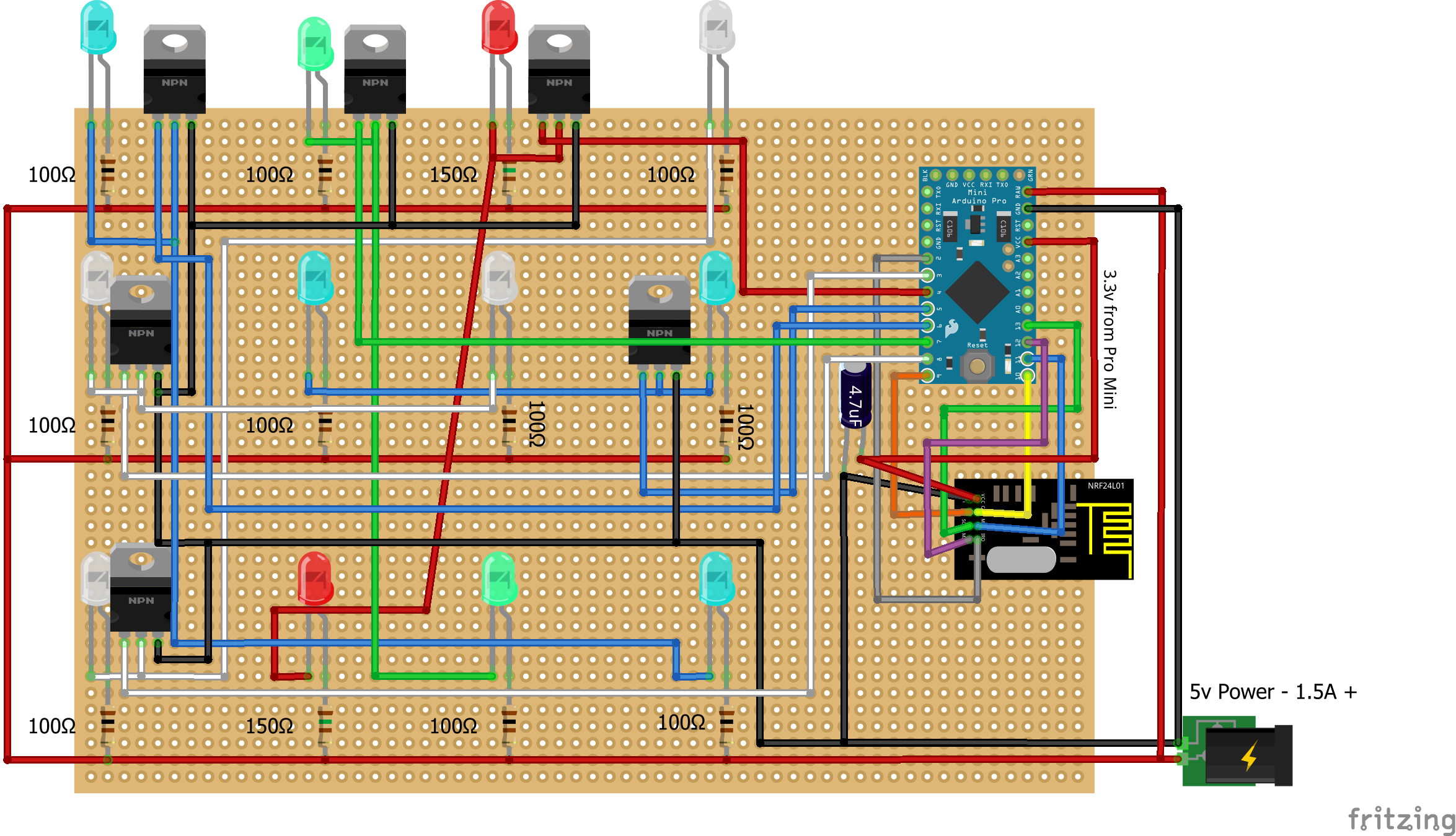
MOSFETs
I used the Alpha & Omega AO3401A (P-Channel) and AO3400 (N-Channel) MOSFETs for this project. They are very cheap. I got 100pcs of each type for around $3 total. Here is an example of where they can be found (but you may want to do some searching for the best price):
https://www.aliexpress.com/item/Free-shipping-20pcs-SMD-mosfet-transistor-SOT-23-AO3401/32359403044.html?spm=a2g0s.9042311.0.0.ej97EO
https://www.aliexpress.com/item/Free-shipping-20pcs-SMD-mosfet-transistor-SOT-23-AO3400/32360580221.html?spm=a2g0s.9042311.0.0.ej97EO
Basic Demo Code
#include <Bounce2.h>

#define GND_GATE_PIN 3
#define VCC_GATE_PIN 5
#define GND_DETECT_PIN 4
#define VCC_DETECT_PIN 8

#define BUTTON_PRESS_DELAY 100 //The amount of delay used for a button press

//Track button presses
uint8_t gndValuePrev = 1;
uint8_t vccValuePrev = 0;

//LED button on/off tracking
uint8_t gndLedOn = 0;
uint8_t vccLedOn = 0;

unsigned long gndMillis;
unsigned long vccMillis;

// Instantiate a Bounce object
Bounce gndDebouncer = Bounce();
Bounce vccDebouncer = Bounce();


void setup() {
  Serial.begin(115200);

  //Setup the pins
  pinMode(GND_GATE_PIN, OUTPUT);
  pinMode(VCC_GATE_PIN, OUTPUT);
  pinMode(GND_DETECT_PIN, INPUT_PULLUP);
  pinMode(VCC_DETECT_PIN, INPUT);

  //Start with all outputs (buttons) not enabled (pressed)
  digitalWrite(GND_GATE_PIN, 0);
  digitalWrite(VCC_GATE_PIN, 1);

  // After setting up the buttons, setup debouncers
  gndDebouncer.attach(GND_DETECT_PIN);
  gndDebouncer.interval(50);
  vccDebouncer.attach(VCC_DETECT_PIN);
  vccDebouncer.interval(50);

}

void loop() {
  unsigned long currentMillis = millis(); //Get the current millis (used for timers)

  // Update the debouncers
  gndDebouncer.update();
  vccDebouncer.update();

  // Get the update value
  uint8_t gndValue = gndDebouncer.read();
  uint8_t vccValue = vccDebouncer.read();

  if (gndValue != gndValuePrev)
  {
    if (gndValue == 0)
    {
      Serial.println(F("Ground Button Pressed"));
      if (gndLedOn == 0)
      {
        //Don't echo the button push if it was turned on by the Arduino
        gndMillis = currentMillis + 1000;
        gndLedOn = 1;
      }
    }
    gndValuePrev = gndValue;
  }
  if (vccValue != vccValuePrev)
  {
    if (vccValue == 1)
    {
      Serial.println(F("VCC Button Pressed"));
      if (vccLedOn == 0)
      {
        //Don't echo the button push if it was turned on by the Arduino
        vccMillis = currentMillis + 1000;
        vccLedOn = 1;
      }

    }
    vccValuePrev = vccValue;
  }

  //Turn on led 1 second after button pressed
  if (gndLedOn == 1 && currentMillis > gndMillis)
  {
    nChannelPress(GND_GATE_PIN);
    gndLedOn = 0;
  }

  if (vccLedOn == 1 && currentMillis > vccMillis)
  {
    pChannelPress(VCC_GATE_PIN);
    vccLedOn = 0;
  }

}

void pChannelPress(uint8_t buttonPinName)
{
  //Simulate a button press
  digitalWrite(buttonPinName, 0); //Ground to enable
  delay(BUTTON_PRESS_DELAY);
  digitalWrite(buttonPinName, 1); //VCC to disable
  delay(BUTTON_PRESS_DELAY);
}

void nChannelPress(uint8_t buttonPinName)
{
  //Simulate a button press
  digitalWrite(buttonPinName, 1); //VCC to disable
  delay(BUTTON_PRESS_DELAY);
  digitalWrite(buttonPinName, 0); //Ground to enable
  delay(BUTTON_PRESS_DELAY);
}
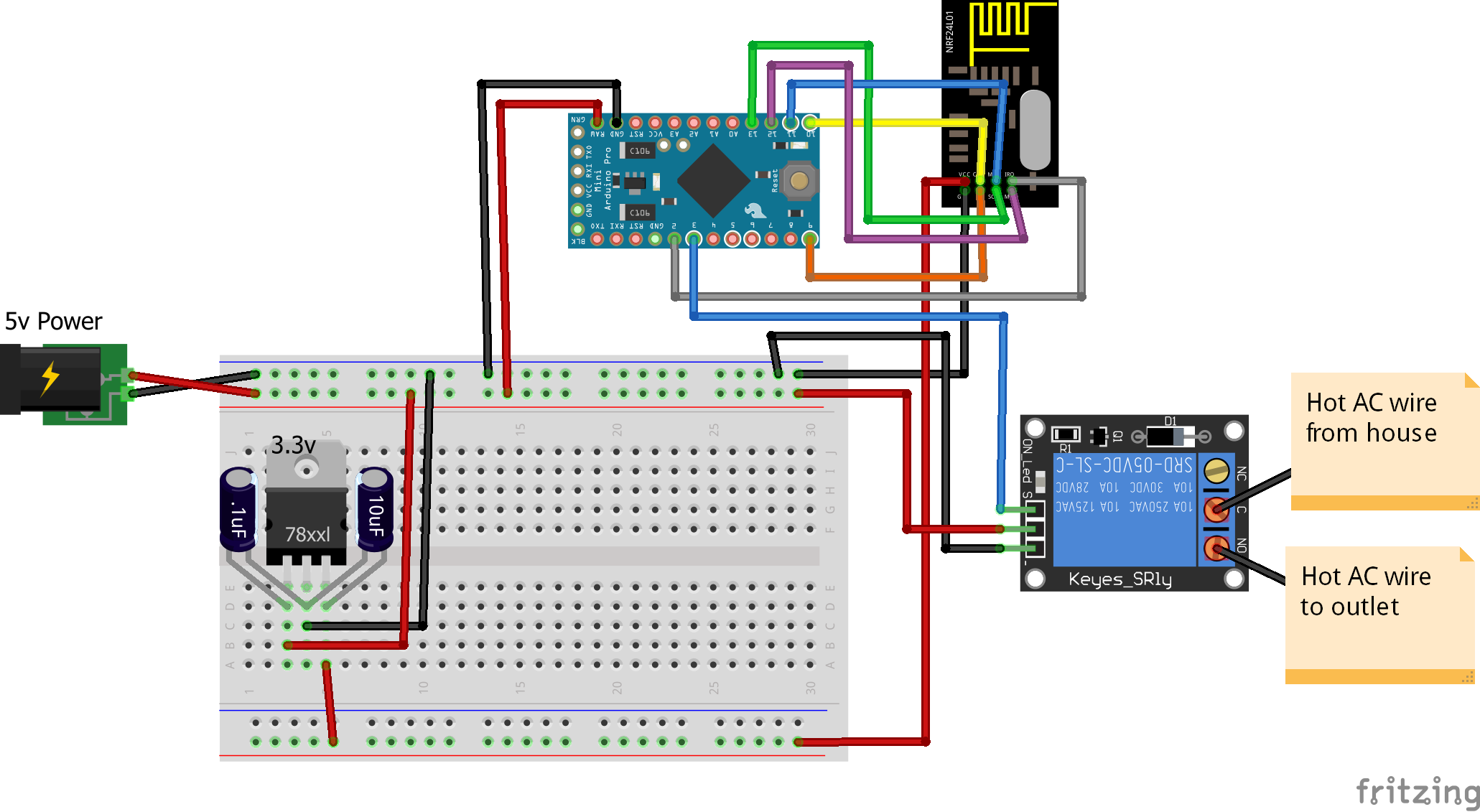
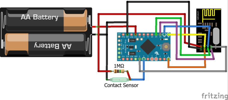
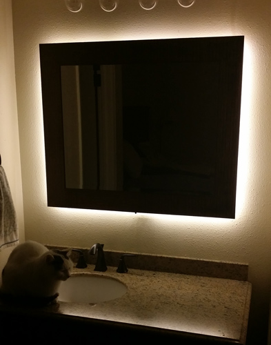
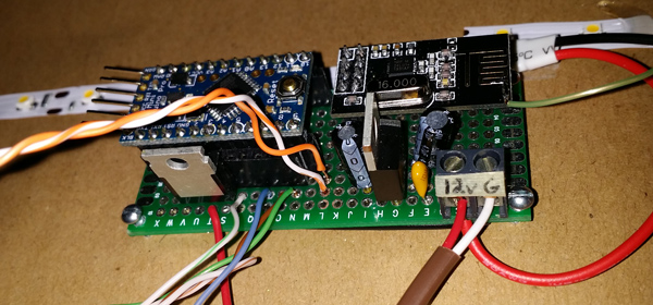
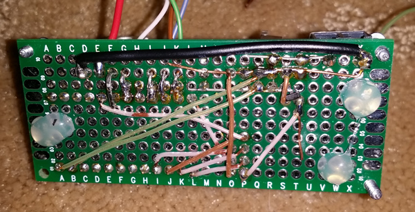
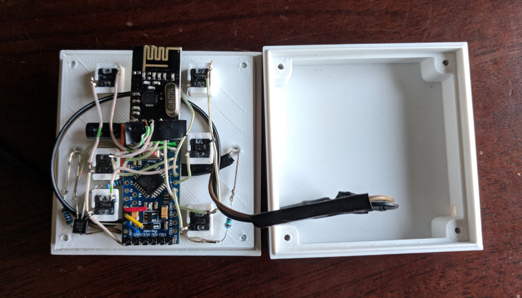
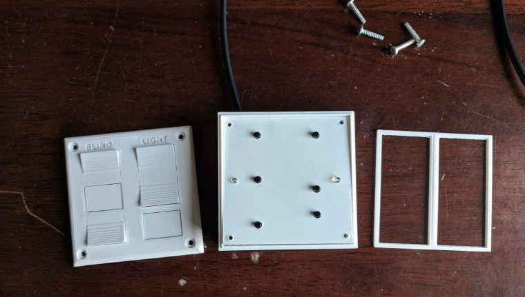
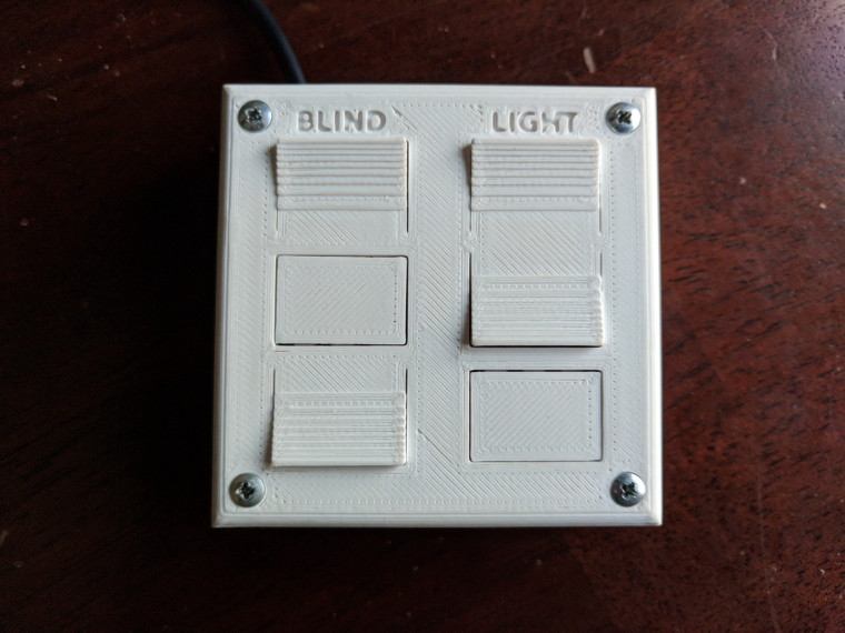
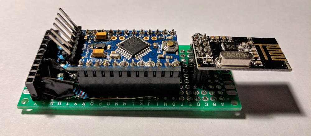
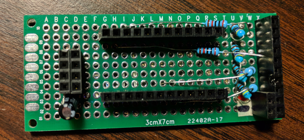
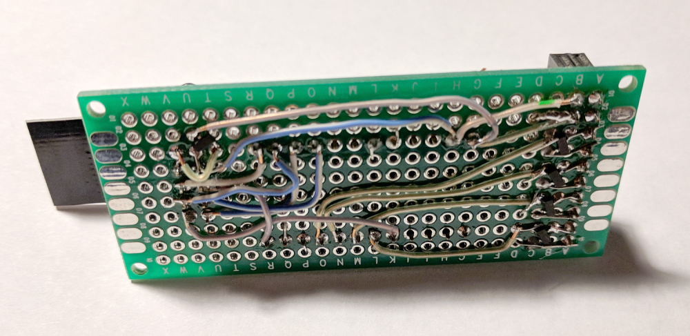
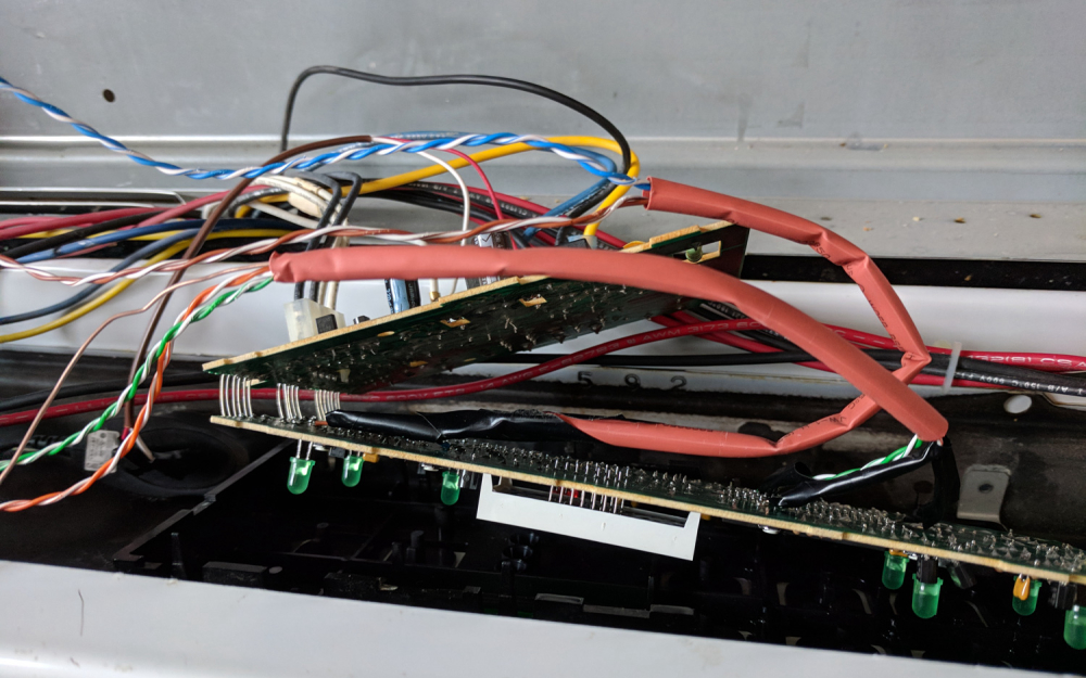
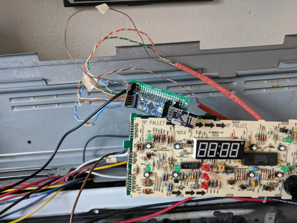
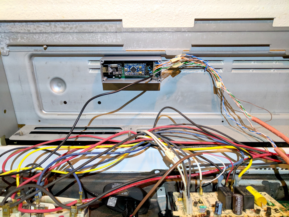
In case you're interested, here is the code for my oven project as well as some pictures.
Oven Code
/*
This will control physical buttons on a device. In my case, an oven. It will also read
button presses and send the status back to the controller. I used 4.7k resistors on the
P-Channel MOSFET gate pins to hold them high (off) in case there are issues with the
Arduino. These can be omitted if you don't care if your switch floats (which you probably
do). I used larger resistors (somewhere around 20-30k) to detect a button press.
These are connected to the drain side of the button/MOSFET
Uses the bounce2 library to debounce the buttons
*/
#define SKETCH_NAME "Oven Control"
#define SKETCH_VERSION "1.0"
// Enable debug prints to serial monitor
//#define MY_DEBUG //MySensors debug messages
//#define LOCAL_DEBUG //Code specific debug messages
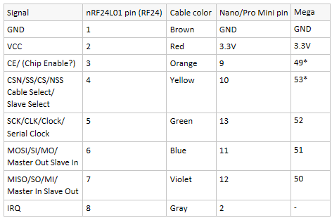
// Enable and select radio type attached
#define MY_RADIO_NRF24
//#define MY_RADIO_RFM69
#define MY_RF24_PA_LEVEL RF24_PA_HIGH //Options: RF24_PA_MIN, RF24_PA_LOW, RF24_PA_HIGH, RF24_PA_MAX
#define MY_RF24_CHANNEL 76
//#define MY_NODE_ID 1 //Manually set the node ID here. Comment out to auto assign
#include <MySensors.h>
#include <Bounce2.h>
#ifndef BAUD_RATE
#define BAUD_RATE 115200
#endif
#ifdef LOCAL_DEBUG
#define dbg(...) Serial.print(__VA_ARGS__)
#define dbgln(...) Serial.println(__VA_ARGS__)
#else
#define dbg(x)
#define dbgln(x)
#endif
#define DWELL_TIME 50 //value used in all wait calls (in milliseconds) this allows for radio to come back to power after a transmission, ideally 0
#define CHILD_ID_OVEN 0
#define CANCEL_PIN 3
#define BAKE_PIN 4
#define UP_PIN 5
#define DOWN_PIN 6
#define OVEN_OFF_PIN 7 //GPIO Pin for detecting when the physical "off" button is pressed at the oven
#define OVEN_ON_PIN 8 //GPIO Pin for detecting when the physical "on" button is pressed at the oven
#define BUTTON_ON 0 // GPIO value to write for simulating a button press (0 for P-Channel MOSFET)
#define BUTTON_OFF 1 // GPIO value to write for simulating a button not pressed (1 for P-Channel MOSFET)
#define PRESSED 1 //The value that is received when the physical butons are pressed (1 for P-Channel MOSFET)
#define HEAT_LOW_LIMIT 170 //The lowest temp the heat can be set to
#define HEAT_HIGH_LIMIT 550 //The highest temp the heat can be set to
#define OVEN_ON_TEMP 350 //The default temp that the oven is set to when first turned on
#define DELAY_OVEN_CHANGE 5000 //The amount of time to wait for additional commands from gateway before applying previous commands (give time for user to fine tune temperature)
#define BUTTON_PRESS_DELAY 100 //The amount of delay used for a button press
#define TEMP_INCREMENT 5 //Degrees to increment with each button press
MyMessage msgHeatMode(CHILD_ID_OVEN, V_HVAC_FLOW_STATE);
MyMessage msgHeatSetpoint(CHILD_ID_OVEN, V_HVAC_SETPOINT_HEAT);
uint16_t heatSetPoint = HEAT_LOW_LIMIT; //The current oven heat set point. Default is HEAT_LOW_LIMIT if no value is received from gateway.
//uint16_t heatSetPointPrev = HEAT_LOW_LIMIT; //The previous oven heat set point. Default is HEAT_LOW_LIMIT if no value is received from gateway.
uint8_t ovenStatus = 0; //The current status of the oven 1 = on, 0 = off
uint8_t ovenStatusPrev = 0; //The previous status of the oven 1 = on, 0 = off
uint8_t ovenStateCommand = 2; //used to track oven on/off commands from controller
uint8_t receivedCommand = 0; //Used to get config states from controller at start up
unsigned long commandDelayMillis; //Used to track delay time before the received commands are applied
unsigned long sendDelayMillis; //Wait to update the controller with on/off status until the automation is done
// Instantiate a Bounce object
Bounce onDebouncer = Bounce();
Bounce offDebouncer = Bounce();
void before()
{
#ifdef LOCAL_DEBUG
Serial.begin(BAUD_RATE);
#endif
}
void presentation()
{
// Send the sketch version information to the gateway
sendSketchInfo(SKETCH_NAME, SKETCH_VERSION);
// Register all sensors to gw (they will be created as child devices)
present(CHILD_ID_OVEN, S_HEATER);
wait(DWELL_TIME);
//metric = getConfig().isMetric; //This has been removed as it will default to metric if connection to the gateway is not established (bad for imperial users)
//wait(DWELL_TIME);
}
void setup() {
//Setup the pins
pinMode(CANCEL_PIN, OUTPUT);
pinMode(BAKE_PIN, OUTPUT);
pinMode(UP_PIN, OUTPUT);
pinMode(DOWN_PIN, OUTPUT);
pinMode(OVEN_ON_PIN, INPUT);
pinMode(OVEN_OFF_PIN, INPUT);
//Start with all outputs (buttons) not enabled (pressed)
digitalWrite(CANCEL_PIN, BUTTON_OFF);
digitalWrite(BAKE_PIN, BUTTON_OFF);
digitalWrite(UP_PIN, BUTTON_OFF);
digitalWrite(DOWN_PIN, BUTTON_OFF);
// After setting up the buttons, setup debouncers
onDebouncer.attach(OVEN_ON_PIN);
onDebouncer.interval(1);
offDebouncer.attach(OVEN_OFF_PIN);
offDebouncer.interval(5);
uint8_t reqCounter = 0;
while (receivedCommand == 0)
{
dbgln("Requesting heat setpoint");
request(CHILD_ID_OVEN, V_HVAC_SETPOINT_HEAT); //Request state from gateway
wait(500);
reqCounter++;
if (reqCounter > 5)
{
dbgln("Failed to get heat setpoint!");
break;
}
}
wait(5000); //Wait for 10 seconds to give time for commands to be received (so the oven doesn't turn on when the microcontroller starts)
receivedCommand = 0;
}
void loop() {
unsigned long currentMillis = millis(); //Get the current millis (used for timers)
// Update the debouncers
onDebouncer.update();
offDebouncer.update();
// Get the update value
uint8_t onValue = onDebouncer.read();
uint8_t offValue = offDebouncer.read();
if (onValue == 1)
{
ovenStatus = 1;
sendDelayMillis = currentMillis;
dbgln(F("On Pressed"));
}
if (offValue == 1)
{
ovenStatus = 0;
sendDelayMillis = currentMillis;
dbgln(F("Off Pressed"));
}
if (ovenStatus != ovenStatusPrev && currentMillis - sendDelayMillis > 1000)
{
//Send new ovenStatus to gateway
send(msgHeatMode.set(ovenStatus == 1 ? "HeatOn" : "Off"));
dbgln(ovenStatus);
ovenStatusPrev = ovenStatus;
}
if (receivedCommand)
{
//Received a command to turn on/off the oven
if (ovenStateCommand == 0)
{
//Turn off the oven right away (no delay necessary)
buttonPress(CANCEL_PIN);
receivedCommand = 0;
ovenStateCommand = 2; //Set to some number other than 1 or 0 to allow oven to be adjusted when the heatSetPoint changed
ovenStatus = 0;
}
else
{
//We need to turn on and/or change the temp but we want to wait for all the commands to come in first (DELAY_OVEN_CHANGE time)
if (currentMillis - DELAY_OVEN_CHANGE > commandDelayMillis)
{
if (ovenStateCommand == 1 || ovenStatus == 1)
{
//The oven is either on or should be on. Since we are not keeping track of the temperature
//we need to turn the oven off then back on to ensure we get the correct temp
buttonPress(CANCEL_PIN);
//Now, turn it on and adjust the temp to the correct setting
buttonPress(BAKE_PIN);
wait(BUTTON_PRESS_DELAY * 2); //wait for the oven to turn on before adjusting temp
buttonPress(UP_PIN); //Oven starts at 0 so we need to press a button to start at OVEN_ON_TEMP
wait(BUTTON_PRESS_DELAY * 2);
uint16_t tempChange = OVEN_ON_TEMP;
if (heatSetPoint < OVEN_ON_TEMP)
{
//The temp should be adjusted lower (also rounding to nearest TEMP_INCREMENT)
while (tempChange > heatSetPoint + (TEMP_INCREMENT / 2))
{
buttonPress(DOWN_PIN);
wait(BUTTON_PRESS_DELAY);
dbg(F("Lowered temp to: "));
dbgln(tempChange);
tempChange -= TEMP_INCREMENT;
}
}
else
{
//The temp should be adjusted lower (also rounding to nearest TEMP_INCREMENT)
while (tempChange < heatSetPoint - (TEMP_INCREMENT / 2))
{
buttonPress(UP_PIN);
wait(BUTTON_PRESS_DELAY * 2);
dbg(F("Raised temp to: "));
dbgln(tempChange);
tempChange += TEMP_INCREMENT;
}
}
send(msgHeatSetpoint.set(tempChange)); //Send value to gateway
ovenStatus = 1;
}
receivedCommand = 0;
ovenStateCommand = 2; //Set to some number other than 1 or 0 to allow oven to be adjusted when the heatSetPoint changed
}
}
}
}
void receive(const MyMessage &message)
{
dbg(F("msg data: "));
dbgln(String(message.data));
if (message.isAck()) {
dbgln(F("Ack from gateway"));
}
if (message.type == V_HVAC_FLOW_STATE && !message.isAck()) {
//find the mode
if (String(message.data) == "Off")
{
ovenStateCommand = 0;
}
else if (String(message.data) == "HeatOn")
{
ovenStateCommand = 1;
}
else
{
dbgln(F("Invalid state received"));
}
dbg(F("Oven state: "));
dbgln(ovenStateCommand);
commandDelayMillis = millis();
receivedCommand = 1;
}
if (message.type == V_HVAC_SETPOINT_HEAT && !message.isAck()) {
uint16_t value = atoi(message.data);
if (value < HEAT_LOW_LIMIT)
{
heatSetPoint = HEAT_LOW_LIMIT;
}
else if (value > HEAT_HIGH_LIMIT)
{
heatSetPoint = HEAT_HIGH_LIMIT;
}
else
{
heatSetPoint = value;
}
dbg(F("Heat setpoint: "));
dbgln(heatSetPoint);
commandDelayMillis = millis();
receivedCommand = 1;
}
}
void buttonPress(uint8_t buttonPinName)
{
//Simulate a button press
digitalWrite(buttonPinName, BUTTON_ON);
wait(BUTTON_PRESS_DELAY);
digitalWrite(buttonPinName, BUTTON_OFF);
wait(BUTTON_PRESS_DELAY);
}